Combustion provides heat for many industrial processes and accounts for over 80% of the power used by turbines to generate electricity. Over the past several decades, regulatory action and concerns over environmental air pollutants, such as oxides of nitrogen (NOx), have pushed industrial process designers to develop burners that lower pollutant emissions and prompted manufacturers to switch to cleaner-burning fuels. Going forward, industrial combustion — both for process heat and power generation — will be characterized by an increasingly diverse fuel supply and a greater need to reduce pollutants and carbon dioxide emissions. As substitutes to natural gas, coal and oil, alternative fuels are being considered by the chemical process industries (CPI) for power generation and process heating. These include low-heat-content fuels such as landfill gas, biogas and synthesis gas (syngas), as well as hydrogen.
To take full advantage of these alternative fuels, CPI engineers are exploring a number of approaches aimed at reducing carbon emissions, improving fuel flexibility and increasing efficiency for combustion systems. A key part of the effort is the development of combustor designs that operate effectively using a range of fuels while maintaining low emissions and stable performance.
In this article, we discuss the low-swirl combustor design, its operation and its performance with natural gas, hydrogen and low-heat-content fuels. We believe that the low-swirl combustor design can make a substantial contribution toward a reduced carbon footprint and higher air quality.
New demands on burners
For many years, burners for industrial process heating and power generation were relatively simple devices. The primary criteria for burners were good heat distribution, good flame stability and turndown capability. Until recent decades, emissions were not a primary concern in burner development.
Industrial burner manufacturers have successfully responded to the challenge of reducing emissions from combustion systems. There are a number of lean, premixed burner designs for use with natural gas that can achieve low (sub-15 ppm or even single-digit) NOx emissions. However, concerns about CO2 emissions and fossil fuel availability, as well as discussions over the creation of a carbon cap-and-trade program or other carbon tax, have created new challenges.
Burners that have been carefully optimized to operate cleanly with natural gas may not be capable of operating with alternative fuels. The combustion properties of these alternative fuels can differ significantly from natural gas. Combustors that have been optimized for clean operation on natural gas may not burn the alternative fuels cleanly, or even worse, may become unstable and get damaged or destroyed.
The ideal burner design would be able to operate cleanly on both natural gas and alternative fuels, and be able to switch between fuels with little or no change in operating conditions.
Production of pollutants in flames depends on several factors — fuel-air mixing, fuel-air ratio, flame temperature and fuel composition. Gaseous fuels tend to burn more cleanly since they can be mixed with air to produce a uniform air-fuel mixture without undergoing a phase change. It is more difficult to produce uniform mixtures from liquid fuels. Liquid fuels are sprayed into the air for combustion, and fuel droplets are surrounded by a fuel-rich zone until the liquid fuel is completely vaporized. The processes involved with solid fuel combustion are even more complicated. All of these factors must be considered in the development of cleaner-burning combustion systems.
Stoichiometry and temperature
The temperature at which a flame burns depends on the type of fuel used and the flame stoichiometry. In combustion, stoichiometry is a term that is used to describe the ratio of fuel to oxidizer consumed during the combustion process. For example, in the combustion of methane (CH4 + 2O2 —> CO2 + 2H2O), twice as much oxygen is consumed as methane on a mole or volume basis. The equivalence ratio of a system is defined as the ratio of the experimental fuel-to-oxidizer ratio to the stoichiometric fuel-to-oxidizer ratio. The equivalence ratio may be expressed as either: phi (fuel-to-oxidizer) or lambda (air-to-fuel).
In the methane combustion reaction above, there is no residual oxygen and no residual fuel, so the system has an equivalence ratio of one both as fuel-to-oxidizer ratio or air-to-fuel ratio. The equivalence ratio phi will be used in this article when discussing fuel-air mixtures. When there is less fuel than air available for the flame (phi <1), the flame is lean and burns at a lower temperature than a flame at stoichiometric conditions. A rich flame with more fuel than available air (phi >1) also burns at a lower temperature than a stoichiometric flame, but generates partially oxidized species from the fuel, including carbon monoxide, formaldehyde and other aldehydes. Since these species can contribute significantly to poor air quality, rich flames are generally avoided.
NOx production paths
NOx are regulated pollutants, and consist primarily of nitric oxide (NO) and nitrogen dioxide (NO2). In a flame, NOx can be formed by three different processes to generate thermal NOx, fuel NOx and prompt NOx.
Thermal NOx is produced at high temperatures by elementary reactions of the Zeldovich mechanism:
N2 + O —> NO + N (1)
N + O2 —> NO + O (2)
N + OH —> NO + H (3)
Fuel NOx is produced from combustion of nitrogen-containing fuel components. Fuel-generated NOx can be avoided by using fuels without significant quantities of nitrogen-containing compounds.
Prompt NOx is produced by radical reactions in the flame. However, this is a relatively small channel for NOx production, and generally not as important to overall NOx emissions as thermal NOx. In most combustion systems, thermal NOx is the dominant production channel, and NOx emissions can be controlled by limiting the flame temperature.
 |
|
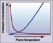
Figure 1. CO levels (red) rise as flame
temperature decreases. Increasing the fuel-to-oxidizer ratio leads to higher flame temperatures (blue) and higher NOx |
The dependence of NOx and carbon monoxide concentrations on flame temperature are shown for lean flames in Figure 1. At very lean conditions, the flame temperature is not sufficiently high to completely burn out CO, and CO levels rise rapidly as the flame temperature decreases. As the fuel-air mixture is made increasingly lean, it approaches the lean blowout limit where the flame does not release sufficient heat to sustain itself. On the other side of the graph, flame temperature, and NOx, increase as the fuel-to-oxidizer ratio increases.
Low-NOx burner design
Low-NOx burner design involves several factors. One factor is to establish mixing of the air and fuel before they flow into the flame zone, so the flame burns at a uniform and well-defined temperature. If air and fuel are poorly mixed, there will be fuel-rich regions and fuel-lean regions within the flame zone. The fuel-rich regions will burn with a high flame temperature, generating excess NOx, and possibly burning incompletely due to excess fuel. The fuel-lean regions will not generate much NOx, but may burn at too low a temperature for complete combustion.
An effective gas-mixing system should be integrated into a low-emissions burner design, but the creation of a volume of mixed fuel and air in the burner upstream of the flame zone can introduce some safety concerns. Proper control of the flame position must be maintained to avoid the flame flashing back to the fuel injection zone. The fuel injection system should be insensitive to pressure fluctuations in the flame zone to avoid combustion oscillations.
Premixed burners can often operate effectively over a range of lean equivalence ratios. For maximum efficiency, the burner should be set to operate at the highest flame temperature that will produce acceptable NOx emissions and will not damage the downstream section of the combustion system.
One advanced premixed burner design that is capable of very low-emission operation is the low-swirl burner (Figure 2). The low-swirl burner is a scalable design that has demonstrated excellent operating stability while achieving low-emissions performance. The concept was developed as a flame research tool by one of the authors (Robert Cheng), and is used for industrial heating applications.*
 |
|
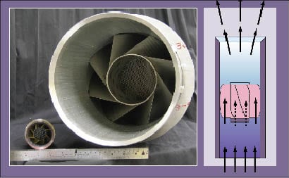
Figure 2. With a series of vanes at exit angles of about 35–40 deg, the low-swirl burner
splits the flow of incoming air into a non-swirling center surrounded by a swirling annular flow |
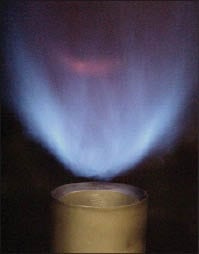
The low-swirl burner splits the flow of incoming air into a non-swirling center flow surrounded by a swirling annular flow. The swirl in the annular region is generally created by a series of vanes with exit angles of about 35–40 deg. The interaction of the flows at the exit of the swirler assembly creates a flow profile that expands radially outward. This interaction causes the axial flow velocity to ramp down as the flow expands outward (Figure 2, diagram). This velocity downramp creates the unique flame stabilization mechanism of the low-swirl burner. Once the burner is lit, the flame settles in the region downstream of the swirler exit, where the flow velocity matches the turbulent flame speed of the fuel-air mixture (Figure 3). The burner design can accommodate fuels with a wide range of flame speeds. The flames of fuels with high flame speeds, such as hydrogen, will burn close to the burner exit, while the flame of low-heat-content fuels, such as landfill gas (with low flame speeds) will settle at a lower velocity region farther from the burner exit.
 |
Low-swirl burner and flex-fuel
Development of fuel-flexible combustors (also referred to as injectors) in turbines for electricity generation is an important potential application for integrated-gasification combined-cycle (IGCC) power plants. As an example of the process required to modify burner designs for operation with alternative fuels, we discuss an investigation adapting the low-swirl burner for operation with both natural gas and syngas in power turbines. With U.S. Dept. of Energy support, research is underway to explore design concepts to adapt the low-swirl-based combustor for turbines that will allow operation with natural gas, medium-hydrogen-content (unshifted) syngas, and high-hydrogen-content fuels.
What are the most important issues associated with designing a turbine combustion system that can operate efficiently and cleanly on multiple types of fuel? The following issues should be considered: First, compare the properties — such as heat content, density, flame speed, range of flammability and autoignition temperature — of the fuels to be used.
One parameter that is used to assess fuel interchangeablity is the Wobbe Index (W.I.), which is defined as the higher heating value divided by the square root of gas specific gravity. The W.I. is helpful in assessing fuel supply and control issues for a combustion system, but it does not address the combustion properties of the fuels. Wobbe Index values for natural gas, hydrogen, and medium hydrogen syngas and high hydrogen syngas are listed in Table 1. Natural gas and hydrogen have similar W.I. values, but the syngas blends are significantly different. This indicates that the fuel circuit in a natural gas combustor could be used for hydrogen, but a different fuel circuit would be needed for the syngas blends.
| Table 1. Properties of potential fuels for a gas turbine in an IGCC plant | ||||
| Natural gas | 100% H2 | Medium H2 | High H2 | |
| Specific gravity | 16.4 | 2.0 | 20.6 | 7.3 |
| Molecular wt., kg/kmol | 0.54 | 0.07 | 0.71 | 0.25 |
| Density at std. temp. and pressure, kg/m3 | 0.65 | 0.08 | 0.86 | 0.30 |
| Lower heating value, kJ/kg | 47,450 | 120,580 | 11,193 | 27,842 |
| Lower heating value, kJ/m3 | 32,676 | 10,059 | 9,687 | 8,457 |
| Wobbe Index, MJ/m3 | 44.2 | 38.3 | 11.4 | 17.0 |
The combustion properties of the fuels add another layer of complexity to the analysis. The specifications of a 200-MW (F class) power turbine will be used to investigate the operating conditions for a conceptual turbine combustor based on the low-swirl design. The airflow from the turbine compressor is roughly constant at full load. The turbine combustor will have a well-defined heat release, and this value can be used to determine the fuel flowrates. Selected values for operating parameters are listed in Table 2. Flame temperature will be constrained by NOx production and should be about 1,840K to achieve single-digit NOx emissions. The primary zone refers to the flame region. A portion of the incoming air is split off before the combustor and injected downstream of the flame to reduce the temperature to about 1,700K, the upper limit for the turbine inlet temperature. The flowrate of unshifted (medium-hydrogen) syngas is substantially higher than that of other fuels.
| Table 2. Power turbine operating parameters for natural gas and two syngases | |||
| Natural gas | Medium H2 | High H2 | |
| Fuel temperature, K | 458 | 366 | 366 |
| Primary zone temperature, K | 1,839 | 1,839 | 1,842 |
| Mass flow (fuel), kg/s | 12.4 | 57.1 | 22.4 |
| Mass flow (air), ks/s | 382 | 382 | 382 |
| Primary zone fuel-to-air | 0.032 | 0.149 | 0.059 |
| Total mass flow, kg/s | 466 | 511 | 476 |
| Normalized mass flow | 1.00 | 1.13 | 1.05 |
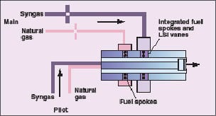
The values in Table 2 can be used to develop a conceptual combustor design that can utilize all of the fuels of interest. The flowrates and the fuel combustion properties suggest that it would be difficult to use a common fuel system for all three fuels. By incorporating two fuel circuits in the combustor assembly, it will be possible to operate the turbine at full load with any of the fuels and switch between fuels without shutting down (Figure 4). The flowrate of medium-hydrogen syngas will require a supply system with a larger cross-section than natural gas. High-hydrogen syngas can be supplied at a lower pressure than the medium-hydrogen syngas to provide a suitable flowrate through the same circuit.
 |
|
Figure 4. Incorporating two fuel circuits in the combustor assembly allows
operation of the turbine at full load with any of the fuels, and switch between fuels without shutting down |
Since hydrogen-containing fuels are more susceptible to flame flashback and autoignition, the injection site for these fuels is placed as close as possible to the combustor exit. This arrangement minimizes the volume of mixed air and fuel upstream of the flame zone. The natural gas injection site can be optimized for natural gas injection and located upstream of the syngas injection site. The dual-fuel-channel concept will minimize the modification of the low-swirl injector design developed for turbines, provide acceptable fuel injection pressures for all fuels and will allow seamless transition between fuels.
At present, only a conceptual design for a fuel-flexible, low-swirl combustor for power turbines has been developed. Considerable development and testing will be required to establish a geometry that will satisfy all of the requirements of such a burner. There are a number of potential issues to be explored, including:
• Fuel injection and mixing
• Variations in flame speed and flammability with fuel composition
• Flame behavior during transition between fuels
• Turbine instabilities and oscillations
• Cooling and temperature control of the combustor hardware
Coal gasification
Net carbon emissions can be reduced by using fuels from renewable sources or by removing carbon from the fuel stream (either before or after the combustion system). Lowering carbon in the fuel stream has focused attention on hydrogen as a fuel. Hydrogen can be produced by the gasification of coal.
The U.S. is one of a number of regions throughout the world with abundant coal reserves. To reduce the emissions and carbon footprint from coal-based power generation, pilot-scale studies are underway to gasify coal in IGCC plants. Coal gasification systems heat coal with steam and limited amounts of oxygen or air to yield a syngas that consists primarily of CO, CO2 and H2. The syngas can be processed by the so-called water gas-shift reaction to generate a mix of primarily H2 and CO2 (CO + H2O —> CO2 + H2).
The high-hydrogen-content syngas can be burned in a gas turbine to generate electricity. It is highly desirable to be able to burn natural gas in the turbine when syngas is not available.
The high concentration of carbon dioxide in the mix simplifies capture of CO2 for sequestration or other purposes, such as enhanced oil recovery. Capturing CO2 takes energy, so the goal is to establish a high concentration of CO2 in the gas stream before separation. There is also an increasing emphasis on improving system efficiency so that more useful energy is extracted for a given quantity of fuel burned.
 |
|
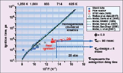
Figure 5. If fuel is injected into air at conditions suitable for autoignition, there is a time delay
before ignition occurs. Experiments and models of ignition delay disagree |
Autoignition in hydrogen-containing fuels is a concern at turbine operating conditions, and continues to be an area of active research. While hydrogen does not have a particularly low autoignition temperature, it has a very low ignition energy. The conditions at which autoignition occurs depend on a number of factors, including the composition of the fuel, the fuel-to-air ratio, pressure and temperature. If fuel is injected into air at conditions suitable for autoignition, there is a time delay before ignition occurs. There is disagreement between experiments and models of ignition delay (Figure 5).
To avoid the possibility of autoignition in a combustor, the residence time for the airflow to pass from the fuel injection point to the flame zone should be kept as short as possible when operating on fuels with high hydrogen content. The design goal for the low-swirl injector, for example, is to keep the residence time below 5 ms, which should supply a suitable safety margin at typical turbine operating conditions.
*Note: The low-swirl burner design has been licensed by Honeywell’s Maxon Corp. (Muncie, Ind., www.maxoncorp.com) for process heating over a specific heat-output range and was commercialized for natural gas operation. The low-swirl burner technology is available for licensing for other applications.
Author

David Littlejohn is a staff scientist in the Environmental Energy Technologies Division at the Lawrence Berkeley National Laboratory (One Cyclotron Road, Mail Stop 70-108B, Berkeley, CA 94720; Phone: 510-486-7598; Email: [email protected], Web: www.lbl.gov.) Littlejohn and colleagues conduct research on the development of fuel-flexible combustion systems with ultralow emissions for power turbines and industrial process heating systems. He has a Ph.D. in chemistry from the University of California at Berkeley.

Robert K. Cheng is a senior scientist and leader of the Combustion Research Group in the Environmental Energy Technologies Division at Lawrence Berkeley National Laboratory. He has a Ph.D. in mechanical engineering from the University of California at Berkeley. His research interests are on premixed turbulent flames and their adaption to low-emissions heating and power systems.

Kenneth Smith is presently an independent consultant in the area of advanced combustion technologies for industrial gas turbines. Previously, he was employed at Solar Turbines Inc. for thirty years where his work focused on the development of low emissions combustion systems. Smith earned a Ph.D. in mechanical engineering from Cornell University.

Peter L. Therkelsen is a postdoctoral research associate at Lawrence Berkeley National Laboratory. He has a Ph.D. in mechanical and aerospace engineering from the University of California at Irvine. His research interests are in combustion and energy analysis.

Sy Ali is the principal of Clean Energy Consulting, a contractor for the U.S. Department of Energy. He has held management positions at Rolls Royce, General Motors, Duke Energy, and General Electric. Dr. Ali received his Ph.D. from Michigan State University and is a registered professional engineer.