Follow this guidance to make the most of engineering upgrades that are designed to improve plant operations or boost throughput capacity
The chemical process industries (CPI) are functioning in an era of globalization, and between the prevailing economic conditions and upheavals in the energy sector, the number of new investments in CPI facilities has fallen in recent years. Many industries are seeking cost reductions by revamping existing plants with minimum investment. The objective is to reduce the cost of production through the use of upgrades and new technologies, to remain competitive in the market. By way of example, if one wants to set up a new complex to produce ammonia and urea, the specific capital cost will be on the order of $666/ton of urea. By comparison, if an existing plant is revamped to raise the existing production from 100% to 120% (that is, adding 20% additional capacity), this can be done at an expenditure that is closer to $300/ton to achieve this incremental production
This article reviews key concepts, objectives and procedures that are needed to successfully carry out various types of CPI plant revamps.
The need for revamps
Chemical process plant revamps are typically undertaken for the following reasons:
- To change in feedstock composition
- To adopt energy-conserving processes in light of increasing energy costs
- To reduce the fixed-cost components of production, by increasing capacity within the existing facility
- To extend the life of a well-maintained process plant
Similarly, there are many benefits to conducting an appropriate plant revamp. These include the ability to:
- Increase the reliability of equipment, leading to reduced downtime and maintenance costs
- Reduce energy consumption
- Extend useful plant life
- Reduce the cost of production, thereby improving the overall bottom line for the facility
However, experience shows that inefficient implementation of proposed revamp options can lead to failure, so care must be taken to avoid this by building the right team of experts. This team typically includes representatives of the process licensor company, engineering and project-management consultants, and experts from the owner company representing diverse fields, such as operations, project management and maintenance. If sufficient expertise for the proposed revamp is not available internally, one can hire consultants to carry out the feasibility studies and implementation of the revamp on a turnkey basis. Meticulous planning related to the hook-up of tie-in points arising out of expansion schemes can help to reduce the amount of downtime required to execute the revamp schemes and put the plant back online.
Targeted revamp capacity, change in process
In general, it is possible to increase the rated capacity of a plant by 10%, with very little added expenditure. But to increase capacity by 20–50% over the nameplate capacity, substantial modifications must be taken into consideration that often involve implementing different technologies from the ones already applied in the existing plant. When seeking such notable increases in production capacity, plant operators and managers must not only verify the soundness of the economics, but also carefully evaluate the potential drawbacks, if any.
Sometimes the existing process path may have to be changed to enhance the capacity of the plant, since the current process may not yield the desired efficiency or conversion rates. Two cases are discussed below.
Example 1. In the case of units to recover liquefied petroleum gas (LPG) from natural gas, such units are designed for a certain composition of feed gas. The need for a revamp often arises if the gas composition has changed and the expected recovery of C3/C4 and higher compounds has become unprofitable. In this case, the expected recovery of LPG and natural gas liquids (NGLs) can be achieved by compressing the feedstock to higher pressures than present levels, or by spiking heavier NGLs back to the feed gas stream. Thus, such a revamp requires a study to assess the technical and economic feasibility of the different process paths being considered.
Example 2. A feedstock change from naphtha to natural gas in ammonia plants, hydrogen plants and methanol plants also necessitates a need for revamp of the reformer section and front end, but in many cases, the existing process path can be retained. In this case, the absorbed duty of the reformer — which tends to be the major energy-consuming equipment found in the system — and the burner duties required vis-a-vis the required reformer absorbed duty are calculated to check their suitability. The maximum skin temperature of the reformer tubes for the feedstock change must be checked.
In all cases, the existing process path, along with other options, must be studied in detail to arrive at the most economical and technically feasible revamp option.
Lifecycle of the plant
The different phases of a plant’s lifecycle must be taken into consideration when planning a revamp. Such phases include the following:
- Incubation stage — Initial stabilization period
- Growth stage — Optimization and debottlenecking of operations to improve the efficiency
- Maturity stage — Attainment of stable operation
- Declining stage — Realization that plant capacity is not sustainable because of frequent equipment failures or excessive maintenance requirements
Revamping the plant during Phases 1, 2 or 3 is relatively easy, whereas revamping a plant during Phase 4, when the facility is already in decline, requires the engineering team to adapt many of the modern technology options to an aging infrastructure, and to replace many equipment components.
Objectives of a revamp
The objectives of a plant revamp should be spelled out prior to studying the options. Possible objectives could be the following:
- Enhance capacity from the present operating level to expand capacity to, say, 110%, 120%, 130% of rated capacity
- Reduce production costs
- Reduce pollution
- Reduce the consumption ratios of various raw materials and utilities
- Reduce maintenance costs and increase the onstream factor
- Upgrade the technology to keep pace with the new developments, and to increase the plant life
- Minimize plant shutdown
These objectives can be achieved by maximizing efficiency, yield and conversion of raw materials in various sections. Specifically, plant revamps are often implemented to improve process optimization, increase energy conservation, improve product quality and expand capacity.
Key revamp procedures
Every revamp project should start by identifying the goals and actual bottlenecks. A material-and-energy balance for the base case should be developed to reflect the actual operating conditions. The consumption of various raw materials, utilities and energy per unit of production are tabulated. The material-and-energy balance of the existing operation, and the required revamp plant load, are prepared.
The existing equipment components are rated for the revamp conditions, and then changes and required new equipment are identified. Cost estimates of various schemes are prepared (after consultation with various vendors). Feasibility studies, followed by detailed project reports (DPR), are also prepared. The potential rates of return of various options are studied. The best option available (on the grounds of economic sustainability and technical feasibility) is then selected, so that the basic engineering design package (BEDP) can be prepared, and the revamp project implemented.
As noted, successful revamps require assembling the right revamp team. Typically, such a team consists of individuals from the process licensor company, consultants for basic engineering and detailed engineering services, contractors for specific electrical-, mechanical- and instrumentation-related aspects of the project, and various engineers from the owner’s group (for instance, those who represent specific disciplines and have a concrete understanding of the current operation).
The following planning steps should be undertaken:
- Estimate the plant’s inherent capacity from past and recent data. This can be done by identifying weak areas in the plant (for instance, those that are contributing to non-realization of rated or required plant capacity), or by conducting an end-to-end survey of the plant. Once such a study is carried out, efforts should be made to predict the potential performance improvements of the plant if the weak areas are rectified.
- Prepare the process scheme and the equipment data sheets. Carry out feasibility studies of all options (including both technical and financial aspects of the proposed revamps) and then develop the detailed project report. Set the target of the revamp in terms of time (schedule) and cost.
- Implement the approved revamp. Ideally, the revamp activities should be carried out during the annual scheduled turnaround period for the plant, to minimize unscheduled downtime.
Estimate plant capacity
Many older CPI plants can run at or above the rated capacity continuously for a week or a month. But due to certain operating limitations, and downtime that may arise from some underperforming equipment, the annual rated capacity is seldom achieved. Analyzing past operating data on a monthly basis (for the past 10 years or so) will reveal which equipment components are most often to blame for downtime, and are thus affecting overall capacity utilization. Such a study of past data is often called a weak-area analysis. Similarly, sometimes an end-to-end survey of the plant (from the plant commissioning to the present day) is also conducted.
Existing equipment poses both opportunities (in the form of underutilized capabilities) and challenges (in terms of limitations). The ability to identify problem areas can help the team to prioritize their debottlenecking efforts in order to improve capacity utilization more quickly.
The weak-area analysis
Understanding current operation is very important for the successful revamp of a plant. The plant performance can be evaluated based on the performance data for the past 10 years, if the plants are relatively old. Otherwise the plant performance is studied from the beginning to the present day (using the end-to-end survey).
Two indices, the plant load factor (PLF), and the onstream factor (OSF), are important to scientifically evaluate the plant performance.
![]() ( 1)
( 1)
![]() ( 2)
( 2)
![]() ( 3)
( 3)
![]() ( 4)
( 4)
The performance of the plant is studied based on the highest PLF and OSF, on both a yearly and monthly basis. Data on the highest daily production that is achieved with the present hardware should also be captured.
In addition to the past production performance of the units, a breakdown of individual equipment must be assessed to identify the weak areas and arrive at the predicted performance in the post-revamp implementation scenario. The best yearly, monthly and daily performance must be considered in order to find the target capacity of the plant and identify the number of stream days that this target capacity is likely to achieve.
Analysis of historic downtime factors can also provide insight. To assess the feasibility of the plant operating at higher capacity, the best-achieved PLF (on a monthly basis), and the highest load achieved, should be considered.
In any process plant, onstream days are lost due to various factors — including process problems, mechanical breakdown of equipment, raw material shortages, planned shutdowns, finished product sales, effluent treatment and byproduct sales (if any). Such lost days — which contribute to a loss of overall capacity utilization — should be tabulated, and the associated causative factors noted and tabulated.
From the weak-area analysis, one can estimate the inherent capacity potential of the plant and identify individual equipment components or sections that are becoming a bottleneck to maximum capacity utilization. Sometimes the plant capacity is affected by external circumstances, such as feedstock supply issues (for instance, urea plant capacity is impacted by the capacity of upstream ammonia plants) utility supplies and more.
Dividing these factors into recurring and non-recurring factors will also provide insight into the priorities needed to address the problem.
- Internal reasons: Recurring. Examples include process problems, mechanical breakdown of equipment, planned shutdowns and more
- Internal reasons: Non-recurring. Examples include lack of finished product sales, effluent treatment, lack of byproduct sales and more
- External reasons: Recurring.Examples include utility failure, raw-material shortages and more
- External reasons: Non-recurring. Examples include worker strikes, natural calamities and more
FFS and RLA analysis
In a chemical process plant, critical equipment and piping must be evaluated for their fitness for service (FFS), according to API 579 [ 1 ], and their potential residual life analysis (RLA) must also be assessed. The API 579 guidelines are designed to ensure that pressurized critical equipment are operated safely. The ability to establish the minimum years of residual life of the critical equipment is essential to justify the revamp of the old and well-maintained plants.
Use of simulation software
Simulation software can play an important role during the evaluation of potential revamp options, so its use is recommended to study the competing process-revamp options. Such modeling can help the team to substantially reduce the time needed to study the technical feasibility of revamp options. However, great care must be taken to ensure the use of most appropriate thermodynamic modeling options that are suitable for the plant and its components, fluid properties, process conditions and so on; otherwise the results can be wrong. Appropriate use of simulation software can reduce the time required to carry out the revamp projects, and help the team to identify an optimized, cost-effective process path, based on an evaluation of proposed process sequence changes given the various constraints.
The various revamp options are studied from a technical and financial point of view, a suitable process path is selected and the equipment that create a bottleneck for the desired revamp option are identified. Once the additional equipment and piping are identified (per the proposed expansion schemes), the required hookup points and tie-in connections must be identified. As noted, to reduce the impact of these hookups, they should — wherever possible — be undertaken in conjunction with short shutdowns that are planned for preventive maintenance.
Environmental and safety impacts
Environmental-impact assessment studies should be conducted during the conceptual stage to evaluate the positive and negative impacts of the proposed engineering changes on the environment, and to arrive at the solutions to mitigate the adverse impacts, if any.
Safety is always a paramount consideration. The team must ensure that the proposed plant revamp, and all revised process schemes, conform to the latest codes and safety norms. Hazard operability (Hazop) studies of the process schemes during the basic engineering-design package stage, front-end engineering-design stage, and the detailed engineering stage should be conducted. During the implementation stage, periodic technical audits should be conducted to see that the construction is progressing according to design intentions.
Hazardous-area classification drawings of the plant are developed, and existing electrical considerations and other instruments are evaluated and changed according to the modified hazardous area classification of the plant. Quantitative risk analysis (QRA) is also conducted to submit to the statutory authorities, and any onsite and offsite emergency plans must be revised, as needed.
Similarly, a safety integrity level (SIL) analysis should also be conducted according to BS IEC 61511[ 3 ] and BS IEC 61508 [ 4 ]. And, all safety-instrumented functions (SIF) of the instruments are to be SIL 2 (minimum).
Debottlenecking individual equipment systems
Different strategies are available to debottleneck different equipment components and systems. Some examples are discussed below:
Trayed columns. The design data of the distillation column should be studied, preferably using process simulation software. The column is simulated for both the existing operating conditions, and for desired higher throughput or changed feed composition. The liquid and vapor rates for each tray, along with their physical properties, are obtained. After obtaining the column profile and liquid-vapor-traffic details in the column, the tray hydraulics are calculated and suitable recommendations are made, regarding changes made to the weir height, the number of holes, pitch, the diameter of the holes (considering the flooding conditions) and more. Tray vendors should be contacted when considering revamping the distillation column trays. The team should ensure that the reboiler and condenser are rated for the maximum throughput expected.
Many advanced separation technologies that are available today allow for higher-capacity trays to be retrofitted into distillation columns. Similarly, the suitability of advanced structured packings can also be considered when planning a revamp of distillation columns in petroleum refinery and other critical CPI applications. Many present-day structured packings can help revamped columns to improve capacity by 40–50%, while reducing pressure drop across the column.
Packed columns. In the late 1980s, Raschig rings were popular in chemical process operations. A study of pressure drop of the packed column at the rated capacity should be carried out to determine the pressure drop per foot of packed column. Such a study should also identify the percent flooding velocity with the revamped throughput. If the flooding velocity is greater than 80%, the packings are replaced with ones that offer lower packing factors and higher surface area per specified volume. However, adequate wetting of the packing must be ensured, according to design guidelines, and circulation rates of liquids must be enhanced accordingly, if needed.
Packed towers that contain ceramic packings have a tendency to flood at lower gas velocities. Hence, in some cases, such packings may be replaced with steel packings (after conducting the technical suitability check) to help reduce the flooding velocity and increase throughput.
Pumps. Pumps are very important and often provide a relatively simple revamp opportunity, to take advantage of advancements in pump technology. The throughput required at desired plant capacity is determined, and the characteristic head-versus-capacity curves, required net positive suction head (NPSH), and other key characteristics should be studied. Normally, pump manufacturers indicate three impellers (minimum, normal, maximum) that are suitable for any duty. The possibility of using a larger-sized impeller diameter should be studied, considering the head and capacity requirements (Figure 1).
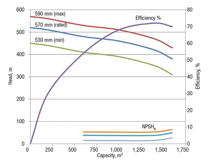
FIGURE 1. Shown here are typical pump characteristic curves, with three different impeller sizes, showing capacity versus head, and NPSHR versus capacity
As the pump capacity increases, required NPSH (NPSHR) increases. Hence, the available NPSH (NPSHA)should be checked, to avoid cavitation of the pump at higher flows. The motor’s suitability should also be verified. Many successful revamps were carried out by changing the impellers to those with larger diameters. The team should also carry out a design check to ensure that the piping material classification is still suitable for the pump’s discharge piping.
Instruments. Instruments such as flowmeters (orifice, venturi and mass flowmeters), pressure indicators, temperature transmitters, level instruments and so on should be rated and studied in detail for the proposed changed condition. Since orifice meters often give rise to higher pressure drop, they may be replaced with mass flowmeters. Similarly, level instruments based on differential pressure can be replaced with non-contact type, radar-type level instruments, which tend to be more accurate.
Normally, the orifice plates in flowmeters are maintained with ratios — that is, the ratio of orifice plate bore diameter ( d) to pipeline diameter ( D) — of 0.3 (minimum) to 0.7 (maximum). The orifice meters are rated for the target throughput and the pressure drop across the orifice element is determined. If the pressure drop is too high, the orifice plates are changed to those of higher ratios, to address the pressure drop issue without changing the transmitter. To keep the ratio less than 0.7 for a given pressure drop across primary element, either or both the orifice plate and the transmitter is changed.
Control valves.The flow through a control valve depends on its capacity, or so-called C V value (Equation 5), which is defined as the flowrate in m3/h of water at a temperature of 60°F with a pressure drop across the valve of 1 psi. The rule-of-thumb rule is that the C V is roughly 10 D 2 (where D is the size of the control valve in inches). For example, the C V of a 2-in. control valve is roughly 40. The C V value is recalculated according to ISA 75.01.01[ 2 ] with the new flowrate, inlet pressure and allowable pressure drop.
Normally, the control valves in the original design of the plant are kept one size lower than the pipe line diameter, and their rated flow is specified as 1.7 times the normal target flow, or 1.3 times the maximum target flowrate. Since the flowrate is specified as 70% higher normal flowrate, or 30% higher maximum flowrate, the control valves will be suitable to handle the revamped target flow, which is 20–30% more than the design flowrate. Hence, for a proposed 20–30% plant load increase, the existing control valve will normally be sufficient. If the C V of the control valve is not sufficient, the team may consider either changing the trim of the control valve, or installing one with a higher C V. Equation 5 is used to calculate the C V .
![]() ( 5)
( 5)
Where:
Q = the flowrate through the control valve, m3/h
N 1 = a constant (8.65 x 10⁻²), from ISA 75.01.01-2007 (IEC 60534-2-1 Mod), Table 1 [ 2 ]
1 = density of the fluid, kg/m3
0 = density of the water at 15°C, kg/m3
P = differential pressure, kPa
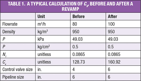
Table 1 shows a typical calculation of C V before and after revamp flowrates, and shows how the existing control valve must be changed to the pipeline size for a 20% increase in flowrate.
Control valves should also be checked for noise levels. Controllability and rangeabilty are also important for revamping the valve. Revamps involving control valves should always involve vendor cooperation. If the revamp is not able to bring the process into the controllability range, either the valve should be replaced with one of higher size, or fine feed-control valve can be added parallel to the existing control valves.
Heat exchangers.The existing heat exchangers should be checked for any excess available surface area, by rating them using standard software modeling packages. In general, an existing heat exchanger provides enhanced heat exchanging capacity if the pressure drop across the tube side or shell side is increased.
If the heat exchanger is downstream of a pump, the team should consider increasing pump head, which would increase the allowable pressure drop across the heat exchanger. There may be a tradeoff between the operating cost of the pump and fixed cost associated with changing the heat exchanger. Also, increasing the number of baffles on the shell side to increase the heat transfer coefficient should be considered. In the case of plate heat exchangers, additional plates can be added to increase the heat transfer, in consultation with original equipment manufacturer.
Limitation in line sizes.All of the line sizes are checked using the standard velocity criterion. Typical standard velocity criteria are shown in Table 2.
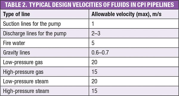
The lines are checked for pressure drop. In case the line pressure drop is high, the lines are changed to provide larger-diameter pipes. Special attention must be given for gravity-flow lines, as the allowable velocity is in the range of 0.6–0.7 m/s and sufficient slope must be ensured.
The piping material thickness (according to ANSI B 31.3) and flange ratings (ANSI B16.5) are checked to be sure they comply with higher pressure. In some cases, the flange rating will be sufficient, as there is often a wide margin available, as shown in Table 3.
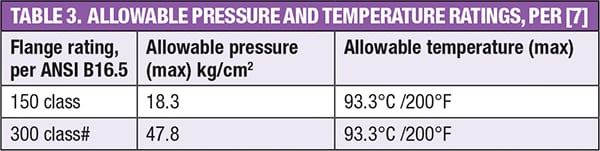
Thus, if a line that was designed for 10 kg/cm2 is going to experience a pressure of 12 kg/cm2 at 90°C, then the flange rating of 150# need not be changed. However, the actual pipe thickness should be measured and checked for its suitability in the revamped design pressure condition. Sometimes no piping needs to be changed — for instance, if the design pressure in the revamped condition is less than that of the original process. One example is an ammonia synthesis section, where pressures have come down from 200 kg/cm2to 140 kg/cm2.
Pressure safety valve (PSVs). When the plant runs at higher revamped capacity, all of the PSVs must be checked according to API 520 [ 5 ]. The team must evaluate the nozzle area suitability and the rating of the inlet and outlet piping, after recalculating the fluid-relieving rates associated with the new throughput. PSVs are changed if they are found to be unsuitable. In the case of feedstock changeover, PSVs must be also be checked for changes in fluid properties such as molecular weight, compressibility factors and so on.
Compressors.Various options for revamping the compressors should be studied initially. Various revamp options include the following:
- Installation of a suction booster
- Installation of a parallel compressor
- Changing internals in the low-pressure and high-pressure casing, along with steam turbine upgrading
- Providing a chiller at the suction inlet and changing the intercoolers. A chiller can be installed to reduce the gas temperature and increase the volumetric capacity of the gas and reduces the power requirement. In cases where the drive needs to be changed, this can be applied.
- Change of compressor type. In older-generation urea plants, urea reactors operated at 200 kg/cm2, and they fed the CO2 to the urea reactor; Historically, CO2 compressors have been reciprocating-type, which incur high energy costs. As the pressures in present-day urea reactors have come down to 135 kg/cm2, centrifugal compressors can be used instead, which helps to reduce operating costs as well as maintenance costs).
Effluent treatment plants (ETP).Worldwide, wastewater-treatment plants are typically designed with high safety margins, to cater to shock loading or sudden peak loading of effluents containing high chemical oxygen demand (COD). However, when a plant is stabilized and optimized, the generation of wastewater containing high COD is drastically reduced.
The following methodology should be adopted while checking the capacity of ETP that are based on an activated sludge process during revamp planning:
- Evaluate existing facilities by collecting operating data for one month and developing a statistical analysis of various parameters.
- Check the design basis and the design volume of the aeration basin, thickener and clarifier.
- Evaluate the operating case using the above design basis.
- Calculate the energy requirements of the design and operating cases, and quantify the potential for reduction of electrical energy at various loads.
Flares and knockout drums.Flare systems, including knockout drums, must be checked before embarking on a plant revamp. Flares are used to ensure plant safety, by flaring hydrocarbons in case of emergency conditions such as power outages, fire or blocked discharge.
While converting the ammonia plant from a liquid fuel (such as naphtha) to natural gas, the properties of the fluid (such as molecular weight, compressibility factor), viscosity and density undergo a drastic change and have profound effects on height, flare diameter and flare tip suitability. Calculations must be performed to verify the new case, according to API 521[ 6 ]. The goal is to see whether the existing flare is suitable to handle the changed load and fluid conditions associated with the proposed revamp. Vendor support should be sought, if needed, and the flare design can be checked using manual calculations, spreadsheet calculations and flare-specific computer software.
Reactors.Reactors are the heart of chemical process operations. Efforts should be made to maximize yield and conversion rates in the revamp scheme. If, following the reaction, raw materials remain unconverted, they must be separated and recycled back to the reactors. This consumes utilities, thereby increasing energy consumption. If conversion rates in the reaction are increased via a revamp, the recycle ratios will be drastically reduced.
In one urea plant, a revamp involved the following changes: Introduction of higher-capacity trays in the urea reactor in the ammonia plant; changing the converter baskets from axial- to radial-type in the ammonia converter in the caprolactam plant; using an enriched-oxygen supply to the cyclohexanone reactors with introduction of improved safety features. These changes were able to increase the conversion rate, increase overall production and decrease energy consumption.
In the ammonia plant’s synthesis section, the synthesis converter pressures were reduced to 135 kg/cm2(from an initial level of 200 kg/cm2), as a result of the introduction of radial basket converters instead of the older-generation axial converters. By retaining the same high-pressure converter shell, one can change the converter baskets to radial ones, which helps to reduce pressure drop.
Catalysts play a vital role in enhancing the reaction rate. The use of advanced catalysts should be considered, where possible. For example, in sulfuric acid plants, vanadium pentoxide (V2O5) is typically used as a catalyst. If an improved cesium catalyst is added to the reactor, the SO2 to SO3 conversion can be increased, and the emission of SO2 can be reduced, generally to far below the statutory limits.
Storage tanks. If the process revamp is based on a “more in/more out” concept — that is, more fluids will be flowing into and out of storage tanks — then the team must check the capacity of “breather” valves and emergency vents according to API 2000 [ 8 ]. If the breather valves need to be replaced, the pressure settings may be adjusted in consultation with vendors, according to the applicable codes.
Utilities. During any plant revamp, the capacity of key plant utilities, such as demineralized water, instrument air, plant air, steam plants, power, and cooling tower should also be checked to be sure they will support the proposed revamp. Offsite facilities related to raw-materials receiving, tank farms, and product-storage capacities must also be studied and related personnel requirements must be ascertained. n
Edited by Suzanne Shelley
References
1. American Petroleum Inst., API 579: Recommended Practice for Fitness for Service, 2nd Ed., July 2007.
2. Instrument Soc. of America, ISA 75.01.01-2007 (IEC 60534-2-1 Mod): Flow Equations for Sizing Control Valves, 2007.
3. International Electrotechnical Commission (IEC), BS IEC 61511: Functional Safety – Safety Instrumented Systems for the Process Industry, 2003.
4. International Electrotechnical Commission (IEC), BS IEC 61508: Standard for Functional Safety of Electrical/Electronic/Programmable Electronic Safety-Related Systems, 2010.
5. American Petroleum Inst., API 520: Sizing, Selection and Installation of Pressure Relieving Devices, Part 1, 8th Ed., 2008, and Part 2, 5th Ed., 2003.
6. American Petroleum Inst., API 521: Pressure Relieving and Depressurizing Systems, 5th Ed., 2007.
7. ASME/ANSI B16.5: Pipe Flanges and Flanged Fittings, April 2013.
8. American Petroleum Inst., API 2000: Venting Atmospheric and Low Pressure Storage Tanks, 7th Ed., March 2014.
Author
 Koya Venkata Reddy is senior manager, process engineering, at FACT Engineering & Design Organization (FEDO), a div. of Fertilizers and Chemicals Travancore Ltd. (FACT; Udyogamandal 683501, Kochi, Kerala, India; Phone: +91-484-2568763; Email: [email protected]). He has 24 years of experience in chemical plant operations, including expertise in the fields of process control, process design, process risk analysis, Hazop analysis, process simulations, environmental management and plant revamps. He is a recipient of FACT’s Merit Award. Reddy holds a Bachelor of Technology degree from Andhra University (Visakhapatnam) and a Master of Technology degree in project management from Cochin University of Science and Technology. He also received an M.B.A. in finance from Indira Gandhi National Open University (IGNOU; Delhi). He is a lifetime member of the Indian Inst. of Chemical Engineers (IIChE) and a member of the Institution of Engineers (India).