The combination of advanced materials and processing techniques results in new composites that can aid industries in achieving increased levels of efficiency
By their nature, composite materials lend themselves to a vast array of applications. A composite’s constituent materials and processing methods can be tailored to yield seemingly infinite combinations of physical and chemical properties. Although composites have long been essential in countless industries, technological advances continue to expand their reach, and industries are increasingly seeking out cutting-edge materials to increase operations’ sustainability. This article focuses on innovative composite materials and processing techniques designed for use in two major industries where sustainability and efficiency are key — wind power and aerospace.

FIGURE 1. As wind power becomes more universal, the manufacturing processes for turbine components must also grow
more efficient
Elevating wind turbine efficiency
A major application area for composite materials is in wind turbines (Figure 1). With the push for more renewable sources of energy, wind-farm construction has intensified in recent years. Wind turbines must be able to withstand continued operations in extreme heat, freezing temperatures, precipitation, lightning, and of course, high winds. Composites’ versatility and strength make them well suited for these environmental demands. Furthermore, the composite materials used for turbine components can actually make the overall turbine-manufacturing process more efficient.
Although many parts of a wind turbine, including the nacelle (the enclosed box that houses the various generating components) and spinner, can be constructed of composite materials, composites are mainly used for the rotor blades. “They have to be light, stiff, long-lasting and need to resist environmental influences,” says Johannes Moser, R&T manager at Hexcel Corp. (Stamford, Conn.; www.hexcel.com). Hexcel’s portfolio consists of epoxy-resin composites reinforced with glass or carbon fiber for high fatigue resistance. Since rotor blades can be massive structures, they must be produced in a very efficient manner, and the composite material’s properties and handling requirements must withstand the rigors of the rotor-manufacturing process. “To develop an epoxy resin for wind-energy applications, the reaction enthalpy should fit the process. Furthermore, the mechanical properties of the resin have to fit with glass and carbon fiber,” explains Hexcel’s Wind Energy team.
One of the main considerations in making the rotor-manufacturing process more efficient is the curing temperature of the composite. The high curing temperatures (greater than 100ºC in some cases) of some commercial composites are a major disadvantage, since a considerable amount of energy is released by the exothermic curing reaction, resulting in a temperature rise within the composite part. Moser emphasizes the number of issues that can arise with high curing temperatures, which include greater energy costs, and ensuring that the molds and any auxiliary materials used are stable at high temperatures. Additionally, more accurate process controls may be required to eliminate the risk of an uncontrolled exothermic reaction within the composite part. To address these concerns, Hexcel developed the new HexPly M79 material, which cures at temperatures as low as 70ºC with a shorter cure time, while maintaining the same strength as conventionally cured composites. “A less exothermic reaction allows for the production of thick parts without risking superheating when curing,” says Moser.
How is an industrial composite made?
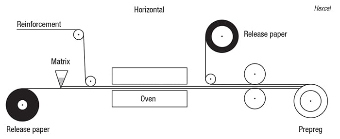
Due to their considerable diversity, there are several widely used preparation methods for industrial composites. Hexcel’s Wind Energy team explains one such method, wherein industrial composites are produced on horizontal (diagram) or vertical impregnation lines. A thermosetting, hot-melting epoxy resin is blended and filled into a resin bath, which is used for casting a film on silicone-coated release paper. The weight of the resin film is adjusted by the gap between the resin bath and the release paper, allowing for precise control of resin distribution and weight, and thus precise control of final composite weight. The reinforcement material (glass, carbon or aramide) is added onto the epoxy resin film, and the assembly is subsequently pulled through a heated impregnation zone, where the reinforcement material is impregnated by the resin, ensuring that no dry fiber is left. At this point, the release paper is removed, and the impregnated fabric (also called prepreg) is wound onto a core with a thermoplastic polyfilm interleaf.
In late 2015, Covestro AG (Leverkusen, Germany; www.covestro.com) announced a milestone in the development of composite materials for wind turbines — the introduction of polyurethane, rather than epoxy, into the composite. “In the past, polyurethane has not been used for making composite parts using the vacuum infusion process,” says Kim Klausen, head of Covestro’s global wind projects. “Epoxy is the most widely used type of resin for this process. Today, 80% of all vacuum-infusion parts are made using epoxy.” Vacuum infusion is a widely used process for constructing turbine blades, in which glass fabric is set up between two vacuum foils. At one end of the foils, a liquid resin is introduced, and a vacuum is applied at the other end. However, polyurethane resins have a much lower viscosity than epoxies, which allows for faster infusion and better wetting of fibers, explains Klausen. The polyurethane-based parts are also said to produce less heat during the curing process and experience low shrinkage, which results in accurate parts and decreased risk of fiber buckling.
Covestro has collaborated with Saertex GmbH & Co. KG (Saerbeck, Germany; www.saertex.com) to determine the best type of glass to use with the resin. The non-crimp glass fabric used for the material imbues stability and strength, while helping to lower the weight of the overall blade. For the vacuum-infusion process, Covestro is employing a process from Hübers Verfahrenstechnik Maschinenbau GmbH (Bocholt, Germany; www.huebers.de) that allows for controlled mold filling through automatic adjustments to the output based on the infusion pressure. Within this cooperation, Hübers has also developed a machine that can effectively degas both components of the polyurethane resin (isocyanate and polyol), and also dry the polyol, in a continuous process. Figure 2 illustrates the process for infusing polyurethane resins.
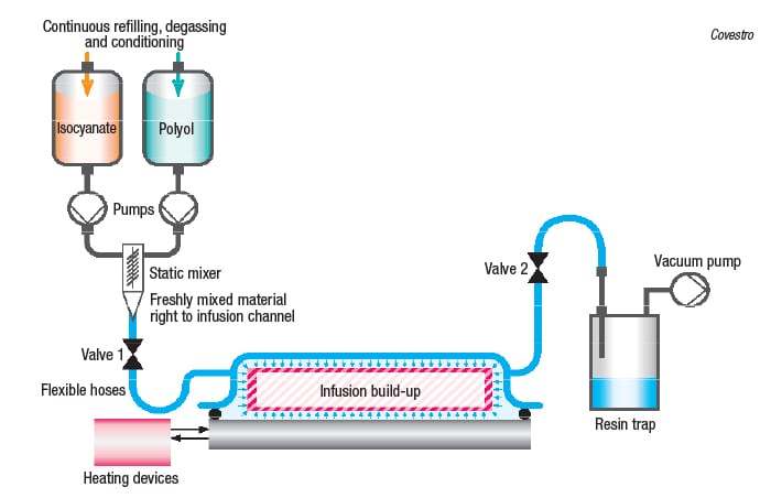
FIGURE 2. This process infuses polyurethane resins throughout a glass-fiber matrix to form
rotor-blade parts
The groups are continuing to optimize the process and material properties so that larger parts can be made. Covestro has produced parts made from the polyurethane-based composites that are as large as 25 m2. They have also demonstrated a wide range of thicknesses; as small as a few millimeters thick with just two layers of glass all the way up to 90-mm-thick parts that contain 120 layers of glass. A recent milestone was the manufacture of a 45-m spar cap (Figure 3), which is the portion of the turbine structure that must bear the full force of the wind. “The next step is to make a full blade,” says Klausen.
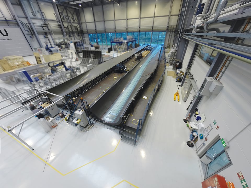
Covestro FIGURE 3. Polyurethane-based composites have been used to create large components for wind-turbine blades, including a 45-m spar cap
Protecting against the elements
Regardless of ambient conditions, wind turbines must continue to operate efficiently whenever the wind is blowing. This can require some unique design considerations. Researchers at Rice University (Houston; www.rice.edu) have developed a composite material consisting of an epoxy filled with graphene nanoribbons (GNRs) that acts as an effective de-icer for aircraft, wind turbines and other outdoor surfaces. The material can be applied as a thin surface coating or incorporated into a structure, depending on the application. The GNRs provide conductivity to the composite, so that when a small amount of voltage is applied, Joule heating occurs, melting any ice on the surface. In the case of wind turbines, a self-contained system can be configured, explains James Tour, professor of materials science and nanoengineering at Rice. A small amount of the power generated by the turbine itself can actually be directly drawn to the coating to provide the required heating when a built-in thermocouple indicates the potential formation of ice, activating the epoxy-GNR composite. Additionally, the rotating motion of the blades aids in the removal of melted ice.
Currently, the team has demonstrated the assembly of GNRs in the epoxy at laboratory scale, but the availability of raw materials makes commercial-scale production of this composite feasible. The epoxy is a standard two-part epoxy, and GNRs are commercially synthesized by Merck EMD (Darmstadt, Germany, www.emdgroup.com), according to a procedure developed at Rice University. The GNR composites are also quite versatile, explains Tour, as they can be made super-hydrophobic, transparent for use on glass surfaces, or can even provide a layer of electromagnetic shielding. The composite’s versatility and stability over a wide temperature range (GNRs are stable up to 1,000ºF) allow for a multitude of potential applications, including blending with ceramics.
Flying high with ceramics
In addition to the strength and stability required by composites in harsh environments, new composite combinations can also create materials that are more lightweight than traditional metals and alloys — an especially important quality for aerospace applications. This is where the integration of ceramics can become extremely beneficial. Ceramics impart strength into composites, while remaining lightweight and resistant to high temperatures. A category of composites known as ceramic-matrix composites (CMCs) is gaining ground in many sectors, due to their extremely desirable suite of properties. CMCs usually consist of a ceramic matrix reinforced with a network of ceramic fibers. GE Aviation (Evendale, Ohio; www.geaviation.com) is one of the first companies to manufacture CMCs commercially, and last October announced plans to construct two adjacent CMC production facilities in Huntsville, Ala.The two plants will work in tandem — one producing silicon carbide (SiC) ceramic fibers, and the other applying proprietary coatings to the fibers and forming them into a matrix to produce what is known as CMC tape. The CMC tape will then be sent to another GE site in Asheville, N.C., which is currently the only site in the world where CMC components are mass produced, according to GE.
Until the Huntsville plants start up in 2018, the Asheville site, which opened in late 2014, will continue to receive raw materials from NGS Advanced Fibers Co. (NGS), a company in Japan jointly owned by Nippon Carbon, Herakles Safran France and GE. According to GE, the Huntsville plants will be the first in the U.S. to mass-produce SiC fibers, and more CMC tape will be made there than anywhere else in the world. NGS is also currently constructing a new factory for SiC fibers in Japan to meet global demand, which GE projects will grow tenfold by 2020.
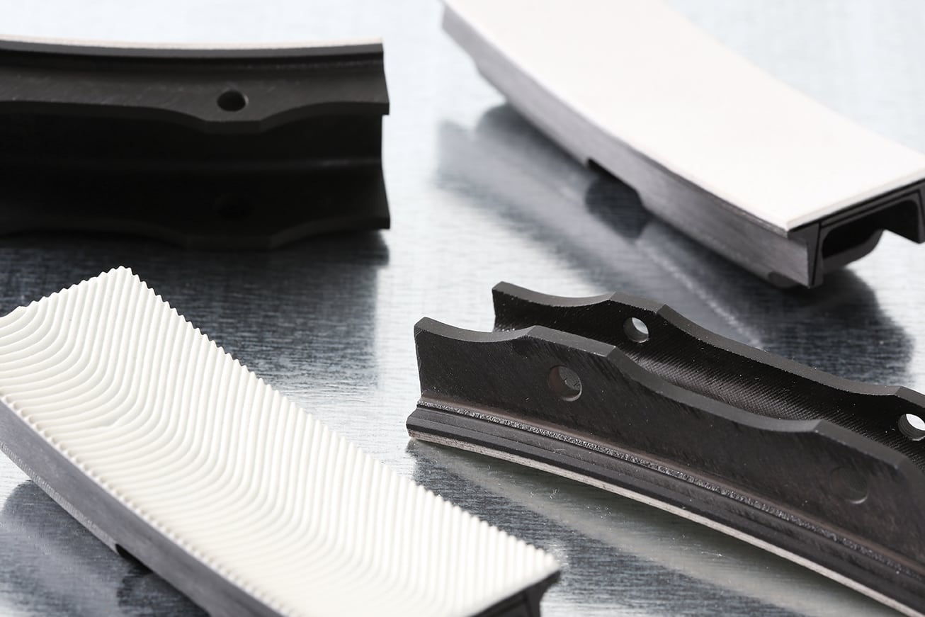
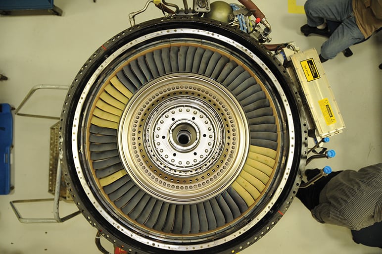
In the past, CMCs were difficult to produce at a large scale and were only able to be used in large structures — the ability to produce smaller, more complex components is a breakthrough. At present, the main end-use for GE’s CMCs is to replace metal composites in components for the company’s LEAP jet engines, specifically high-pressure turbine shrouds (Figure 4).
GE Aviation
FIGURE 4. High-pressure turbine shrouds constructed of ceramic matrix composites (CMCs) are resistant to the extreme temperatures experienced in jet engines
When compared to other materials used in jet-engine components, CMCs are more lightweight (reportedly one-third the density of metal alloys) and resist higher temperatures, leading to better fuel efficiency. The CMCs are said to operate at temperatures as high as 2,400ºF, which is 500ºF hotter than superalloys can handle. “Withstanding higher temperatures means we can push more air through the engine instead of diverting some to cool off metal parts and keep them from melting,” explains a representative from GE Aviation. “CMCs are also stronger than some metal parts and will last longer, resulting in less time and money spent on maintenance, repair and overhaul.” GE Aviation has also demonstrated the use of rotating CMC components in a low-pressure turbine (Figure 5), said to be an industry first. GE emphasizes that the applications for CMCs go beyond jet engines — the company’s Power and Water business has tested CMCs in air-cooled gas turbines and also used prototype CMC parts to replace superalloys in large gas turbines.
GE Aviation
FIGURE 5. These low-pressure turbine blades are said to be the first-ever use of CMCs in rotating parts in an engine
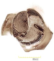
Beyond CMCs, SiC is an important part of other composites. A new metal nanocomposite developed by researchers from the University of California, Los Angeles (UCLA; www.ucla.edu) has garnered a great deal of attention due to its very high strength, lightweight structure and mechanical stability at temperatures up to 400ºC. Composed of a magnesium-zinc alloy infused with SiC ceramic nanoparticles, the key to this material’s unique properties is the ability to uniformly disperse the dense SiC nanoparticles throughout the magnesium (Figure 6) — a task that has not been achievable at this scale until now. The attractive forces between nanoparticles tend to form clusters within the metal matrix, but UCLA’s method leverages the small van der Waals attractions between the particles and the molten metal and high thermal-motion energy to stabilize the dispersion.

UCLA
FIGURE 6. Uniform distribution of dispersed nanoparticles in a magnesium matrix gives this material unique qualities
The research team, led by Xiaochun Li, Raytheon Chair in Manufacturing and professor of materials science and engineering at UCLA, injected the SiC nanoparticles into a molten bath of the magnesium alloy, and incrementally concentrated the nanoparticles in the mixture by partially evaporating the molten metal in a vacuum furnace. Once solidified, the resulting composite contained 14 vol.% SiC, and after mechanical processing, it boasted a record-high yield strength of 710 MPa for magnesium alloys. “In our lab, samples of a few grams of magnesium were used. But the process is solidification-based and would be scaled up without much difficulty,” says Li. Potential applications for the new metal are wide-ranging, spanning the automotive, aerospace, medical and electronics industries. In fact, according to Li, industrial interest in the technology has been significant, with over 30 companies inquiring about commercialization for various applications. When compared to other crystallized metals, this material’s high specific strength and specific modulus — said to be the highest ever reported for a polycrystalline metal — make it especially useful for energy-efficient applications, explains Li.
Going a step further, the team has also considered the recyclability of the material, citing the ease of recycling magnesium compared with other materials, such as polymers, as a key benefit. “The recycling of magnesium is very easy, since magnesium can be evaporated by a low-vacuum mechanical pump and then condensed to a cold plate. The magnesium nanocomposites can be recycled by this technique too, as evaporation can be used to recycle magnesium while the nanoparticles will be left behind for collection and cleaning,” says Li.
Boosting materials via 3-D printing
HRL Laboratories FIGURE 8. Additively manufacturing parts from ceramic-based materials has been demonstrated at bench scale
While ceramics boast many attractive qualities for a variety of applications, there are some limitations, due to their extremely high melting point and brittle structure. Ceramics are notoriously difficult to machine, and conventional processing techniques can inhibit the strength and versatility of end products. Researchers at HRL Laboratories, LLC (Malibu, Calif.; www.hrl.com) have overcome these restrictions by formulating a resin system based on a polymer-derived ceramic that is compatible with additive manufacturing processes, also known as three-dimensional (3-D) printing. This approach extends the potential for parts of nearly any shape or size to be constructed from ceramics. For more information on 3-D printing, please see 3-D Printing Accelerates, Creating CPI Opportunities, Chem. Eng., Feb. 2015, pp. 20–23.
The silicon oxycarbide-based ceramic was attractive for 3-D printing, says Zak Eckel, HRL senior development engineer, because the polymer’s silicon backbone has the ability to carry ultraviolet-active functional groups, which lends itself to the additive manufacturing process. The resin’s potential was first demonstrated in a self-propagating photopolymer wave-guided process, and researchers decided to test its feasibility for additive manufacturing. A major advantage of using this resin for additive manufacturing is that traditional firing processes can be used (Figure 7), with no additional processing steps, says Eckel. The 3-D printed part is simply pyrolized in an inert atmosphere at temperatures up to 1,000ºC, converting the resin into a fully dense, non-volatile ceramic. The research team has manufactured several parts at benchtop scale (Figure 8), and plans to scale up production to make even larger parts of increasing complexity. A hurdle in scaleup, according to Eckel, will be to ensure that the material is adaptable and consistent with different 3-D printing equipment and techniques.
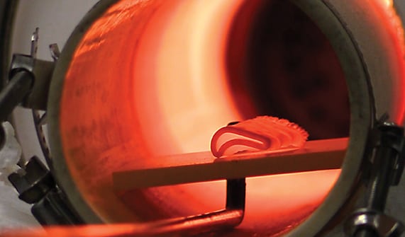
HRL Laboratories
FIGURE 7. Following 3-D printing, ceramic-composite parts are sent into a conventional firing process
The team is also investigating other polymer backbone materials besides silicon for additional 3-D-printable ceramic resins, allowing for a wider range of final product properties. There is even potential for the resin and resulting parts to be integrated into CMCs, says Eckel. Although present research is focused on manufacturing ceramic parts for the aerospace and automotive industries, the material’s versatility lends itself to numerous applications, including catalyst supports and high-temperature-resistant burners.
Oak Ridge National Laboratories (ORNL; Oak Ridge, Tenn.; www.ornl.gov), in collaboration with Cincinnati Inc. (Harrison, Ohio; www.e-ci.com), has also developed a system for integrating composites into additive manufacturing processes. The project, dubbed BAAM-CI, is said to be the first process that can deposit carbon-fiber-reinforced plastic composites into printed materials, making the resulting parts stronger and stiffer. The additive manufacturing process for these parts is also more efficient than other production methods involving composites, such as stamping and blow molding, says ORNL.
Composite maintenance
As materials become more advanced and end-product lifetimes continue to increase, composite maintenance and repair is another significant area for development. Researchers at Sandia National Laboratory (Albuquerque, N.M.; www.sandia.gov) are investigating non-destructive testing methods for composites, including techniques based on sonograms, infrared imaging, ultrasonic spectroscopy, flashed thermography and more. These methods are being evaluated for accuracy and applicability for detecting fractures and deformities in composites during various stages of processing. Non-destructive testing is particularly valuable for composites, since the outside surface may not reflect the condition inside the material. Citing the decades-long lifecycle required for many composite parts, the research team is currently writing inspection procedures based on their new testing methods.
Going forward, such inspection techniques, along with methods for composite repair and recycling, will certainly continue to be crucial to ensuring that composite parts in demanding applications like aerospace and wind power live up to their full potential.