The relationship between valve selection and safety certification still causes confusion. A focus on functional safety can help to elucidate
Among the many varied viewpoints on the topic of emergency shutdown (ESD) valves, there are several aspects that continue to spark discussion and cause confusion due to a lack of complete clarity, including the relationship between valve selection and safety certification. In this article, we aim to clarify a few of the most misunderstood points associated with the selection of ESD valves. And in doing so, we hope to bring greater recognition to the concept of functional safety, which is associated with the safety integrity level (SIL) standards laid out by the International Electrotechnical Commission (IEC; Geneva, Switzerland; www.iec.ch):
- IEC 61508 (Functional Safety of Electrical/Electronic/Programmable Electronic Safety-Related Systems)
- IEC 61511 (Functional safety – Safety instrumented systems for the process industry sector)
Functional safety is a much broader set of concerns than the question of which valves to select.
Certification has been a key issue of confusion recently: many people think “a SIL 3 certificate for valves is a must; likewise for a solenoid valve.” Still, certification is just one part of ESD valve selection. Certification is not mandatory according to IEC 61508 and 61511, but it can bring valuable information when a manufacturer’s design or design process is being evaluated by a third party (Figure 1). Additionally, certification ensures that a product is compliant with a standard.
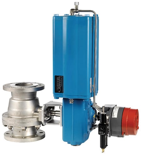
Figure 1. Certification of ESD valves ensures that products are compliant with standards, but does not guarantee valve performance
However, certification does not, by itself, guarantee anything about valve performance. A new certificate does not make the valve or valve unit suitable for the safety loop. Valve selection is still the most critical aspect. The same steps regarding valve suitability for the process must be considered in the ESD service as with any other valve. So, included in this article are valuable steps to take for ESD valve selection to make sure the whole picture is taken into consideration.
Valve selection
Ideas, opinions and experiences abound regarding which type of valve to use in a specific service. Some of these opinions can bring valuable field-proven information; others may be simply based on the wrong conclusions.
A good example of this situation comes from a conversation the author had a few years ago with several experienced plant personnel who were absolutely confident that ball valves are not suitable for gas processes. This assertion was based on observations of real valve performance from years before, when an incorrect material selection led to a situation in which the valve was performing poorly and was finally destroyed. The plant personnel concluded that the valve failed because it was the wrong type (ball valve). Yet in similar processes across the globe, there are thousands of ball valves doing a very good job. Therefore, the valve’s problems were based on the fact that its materials of construction were not suitable for the application — any type of valve made from incorrect materials would have led to a failure in this situation.
Failures can be divided into two categories: systematic failures and random failures. When selecting valves, it is imperative to make sure that the valve chosen is capable of performing in the intended service. If a valve repeatedly fails in the same manner, it is likely a systematic failure and cannot be avoided. In this case, improving the valve’s performance will occur only by changing something in the selected components of the valve.
In ESD valve selection, the safety loop must be free of systematic errors. This requirement concerns not only the valve body, but also other valve components. For example, the actuator must be capable of achieving sufficient torque or force to operate the valve. And the intelligent safety solenoid must have the capacity to reach the required shut-off or opening time of the unit, which is specified in safety requirements.
As an example of a systematic error, we can use the material selection mistake in chloride service. With dry chlorine, even carbon steel is a suitable valve body material. However, when enough moisture is present, hydrochloric acid forms, and the carbon steel body is no longer a suitable material. To avoid systematic failures, the body material needs to be enhanced to a grade that can withstand the more aggressive flow media. In this example, the root cause of the failure is the selection of an unsuitable material selection. In such a situation, the same failure will occur regardless of the type of valve chosen.
The key to avoiding such systematic failures is the use of application-based valve selection.
Functional safety
In recent years, awareness of functional safety within the chemical process industries (CPI) has been increasing. Having a greater number of people aware of the IEC standards and the ideas behind them is a positive development. Still, there is a lot of confusion around the standards, as well as the requirements for valves and how to comply with these requirements. A commonly held belief is that the simplest solution is just to ask for a SIL certificate and all will be fine.
However, the SIL certificate alone is not enough. The certificate usually describes what the final element is, such as a valve, and for which SIL that valve is suitable. SIL-3 certification does not necessarily mean that the final element fulfills SIL-3 requirements. It does mean that the valve is capable of working in a SIL-3 loop, but there are more points to be considered.
First is the SIL capability, which the certificate can confirm. Second is the hardware’s fault tolerance (HFT) to that particular SIL. In the certification, there is typically a different approach based on the various parties who have granted the certificate. Usually, certificates speak only to SIL capability, such as a valve being “SIL 3 capable.” Some certificates have an extra note that includes fault tolerance. For example, a valve could be be “SIL 3 capable in an HFT 1 (hardware fault tolerance) configuration,” which means there must be two valves in a “one out of two” (1oo2; duplex) configuration to satisfy the SIL 3 requirement. Or, there can simply be the text “SIL 3” without any further comments. The text “1oo2” means that one final element, like a valve, can fail and the safety function is still available.
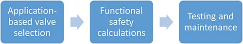
Figure 2. The key to avoiding systematic valve failures is application-based valve selection, which is supported by functional safety calculations and regular testing and maintenance
HFT is an important aspect in the IEC standards, and is usually the first topic that causes controversy. With study of IEC 61508, we can follow the safety fail fraction (SFF) method for defining HFT. For a valve, this means if the SFF is more than 90%, we can use one valve to satisfy the HFT of the SIL 3 requirement.
The calculation in Equation (1) is quite simple if the required values are available. Usually, these lambda values can be found from the valve manufacturer’s certificate. If not, then usually generic values can be used based on similar components.
SFF = (λ dd + λ S) / (λDd + λ Du + λ S) (1)
Where λ dd is the detected dangerous failure rate; λ S is the safe failure rate; and λDu is the undetected dangerous failure reate. The discussion about SFF is typically related to the valve part, because the SFF method is suitable for mechanical components like valves, and if the ratio of safe failures to all failures justifies the hardware fault tolerance.
Currently, it is more common to follow IEC 61511 and use the “table method,” in which the HFT is selected based on the predefined table by a different operating mode. Final elements, such as valves, are typically, but not always, in low-demand service. Therefore, the HFT for SIL 3 becomes the minimum of two valves in a 1oo2 setup. The minimum HFT for SIL 1 and 2 is one final element.
The HFT is not the only requirement that needs to be considered. The probability of failure on demand average (PFDavg) also must be calculated for the setup. If the PFDavg does not satisfy the needed safety integrity level demand, a few options exist. The easiest is to double the components. For example, SIL 2 could be satisfied with one valve, but if the PFDavg is low and refers to SIL 1, we do not have a capable final element configuration.
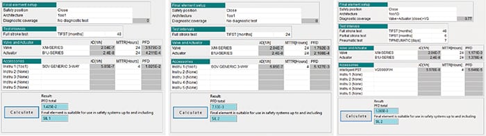
Figure 3. The average probability of failure on demand (PFDavg) must satify the required safety integrity level (SIL) demand. Periodic testing intervals like those shown here are the backbone of testing
Figure 3 presents a few options to satisfy the PFD requirement. Figure 3 (left) shows the base level with a 48-month testing interval. Figure 3 (middle) shows the same components, but the testing interval is shorter. Instead of 48 months, there is a 24-month testing interval and in this case, there is a significant change in the PFD value.
Sometimes, it is not that easy to change the testing interval to a proof test, because it will have an impact on the plant operation. Therefore, in Figure 3 (right), the solenoid valve has been replaced with an intelligent safety solenoid and partial-stroke testing has been utilized to increase the amount of testing, while keeping the proof test interval at the same length (48 months). This will increase the testing flexibility.
ESD valve maintenance
Very often, ESD valves are considered to be “install and forget” valves. However, although they do not control the process all the time and are mostly in a normal state, ESD valves must be considered to be on duty at all times. A valve that has been in a pipeline for several years without any operation, testing or maintenance might not work when it is needed. Therefore, testing and maintenance are a vital part of an ESD valve life.
The first point to consider here is the periodic testing intervals from the PFD avg calculations. These intervals are the backbone of testing and are a minimum requirement to keep the valve in duty. Some services are more severe than others, and in PFD avg calculations, this is not always noticed and addressed. Partial-stroke testing can be a great help to check the valve condition while the valve is in operation. But to keep the needed and defined SIL, a proof test must also be made.
The testing interval is important in both calculations and in a real process. Equation (2), from the International Society for Automation (ISA; Research Triangle Park, N.C.; www.isa.org) standard TR-96.05.01, shows the following:
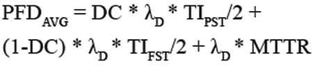 (2)
(2)
DC = diagnostic coverage
λd = Dangerous failure rate
TIPST = Partial stroke test interval
TIFST = Full stroke test interval
MTTR = Mean time to restore
Testing is needed to keep the required safety integrity level.
From the graph in Figure 4, the green line represents the PFD value, which when increasing, results in a decreasing SIL level at a certain period of time. If the requirement is SIL 2, as in this example, the limit is reached in just over three years. But a problem occurs, for example, if the plant shutdown period is four years. The other line in Figure 4 marked with blue color is the PFD value with partial-stroke testing. The PFD value increases, but at a lower pace. Eventually, we will reach the limit of the required SIL and cannot avoid the full stroke and proof test, but the advantage is now that the testing period for full testing can be more flexible.
It is important to remember that proof testing cannot be avoided by conducting the partial-stroke test alone, but the testing interval can be changed. The example calculations in Figure 3 include 77% diagnostic coverage.
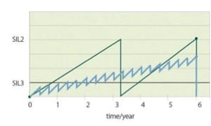
FIGURE 4. The green line represents the PFD value, which when increasing, results in a decreasing SIL level at a certain period of time
Concluding remarks
It is promising that the awareness of functional safety has increased during the past few years. At the same time, however, more confusion around this topic has arisen. In this article, we outline a few of the main steps when it comes to valves and functional safety. Even though SIL and PFD calculations are a hot topic at the moment, we must still remember that the most important aspect is application-based valve selection. After we have done a good job in selecting the valve and other components, we can then take advantage of the PFD calculations. It is important not forget to maintain ESD valves. This is vital to keep the required SIL and ensure that the valve works in the process when needed to carry out its safety function.
Edited by Scott Jenkins
Author
 Ville Kähkönen is the director of industry management at Metso Flow Control Inc. (Töölönlahdenkatu 2, FI-00100, Helsinki, Finland; Phone: +358 20 484 100; Email: [email protected]). He has over ten years of experience in different roles, including business management, research and development, engineering and marketing. He has been with Metso more than 10 years. Kähkönen holds a master’s degree in materials science and industrial management from Helsinki University of Technology and has studied at the Helsinki School of Economics.