When hoppers are designed without consideration of the actual materials being handled, problems inevitably arise. Follow this guidance to avoid common solids-handling issues, such as erratic flow and no flow
Pivotal work on the development of the theory of bulk solids flow began in earnest in the early 1950s, when Andrew Jenike applied a solids-mechanics-continuum concept to develop a logical, theoretical approach for understanding and managing solids flow. He developed testing methods, equipment, and design techniques and conducted experiments to confirm and refine his groundbreaking analysis [1].
Prior to Jenike’s work, bins and hoppers were typically designed primarily from an architectural or fabrication standpoint (for instance, hopper walls were sloped 30 deg from vertical to reduce the waste of wall materials, or 45 deg to minimize headroom requirements and simplify design calculations). However, extensive experience has shown that designing equipment without regard to the actual bulk materials being handled often leads to flow problems, such as arching, ratholing, erratic flow and even no flow. By measuring the flow properties of a bulk solid, the flow behavior of the material can be predicted, and more reliable hoppers and bins can then be designed.
Competing flow patterns
Two primary flow patterns can occur in a bin or a silo: mass flow and funnel flow (Figure 1). In mass flow, the entire bed of solids is in motion when material is discharged from the outlet. This behavior eliminates the formation of stagnant regions in the vessel, and affords a “first-in, first-out” flow sequence, which provides a more uniform velocity profile during operation. A uniform velocity profile also helps to reduce the effects of sifting segregation.
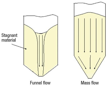
FIGURE 1. Two types of flow patterns can occur when a bulk solid is discharged from a hopper, bin or silo: A typical funnel flow pattern is shown on the left, and a mass flow pattern is shown on the right
By contrast, in funnel flow, an active flow channel forms above the outlet, but stagnant material remains (called ratholes) at the periphery of the vessel. Funnel flow can cause erratic flow, exacerbate segregation, reduce the live capacity of a vessel, allow particle degradation (leading to caking and spoilage) in stagnant regions. Depending on the vessel size, funnel flow can also induce high loads on the structure and downstream equipment, due to collapsing ratholes and the formation of eccentric flow channels.
For many materials, flow problems can be eliminated by ensuring that a mass flow pattern exists in the vessel. The first step to achieving mass flow is to ensure that the converging walls are steep enough, and have friction low enough, to allow the bulk materials to slide along them. This is accomplished by first testing the material to measure wall friction, and then calculating the minimum hopper angle that will allow mass flow.
Hopper angle for mass flow
Once the wall friction results are known, the recommended hopper angle to ensure mass flow can be readily calculated. The angle of wall friction (φ’) is obtained by following the method described in ASTM D-6128 [2]. The test is performed using an instrument (shown in Figure 2) that involves placing a sample of powder inside a retaining ring on a flat coupon of wall material. Various normal loads are then applied to the powder, and the powder inside the ring is forced to slide along the stationary wall material. The resulting shear stress is measured as a function of the applied normal stress.
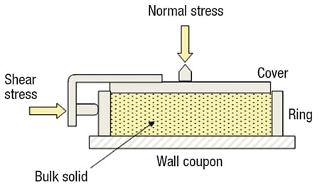
FIGURE 2. By measuring the force required to slide a sample of powder along a wall coupon, the angle of wall friction can be determined
After a number of values have been recorded, the wall yield locus is identified by plotting shear stress against normal stress (Figure 3). The angle of wall friction (φ’) is the angle that is formed when a line is drawn from the origin of that graph to a point on the wall yield locus.
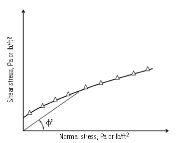
FIGURE 3. The angle of wall friction (φ’) is determined by drawing a line between the wall yield locus (which is constructed by plotting shear stress against normal stress), and the origin, as shown here
δ
φ
Jenike [1] found that the hopper angle required to allow flow along the walls depends on the friction between the powder and the walls, the friction between powder particles, and the geometry of the hopper. Design charts originally developed by Jenike [1] provide allowable hopper angles for mass flow, given values of the wall friction angle and the effective angle of internal friction (which is determined by shear cell testing).
The charts mentioned above [1] are summarized in Figures 4 and 5 for conical and planar hoppers (for example, wedge-shaped hoppers and transition hoppers), respectively. Note that the outlet of a wedge-shaped hopper must have a length that is at least three times its width for the relationship shown in Figure 5 to apply.
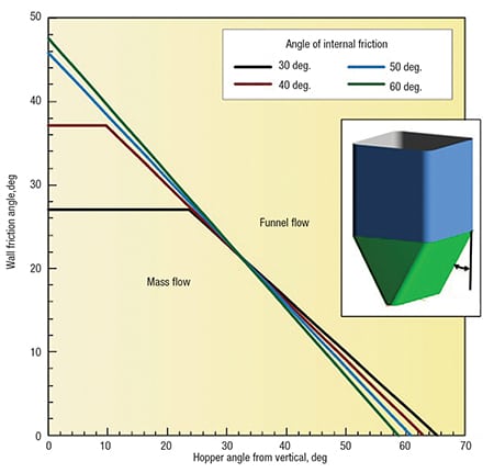
FIGURE 5. This plot shows the recommended wall angles to ensure mass flow in a hopper with flat walls and a slotted outlet
Values of the allowable hopper angle θ’ (measured from vertical) are on the x -axis, and values of the wall friction angle φ’ are on the y -axis. Any combination of φ’ and θ’ that falls within the limiting mass flow region of the chart will provide mass flow.
Hoppers with round or square outlets should not be designed at the theoretical mass-flow hopper-angle value. Otherwise, a small change in powder properties may cause the flow pattern inside the hopper to change from mass flow to funnel flow — bringing its associated risk of flow problems. A 3-deg margin of safety (with respect to the mass-flow hopper angle given in Figure 4) is recommended.
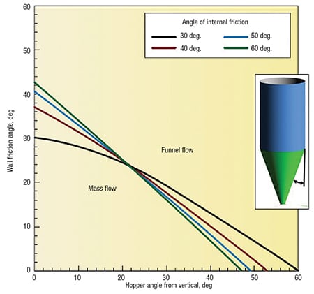
FIGURE 4. This plot shows the theoretical mass-flow hopper angles for hoppers with round or square outlets. Note: a minimum safety factor of 3 deg should be used
Sloping walls required for mass flow in wedge-shaped hoppers can be 10–12-deg less steep than those required to ensure mass flow in conical hoppers. Wedge-shaped and transition hoppers are therefore frequently used for materials that have high wall friction.

Minimum outlet dimension
The outlet of the hopper section must be large enough to prevent cohesive arches or stable ratholes from developing. The required outlet size depends on the cohesive strength and the bulk density of the powder. The cohesive strength is measured by shear-cell testing, as described in ASTM D-1628 [2] and D-6773 [3].
Figure 6 shows schematic diagrams for two common shear-cell testers. A sample of powder is placed in a cell and then pre-sheared — that is, the sample is consolidated by exerting a normal stress, and then sheared until the measured shear stress is steady. (This is shown in Figure 7, by the point (σss, τss)).
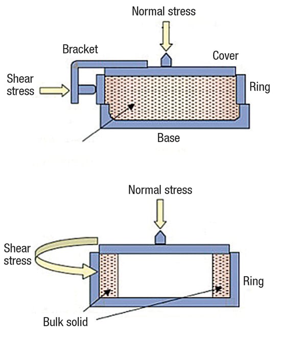
FIGURE 6. Two versions of the shear cell tester — the direct shear cell tester (top) and the ring shear cell tester (bottom) — are used to measure the cohesive strength of bulk solids
Next, the shear step is conducted. During this step, the vertical compacting load is replaced with a smaller load, and the sample is again sheared until it fails. These pre-shear and shear steps are repeated at the same consolidation level for a number of reduced normal stresses, and the yield locus is then determined by plotting the failure shear stress against the normal stress (Figure 7).
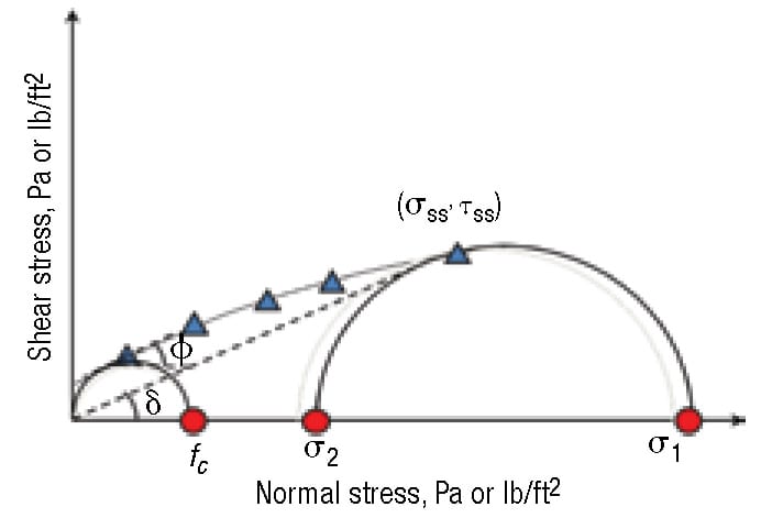
FIGURE 7. A Mohr’s circle drawn through the steady-state point and tangent to the yield locus gives the major consolidation stress. A Mohr’s circle tangent to the yield locus that passes through the origin gives the cohesive strength
From the yield locus, the major consolidation stress (σ1) and the cohesive strength ( f c) are determined. Because bulk solids are anisotropic, the stress on the sample varies with direction. The maximum value of the stress, which is called the major consolidation stress, depends on the material’s internal friction and the magnitudes of the normal and shear stresses imparted on the sample during the test.
Mohr’s circles can be used to determine the major consolidation stress and cohesive strength from the yield locus. The major consolidation stress is the value of the intersection of the horizontal axis and a Mohr’s circle, drawn through the steady-state point and tangent to the yield locus. The cohesive strength is related to the state of stress where a free boundary exists. Hence, the cohesive strength is the intersection of the horizontal axis and a Mohr’s circle that passes through the origin (where stress equals zero) and is tangent to the yield locus. The kinematic angle of internal friction (φ) and effective angle of internal friction (δ) can also be determined, as shown in Figure 7.
By conducting the test over a range of consolidation states, the relationship between consolidation pressure and the cohesive strength of the bulk material can be established, following a procedure established and described by Jenike [1]. This relationship is commonly called the material’s Flow Function. An example of a powder’s Flow Function is given in Figure 8.
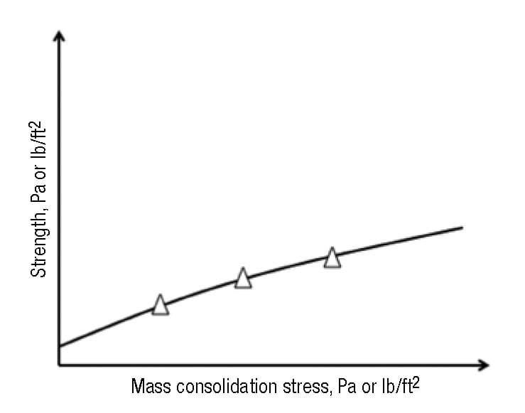
FIGURE 8. The relationship between the major consolidation stress and the cohesive strength is called the Flow Function
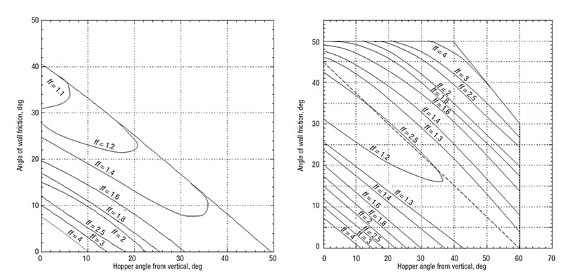
left – FIGURE 9a. The flow factor (ff) is the ratio of the arch stress to the major consolidation stress and depends on the effective angle of internal friction, the hopper geometry, the hopper angle, and the wall friction angle. The above diagram gives flow factors for conical hoppers, δ = 50 deg
right – FIGURE 9b. The diagram shown here gives flow factors for hoppers with flat walls and slotted outlets, δ = 50 deg
Once a material’s Flow Function has been determined, the minimum outlet width or diameter that will prevent cohesive arching can be calculated, using the hopper’s flow factor (ff). Jenike defined the flow factor using Equation (1):
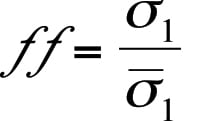
(1)
The flow factor is a function of the powder’s effective angle of internal friction, the hopper angle, and the wall friction angle. Charts that provide flow factors for conical and wedge-shaped hoppers are given in Jenike [1]; Examples are shown in Figures 9a and 9b. Typical values of the flow factor range between 1.1 and 1.7.
Superimposing the material’s Flow Function and flow factor on the same graph allows the cohesive strength and arch stress to be compared. The flow factor is constructed by drawing a line having a slope equal to 1/ff through the origin.
There are three possibilities:
- The Flow Function lies below the flow factor, and the two curves do not intersect. When this is the case, the stress imparted on the arch is always greater than the material’s cohesive strength, and there is no minimum outlet dimension requirement to prevent cohesive arching
- The Flow Function lies above the flow factor and the curves do not intersect. The bulk solid will not flow due to gravity alone, and another means of discharging the powder must be employed
- The Flow Function and flow factor intersect, as shown in Figure 10. At the point where the two lines intersect, the arch stress and the cohesive strength of the bulk solid are the same and equal to the critical stress (σcrit)
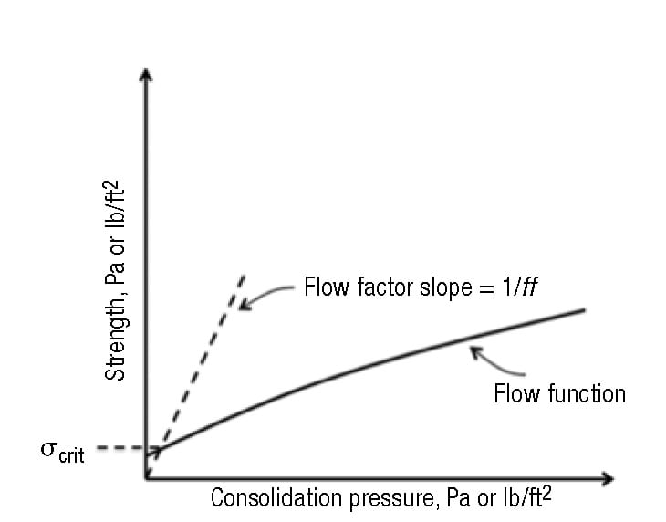
FIGURE 10. The critical stress σcrit is determined from the intersection of the Flow Function and flow factor. At the point where the two lines intersect, the arch stress and the cohesive strength of the bulk solid are the same, and equal to the critical stress
The minimum outlet diameter or width to prevent a cohesive arch from developing, Bmin, can then be calculated from Equation (2):
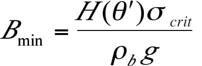
(2)
The function H (θ’) is shown in Figure 11. For funnel flow hoppers, the outlet must be large enough to prevent a cohesive arch and stable rathole from developing. To prevent the formation of a stable rathole, the hopper outlet diagonal should equal or exceed the critical rathole diameter, DF. The critical rathole diameter is calculated by first determining the major consolidating pressure, σ1, on the powder. In some cases, the consolidating load can be estimated by the Janssen equation (Equation (3)):
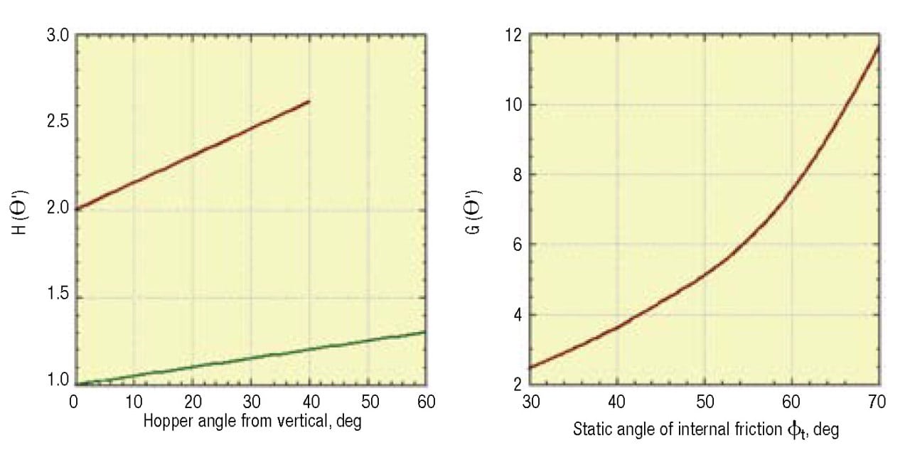
FIGURE 11. Functions H(θ’) and G(Φ). are used to determine outlet dimensions that prevent a cohesive arch or stable rathole from developing
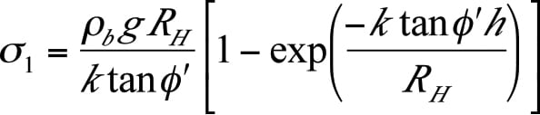
(3)
The critical rathole dimension is then calculated using Equation (4):
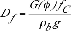
(4)
In Equation (4), f C is the cohesive strength of the powder at the calculated consolidation pressure.
For wedge-shaped and pyramidal hoppers, stable ratholes will not form if the diagonal of the outlet is equal to D F or greater. The diameter of the outlet of a conical funnel-flow hopper should not be less than the critical rathole dimension.
If a hopper with a circular outlet is designed with an opening large enough to prevent the development of a stable rathole, cohesive arching will not occur. For wedge-shaped hoppers, the width of the slotted outlet must be large enough to prevent a cohesive arch from developing. The same procedure that is used to determine the minimum outlet width to prevent arching in a wedge-shaped mass–flow hopper is followed, except that a flow factor of 1.7 is used.
Note that these analyses assume continuous handling of the powder. If the powder is to be stored at rest for a period of time, time tests should be conducted. Time tests are described in ASTM D-6128 and D-6773 [ 2, 3 ].
Feeder considerations
Feeders can also be a source of hopper flow problems if the incorrect devices are used or if they are improperly designed. This is especially true for hoppers with slotted outlets, where feeders should be designed to draw uniformly along the entire cross-section of the outlet in order for mass flow to occur. However, even hoppers with round outlets can have uneven flow if a proper interface is not utilized.
Rotary valves are often used beneath hoppers with round outlets. They are particularly useful for applications where a seal must be provided to prevent air from flowing out of or into the hopper outlet. If a rotary valve is used, a short vertical spool section should be installed between the hopper outlet and valve inlet. Otherwise, material may flow preferentially from the upside of the valve and affect the flow pattern inside the vessel. This is shown in Figure 12.
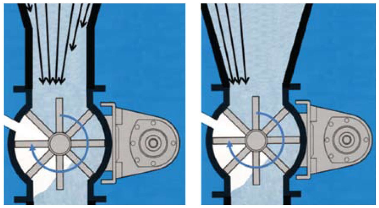
FIGURE 12. A hopper with a rotary valve should have a spool section above the valve inlet (left); otherwise, preferential flow may occur on one side of the hopper (right)
Screw feeders are primarily used to control the discharge of powders from hoppers with slotted outlets. A screw is comprised of a series of flights wound around one or more shafts. A screw that has a constant pitch and diameter (and a constant shaft diameter) will give rise to the formation of a flow channel at the back of the hopper over the first flight of the screw. As shown in Figure 13, this channel will draw material from the top surface into the flow channel until a stable rathole forms and the channel empties. The rathole will then periodically fail as the base of the material falls above the screw. This will continue to broaden the flow channel, and this cyclic fail-flow-empty cycle will continue until the hopper empties.
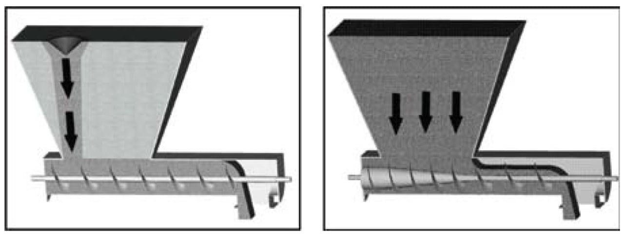
FIGURE 13. A screw feeder with a constant diameter and a constant pitch screw results in funnel flow. A mass-flow screw feeder where the screw has a tapered shaft and increasing pitch sections ensures that all material will flow when discharged
A mass flow screw feeder, comprised of a tapered section followed by a section with increasing pitch, ensures that the capacity of the feeder increases in the direction of flow (see Figure 13). The length of the cone and the pitch schedule are chosen such that the capacity of the screw increases linearly along the hopper length. The length of the screw must be between three and six times the width of the hopper to meet fabrication tolerances, and the screw diameter is equal to the hopper width.
Discharge rate
For coarse powders, the maximum discharge rate from a mass flow hopper can be calculated using Equation (5):
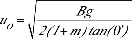
(5)
The parameter m is equal to 0 for slotted outlets, and is equal to 1 for round or square outlets. The mass discharge rate is equal to the product of the velocity, outlet cross-sectional area, and the material’s bulk density at the outlet.
The maximum flowrate of a fine powder can be several orders-of- magnitude lower than that of coarser materials, due to an adverse gas-pressure gradient that forms. Because of vacuum that naturally develops above a hopper outlet when the voids in fine powders expand as the material discharges, the resulting counter flow of gas will hinder the solids flow. A limiting condition occurs when the compaction in the cylinder section forces too much gas out through the material’s top surface.
At a critical solids-discharge rate, the solids-contact pressure drops to zero, and efforts to exceed this limiting discharge rate will result in erratic flow. Permeability testing is required to determine the outlet size required to achieve a desired discharge rate for fine powders. The limiting discharge rate from a mass-flow hopper for fine powders can be calculated using Equation (6):
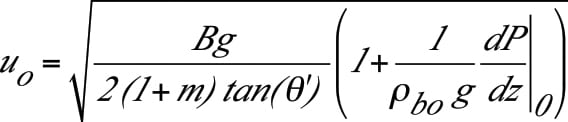
(6)
The magnitude of the pressure gradient depends on the bulk density and the permeability of the powder. Note that because of the vacuum that develops above the hopper outlet, the pressure gradient, dP/dz, is negative. See Schulze [4] for a discussion of the challenges of accurately predicting the pressure gradient.
Final remarks
Compared to liquids and gases, chemical engineers’ training in bulk-solids handling is often lacking. By understanding the fundamental principles and conducting proper flow properties tests, a chemical engineer can design reliable systems for storing and handling bulk solids. Knowing the relationship between a material’s cohesive strength and consolidation stress allows the engineer to calculate hopper-outlet dimensions that will prevent flow obstructions from developing. Similarly, wall-friction test results allow engineers to determine hopper geometries that are required to promote mass flow. Permeability tests are required to calculate limiting mass-flow discharge rates.
Edited by Suzanne Shelley
References
1. Jenike, A.W., Storage and Flow of Solids, Bulletin 123, University of Utah Engineering Station, 1964 (revised, 1976).
2. ASTM D-6128, Standard Test Method for Shear Testing of Bulk Solids Using the Jenike Shear Cell, ASTM International, 2006.
3. ASTM D-6773, Standard Shear Test Method for Bulk Solids Using the Schulze Ring Shear Tester, ASTM International, 2008.
4. Schulze, D., “Powders and Bulk Solids – Behavior, Characterization, Storage, and Flow,” Springer, New York, 2007.
Author
 Greg Mehos is a senior project engineer with Jenike & Johanson, Inc. (400 Business Park Dr., Tyngsboro, Mass.; Phone: 978-649-3300; Email: [email protected]), and an adjunct professor at the University of Rhode Island. Mehos has been involved in a wide range of bulk-solids handling projects, including designs of hoppers, dryers, gasifiers and moving-bed reactors, as well as analyses of purge and conditioning columns. He received his B.S. and Ph.D. in chemical engineering from the University of Colorado and an M.S.Ch.E. from the University of Delaware. He is a registered professional engineer in Colorado and Massachusetts and a member of AIChE. He served on the executive board of AIChE’s Particle Technology Forum and is a past chair of the Boston AIChE section.
 David S. Morgan is a senior consultant at Jenike & Johanson (3485 Empresa Dr., San Luis Obispo, CA 93401; Phone: 805-541-0901; Email: dmorgan@ jenike.com). He has more than 40 years experience as a consultant specializing in the storage and flow of granular bulk material. Morgan has published several technical papers, participated in various international conferences, and presented numerous short courses in the field of bulk solids flow. He holds a B.Sc. (Eng.) from the University of Natal, South Africa.