Alternative designs for pressure relief systems may offer investment cost savings
Pressure relief systems for the chemical process industries (CPI) are essential to prevent a process system, or any of its components, from being subjected to pressures that exceed the maximum allowable accumulated pressure, by emergency venting to a closed relief system. These relief systems are normally very conservatively designed. For large, new petroleum refineries with capacities around 300,000 barrels/day (bbl/d), this can result in costs of up to 1% of the total refinery capital investments (Capex). This article presents simple project alternatives to traditional closed relief systems [ 1 ], based on American Petroleum Institute (API) standards, that can present significant investment-cost reductions.
Background
Overpressurization of process units can occur due to several reasons as indicated in API-521 [ 2 ]. Some of those reasons are the following:
- General power failure
- Cooling water failure
- Instrument failure
- External fire
Normally, general power failure or utility failure results in the highest vapor load for a closed pressure-relief system, and is therefore used as the design case. Before sizing a closed relief system, it is advisable to reduce these very high vapor loads by the following:
- Use high-integrity protection systems (HIPS) as recommended in API-521, which can result in a significant reduction of the vapor flowrates to the flare.
- Realize dynamic-system load modeling. This analysis for a complete petroleum refinery is very complex and is not normally used, but it can also result in flowrate reductions.
After defining the minimum possible vapor flowrates that correspond to the overpressure relieving rates defined by the design case, the closed relief system may be sized.
Traditional closed systems
A closed pressure-relief system is designed to safely control overpressurization of process units during emergencies by relieving the vapors to the flare, which destroys hydrocarbons in a high-temperature flame. Figure 1 shows a typical closed relief system that collects vapors and liquids in process-unit headers and separates the liquid in process-unit knockout (KO) drums before sending the vapor phase to the main flare header, and finally to the flare unit for destruction.
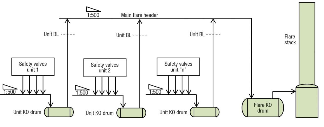
FIGURE 1. This sketch shows a simplified pressure-relief system for a petroleum refinery
In the traditional system, the unit KO drums and the flare KO drums are projected for the maximum vapor and liquid flowrates as determined from the analysis of the overpressure causes and indicated in API-521 [ 2 ]. The KO drums, process units and flare unit, are sized to separate particles in the range of 300–600 μm in diameter, and to hold liquid discharge for 20 to 30 minutes as per API-521 item 7.3.2.1.2 for these maximum flow conditions. The unit flare headers and the main flare header are also sized for these maximum flowrates. All the headers slope with a minimum inclination of 1:500 toward their respective KO drums, and are continuously purged using combustion gas or nitrogen from the upstream end toward the KO drums to avoid ingress of air into the system.
Optimized closed systems
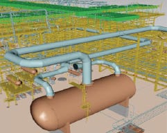
Figure 2. This large, horizontal process-unit KO drum requires the air coolers to be mounted very high
The calculation criteria for sizing the flare KO drums and process-unit KO drums result in very large vessels. This implies the need to install the collection headers very high above grade level, since they must drain to the KO drums. Equipment, such as air coolers that must be mounted above the process unit headers are consequently also very high. This requires long stretches of process piping to and from the equipment. Figure 2 shows such a situation. If it was possible to change the design criteria for the process-unit KO drums, the process-unit flare header and the air coolers may be installed at a lower level with considerably lower installation costs as a result of the use of less structural steel and process- and flare-header piping. At the flare unit, the KO drum is even larger than the process unit drums, and as a result, the main flare header at the inlet to the vessel is very high, as can be seen in Figure 3. Consequently, the main flare header at the flare-unit battery limits (BL) is also very high. Since the flare header in large, new, petroleum refineries is normally very long (about 2 km), it means that at the farthest point from the flare unit the header is at least 5 m higher than at the flare-unit battery limits. This installation requires a lot of structural steel to maintain the flare header at the required height, and consequently high investment costs for the pipe rack are required (Figure 4). The criteria used to size the KO drums for carryover of droplets that are 600 μm in diameter is, according to API-521, to eliminate the possibility of incomplete combustion with excessive smoking, possible “burning rain,” and even flame-out of the flare.
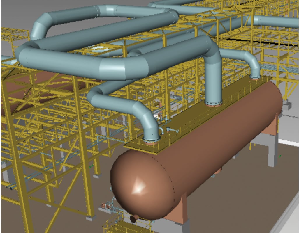
Figure 3. A large, horizontal flare-unit KO drum can require a very high piping arrangement
It is clear that the flare unit KO drum must be sized according to this limitation as it is upstream of the flare. However, this limitation is not necessary for the process unit vessels, as these are upstream of the flare-unit KO drum. In this case, if large droplets are carried over from the process-unit KO drums, the flare-unit KO drum will retain them and maintain adequate conditions for the flare. API-521 item 6.4.3.6.7 presents a clear explanation of the design parameters for these vessels: “ Some flare systems require a flare knockout drum to separate liquid from gas in the flare system and to hold the maximum amount of liquid that can be relieved during an emergency situation. “Knockout drums are typically located on the main flare line upstream of the flare stack or any liquid seal. If there are particular pieces of equipment or process units within a plant that release large amounts of liquid to the flare header, it is desirable to have knockout drums inside the battery limits to collect these liquids. This reduces the sizing requirements for the main flare knockout drum, as well as facilitates product recovery. “In general, a flare can handle small liquid droplets. However, a knockout drum is required to separate droplets larger than 300 μm to 600 μm in diameter in order to avoid burning liquid outside the normal flame envelope. If unit knockout drums are provided upstream of the main flare knockout facilities, these drums may be sized to separate droplets typically greater than 600 μm in diameter. The use of unit knockout drums effectively reduces the sizing requirement for the main flare knockout drum and facilities, See 7.3.2.1.
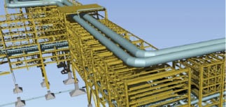
Figure 4. This sketch depicts a very high pipe rack to support the main flare header
“The liquid hold-up capacity of a flare knockout drum is based on consideration of the amount of liquid that can be released during an emergency situation without exceeding the maximum level for the intended degree of liquid disengagement. This hold-up should also consider any liquid that can have previously accumulated within the drum that was not pumped out. The hold-up times vary between users, but the basic requirement is to provide sufficient volume for a 20 min to 30 min emergency release. Longer hold-up times might be required if it takes longer to stop the flow. It is important to realize as part of the sizing considerations that the maximum vapor release case might not necessarily coincide with the maximum liquid. Therefore, the knockout drum size should be determined through consideration of both the maximum vapor release case as well as the release case with the maximum amount of liquid. ”[ 2 ] Analyzing the above, we can conclude the following:
- Process unit KO drums are not mandatory.
- There is no size limit for droplet carryover of process-unit KO drums — larger than 600 μm in diameter is permitted.
- Process-unit KO drums, if installed, are provided to collect liquid.
- Flare-unit KO drums must be sized in order to retain droplets larger than 600 μm, as it is upstream of the flare.
- Process-unit KO drums should be designed to provide sufficient volume for 20–30 min emergency liquid release unless the expected response time is longer.
Taking into consideration the above conclusions, the process-unit KO drums can be sized considering basically only the liquid hold-up time. The flare-unit KO drums, located downstream, will collect liquid droplets larger than 600 μm in diameter. Therefore, the criteria for sizing process-unit KO drums can be changed from separation of droplets greater than 600 μm in diameter to liquid hold-up. As there is no worry about droplet carryover, it is possible to consider the use of vertical KO drums in the process units instead of a horizontal vessel, as they present several advantages when designed only for the collection of liquid as seen below:
- Smaller vessel
- Has a smaller footprint and can be installed closer to the pipe rack
- The height of the process unit header is lower, which saves on structural steel in the pipe rack
- The arrangement of the process unit header can be simplified, resulting in a smaller total length
- Air coolers, if installed, can be lowered, reducing process piping to and from the equipment
- Reduced weight of the pipe rack and KO drum reduces foundation requirements
These vertical KO drums can be designed without internals, and with the outlet flare nozzle at 180 deg from the inlet nozzle and at the same elevation, as the liquid droplet carryover is not in question. However, the designer should avoid very large droplet carryover, which results in vessels with a smaller length-to-diameter ratio than usual for vertical gas-liquid separation vessels. The reason to remove very large droplets in the process units is not to overload, with liquid, the new main header proposal presented below. As can been seen in API-521 item 6.4.3.6.7 (quoted earlier), process-unit KO drums are not mandatory. But, because condensation always occurs in flare headers, it is recommended to maintain the process-unit KO drum unless this header can be drained to the main flare header outside the battery limit (OSBL). This change of design criteria for the process-unit KO drums will reduce the vessel volume by up to 80%, resulting in a considerable investment-cost reduction for the inside the battery limit (ISBL) relief system. OSBL cost reductions may be obtained for the main flare header by reducing the elevation above grade level of this very large (diameters around 80 in.) and long pipe. This can be done in two steps — the first of which is to reduce the header height at the flare unit battery limits. This may be done by a simple alteration of the header’s inlet piping arrangement to the very large, horizontal flare-unit KO drum — which can be over 8-m dia. — by changing the vertical inlet connections to horizontal ones, as indicated in Figure 5. In large petroleum refineries, this alteration to the inlet connections can result in a reduction of the header height at the flare unit battery limits by more than 4 m.

Figure 5. This flare-unit KO drum is equipped with horizontal inlet connections
The second step is to reduce the large increase in height of the main flare header from the flare unit to the farthest process unit because of the required slope of 1:500. This may be achieved by installing a vessel and pumps along the pathway to collect condensate, thus dividing the header into two approximately equal parts. The first part is from the farthest process-unit drains to the header collection vessel, and the second is from this vessel to the flare-unit KO drum (an intermediate main-header KO drum). This suggestion is based on API-521 item 7.3.1.3.8, which states: “A small drain pot or drip leg can be necessary at low points in lines that cannot be sloped continuously to the knockout or blowdown drum.” [ 2 ] An alternative to the installation of a second main-header KO drum and pumps, which require additional investment costs, is to integrate the process units with the main flare header by carefully designing the process-unit KO drums and headers. This alternative is to use some, two or three, of the process-unit KO drums to receive condensate from the OSBL main-flare header. In this case, it is important to make sure that the liquid hold-up capability of the selected process-unit KO drums considers this additional service requirement and that they are adequately sized. It is also necessary to make sure that the response time used to size all the process-unit KO drums is adequate and that large quantities of liquid will not be carried over to the main flare header. Provisions must be made to permit isolation of the process-unit KO drums used for this service from the process units during shutdown. This installation collects condensate formed in the main flare header along its extension, reducing the amount carried over to the flare-unit KO drum and permitting a reduction in its size. Figure 6 shows a schematic design of a closed pressure-relief system using the alternatives suggested in this section.
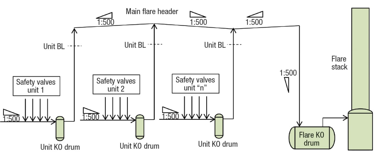
FIGURE 6. This schematic shows a closed pressure-relief system using the alternative suggested here
Further integration of the ISBL and OSBL flare projects can bring gains by considering the pressure profile of the main flare header determined by the refinery-flare design case. The pressure at the battery limit of the process unit farthest from the flare unit will be higher than the process unit closest to the flare unit. In the traditional approach, the maximum pressure at the battery limits of all the process units is defined as a constant value and is the same for all process units. Taking this into consideration, this profile permits that the process units nearest to the flare unit can reduce the diameter of the ISBL flare headers until the maximum permitted back pressure is reached for the most critical pressure-safety valve (PSV). Normally the most critical PSV is the valve with the lowest set pressure. All ISBL headers should be designed for the maximum possible velocity and values of over 35% of the Mach number should be pursued, but limited to 50%, and approximately maintained along the ISBL header, by adjusting the diameter to minimize header costs. The main flare header should also be sized carefully, to minimize the diameter, by considering the maximum possible process-units battery-limit pressures defined by the back pressure of the PSVs. Once more, the diameter of the header should be adjusted to maintain the vapor velocity for the design case, which is approximately constant from the farthest process unit to the flare unit.
Cost savings
As can be seen from the above discussion focused on petroleum refineries, fairly simple project considerations can reduce the cost of construction of a closed pressure-relief system. It is possible to significantly reduce the size of the process-unit KO drums, while at the same time save considerable structural steel used for the ISBL and OSBL pipe racks. It is also indicated that by careful calculations of the closed flare system with integration of the ISBL with OSBL, it is possible to reduce the flare header diameters. In comparison with the traditional approach, this new manner to project the pressure relief system offers a reduction of about 30% in the height of the main flare header and around 20% in the height of the unit flare headers. This together with the much smaller unit KO drums, reduced header diameters and less process piping for the lowered air coolers, permits an investment cost reduction for the relief system of up to 20% as compared with the traditional project.
♦ Edited by Dorothy Lozowski
References
1. Mukherjee, S., Pressure-Relief System Design, Chem. Eng., November 2008, pp.40–45.
2. Pressure-Relieving and Depressuring Systems, API Standard 521, Fifth Edition, January 2007 and Addendum, May 2008.
Author
 Peter Cain is a process consultant for Petrobras in Brazil (Phone: 55-21-98211-0627; Email: [email protected]). He has more than 40 years of experience in positions including process engineer, job leader, technical coordinator, technical manager, principal partner and consultant in the petrochemical, petroleum, chemical, industrial waste and nuclear fields. For the past 16 years, he has worked with Petrobras on the installation of several industrial units in areas such as hydrogen generation, hydrocracker and hydrotreatment units, power generation, cooling-water towers, crude and vacuum distillation and others that are parts of modern petroleum refineries. He is also participating in the basic engineering and FEED projects of two, new 300,000-bbl/d refineries and has presented several project revisions to reduce Capex and Opex. He has also realized the “clean up” of several areas contaminated with oil as principal partner and founder of a waste treatment company. Cain holds an honors degree in applied physics from Bath University in England.