As world leaders agree on the need to reduce greenhouse gas (GHG) emissions, major milestones and new technologies point toward potential solutions
Last month, delegates from 195 countries converged on Paris, France for the 21st Conference of the Parties (COP21; November 30 – December 12) to the United Nations Framework Convention on Climate Change (UNFCCC). The goal of COP21 was to reach an international agreement on how to limit global warming by reducing or eliminating the emissions of greenhouse gases (GHGs). After all-night deliberations, the UNFCCC agreement — to hold the increase in the global average temperature to well below 2°C above pre-industrial levels and to pursue efforts to limit the temperature increase to 1.5°C above pre-industrial levels — was adopted by all parties on December 12.
The buildup to COP21
Already by last October, 120 countries had submitted to the U.N. their Intended Nationally Determined Contributions (INDCs), which are their national targets for reducing GHGs. The U.S., for example, intends to achieve “an economy-wide target of reducing its GHG emissions by 26–28% below its 2005 level in 2025, and to make best efforts to reduce its emissions by 28%.” The target covers all GHGs in the 2014 Inventory of the U.S. GHG Emissions and Sinks: CO2, CH4, N2O, perfluorocarbons (PFCs), hydrofluorocarbons (HFCs) SF6 and NF3. Similar INDCs were issued by: Japan (26% reduction of GHGs by 2030 compared to 2013 (25.4% reduction compared to 2005); Canada (30% reduction of GHG emissions below 2005 levels by 2030); and Australia (26–28% below 2005 levels by 2030). China pledged to peak emissions by 2030 and increase its share of non-fossil fuels in primary energy consumption to around 20%. The E.U. aims for at least 40% domestic reduction in GHG emissions by 2030 compared to 1990.
Achieving such targets will require the efforts and expenditures across all sectors of the chemical process industries (CPI): oil-and-gas (CO2 and CH4), petroleum refining (CH4 and CO2), chemicals (CO2, CH4, N2O), power generation and transmission (CO2, PFCs), semiconductor fabrication (SF6 and NF3), as well as iron, steel and cement making (CO2). Consumers, too, will ultimately feel the effects on their pocketbooks, with higher costs for electricity, more fuel-efficient transportation, and “greener” buildings. The priority areas listed by the parties submitting INDCs is shown in Figure 1.
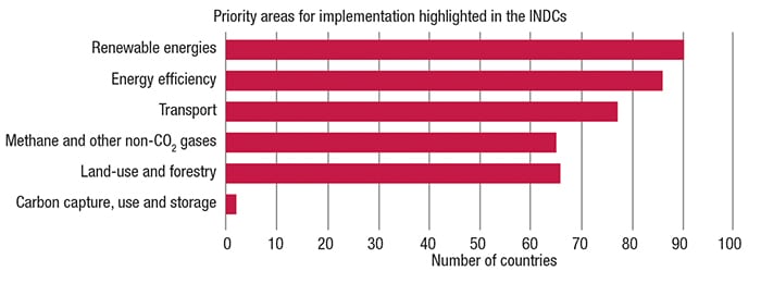
Figure 1. Renewable energies and energy efficiency were priorities for the majority of countries’ Intended Nationally Determined Contributions (INDCs; source: http//unfccc.int/files/adaption/application/pdf/all_parties_indc.pdf)
In the buildup to COP21, The Institute of Chemical Engineers (IChemE; Rugby, U.K.; www.icheme.org) Energy Center Board issued a statement (December 2) that outlines five priority topics for the climate talks: energy efficiency; energy storage and grid management; carbon capture, storage (CCS) and utilization; nuclear energy; and sustainable bioenergy. “The technologies exist now to deliver massive energy savings and GHG emissions reductions in all five priority areas. Taken together, they represent a pathway to a decarbonized energy system that can be realized now, as long as the agreement made at COP21 recognizes that the time has come for deployment of such technologies” (emphasis IChemE’s).
“Chemical engineers already understand the technology needed to limit atmospheric CO2 levels. Now is the time to start using it, says professor Stefaan Simons, chair of IChemE’s Energy Center. “World leaders can shift the focus from research and development (R&D) to demonstration and deployment. We can give policy makers the solutions needed to mitigate climate change,” he says.
This position was supported by U.N. Secretary General, Ban Ki-Moon during COP21, who said The solutions to climate change are on the table. They are ours for the taking. Let us have the courage to grasp them.
Progress in CCS
Because fossil-fuel-based power generation represents the largest source of CO2 emissions around the world, most experts and authorities agree that CCS will be required to prevent global temperatures from exceeding safe levels. However, two main challenges to widespread deployment of CCS technologies in the power sector are the need to bring down the cost to a level that sustains competition with low-carbon technologies and to establish plant sites where CO2 storage is available and economic, according to the 2015 World Energy Outlook Special Report: Energy and Climate Change, published last October by the International Energy Agency (Paris, France; www.iea.org). Nevertheless, efforts are continuing to address these two challenges, as well as increasing the acceptance of the technology.
Last September, the U.S. Department of Energy’s (DOE) National Energy Technology Laboratory (NETL; Morgantown, W. Va.; www.netl.doe.gov) released the fifth edition of its Carbon Storage Atlas (Atlas V), which shows prospective CO2 storage resources — in saline formations, oil and natural gas reservoirs, and un-mineable coal seams — of at least 2,600 billion m.t. — an increase over the 2,380 billion m.t. reported in the 2012 Atlas. This vast resource has the potential to store hundreds of years’ worth of industrial GHG emissions, permanently preventing their release into the atmosphere, says NETL.
New CCS milestones
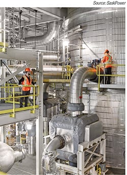
Figure 2. A view inside the CCS facility of
SaskPower’s Boundary Dam Unit 3 in Canada. This plant, with more than one year of operation, is the world’s first coal-fired power plant to capture and store the CO2 from the fluegas
CCS achieved an important milestone in the fall of 2014, with the startup of SaskPower’s Boundary Dam Unit 3 (120 MW) in Canada (Figure 2) — the world’s first commercial power plant to come online with CO2 capture (for more details, see CO2Gets Grounded, Chem. Eng., April 2014, pp. 21–23; www.chemengonline.com/co2-gets-grounded).
More recently (last November), Fluor Corp. (Irving, Tex.; www.fluor.com) completed the construction of Shell’s (The Hague, the Netherlands; www.shell.com) Quest CCS project near Fort Saskatchewan, Alberta, Canada. The Quest CCS project is designed to capture more than 1 million m.t./yr of CO2 from the Scotford Upgrader, which turns oil-sands bitumen into synthetic crude oil. The CO2 from the upgrader’s hydrogen-production plant is captured by an amine solution, and then released and liquefied so it can be pipelined 65 km north to be injected 2 km underground for permanent storage.
The governments of Alberta and Canada have invested significantly in Quest, contributing $740 million (Canadian) and $120 million, respectively. Effective government support and robust regulatory frameworks will continue to be critical to accelerating the momentum of CCS implementation worldwide, says Shell.
As part of the funding agreement, Shell is sharing information online (www.energy.alberta.ca/CCS/3848.asp) about Quest’s design, processes and lessons learned to help make CCS technologies more accessible and drive down costs of future projects.
Meanwhile, Mitsubishi Heavy Industries, Ltd. (MHI; Tokyo, Japan; www.mhi-global.com), the Japan Research Institute, Ltd. (www.jri.co.jp) and Inpex Corp. (www.inpex.co.jp; all three Tokyo, Japan) submitted a proposal to the Mexican Ministry of Economy, Trade and Industry (METI) to study the feasibility of a CCS-EOR project in Southern Mexico. The study — expected to be completed in March — will be based on the KM CDR process, which uses the high-performance KS-1 solvent that MHI and Kansai Electronic Power Co. co-developed ( Chem. Eng., January 2004. p.13; www.chemengonline.com/articles.php?file=2004%2FNewsChem%2FNewsChem01012004_03.html).
The KM CDR process is also featured in a number of CCS projects, including what is said to be the world’s largest post-combustion CO2 system for a coal-fired power plant in Texas. Scheduled for startup in early 2017, the system will have a CO2-capture capacity of 1.4 million m.t./yr. The CO2 that is captured from fluegas of Unit 8 of NRG Energy Inc.’s (Houston; www.nrg.com) WA Parish generation station — a coal-fired power plant located about 60 km southwest of Houston — will be transported through about 80 km of pipeline to be used for enhanced oil recovery (EOR) at the nearby West Ranch oil field to boost crude oil production. As of September 2015, the engineering, procurement and construction (EPC) activities are over 60% complete, and construction is on schedule, with over 50% of the pipe installed, according to the DOE.
Meanwhile, efforts continue to find more efficient solvents to capture CO2, as regularly reported in the Chementator department of this magazine. Linde Group (Munich; www.linde.com), for example, is involved in a joint pilot-scale project with BASF SE (Ludwigshafen, both Germany; www.basf.com) to test solvent-based advanced technology for the improved economic capture of CO2 from fluegas. This is taking place at the National Carbon Capture Centre (NCCC) in Wilsonville, Ala. The innovative technologies being tested integrate an advanced aqueous amine-based solvent and CO2 capture process technology from Linde. The new solvent, OASE blue from BASF is an alternative to the standard monoethanolamine MEA), a benchmark solvent employed in fluegas CO2-capture applications. The process-related innovations from Linde incorporated into the project include: gravity-driven instage absorption column cooler; high-capacity structured packing; advanced emission-control wash loop; placement of a reduced-size fluegas blower downstream of the absorption column; and higher pressure stripping of the captured CO2.
According to Linde, operations and testing since January 2015 have already validated several performance targets set. A CO2 capture rate exceeding 90% with a purity rate exceeding 99.8% is being achieved. The regenerator has also been operated at pressures up to 3.4 bars, which is a first for this technology. The higher pressures offer reduction of the downstream CO2 compression energy as well as compressor capital costs. The testing has also validated the functional performance of all the process innovations, says Linde.
A ‘cool’ method to recycle CO2
Last November, Air Liquide (Paris, France; www.airliquide.com) launched its Cryocap technology — a cryogenic process that captures CO2 released during H2 production. Connected to Air Liquide’s largest H2 production unit in France, located in Port-Jérôme, Notre-Dame-de-Gravenchon (Normandy), Cryocap represents an investment of around €30 million that was decided by the Air Liquide Group in 2012, with an €9-million support from Haute Normandie region, the community of Caux Vallée de Seine communes, and ADEME (French Environment and Energy Management Agency) through the Programme d’Investissement d’Avenir, a program for investment for the future.
Developed jointly by Air Liquide R&D and Engineering & Construction teams, Cryocap made its commercial debut on Air Liquide’s steam methane reformer (SMR), which has been supplying approximately 50,000 Nm3/h of H2 to the neighboring petroleum refinery, Esso Raffinage SAF (ExxonMobil group). The Esso refinery uses the H2 to remove the sulfur content of the automotive fuels.
As seen in Figure 3, the SMR produces synthesis gas (syngas; a mixture of H2 and CO), which is then converted to a H2-rich gas in a water-shift reactor. The H2 is then purified in a pressure-swing-adsorption (PSA) unit. The Cryocap H2 unit captures CO2 from the (PSA) offgas. The offgas is filtered, compressed and dried in an adsorption unit, and sent to a cryogenic purification unit, where the CO2 is separated from the other components by a combination of partial condensation and distillation. A pure and pressurized CO2 stream is produced from the cold box. Noncondensed gases are recycled through a membrane system to recover H2 and CO2. Membrane residual gas is sent to the burners of the SMR, and H2-rich gas is recycled to the PSA inlet, which increases the overall H2 production.
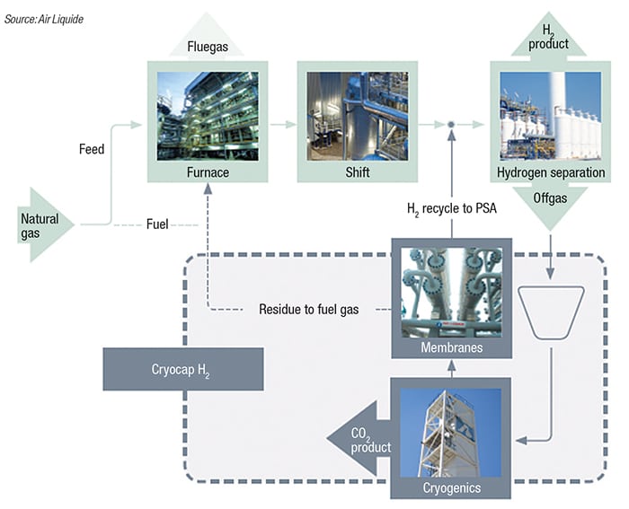
Figure 3. The Cryocap H2 process marked its commercial debut at Air Liquide’s steam-methane reformer (SMR), which generates H2 for a nearby petroleum refinery. The captured CO2 is purified and liquified for a number of applications
Cryocap is said to be first CO2-capture technology using a cryogenic process. After being purified, the captured CO2 can be used to meet a variety of industrial needs for carbonic gas supply (carbonation of beverages, food preservation and freezing, and so on). At this site, the Cryocap unit has a capture capacity of 100,000 m.t./yr of CO2.
The company also has two additional Cryocap processes for recovering CO2 from the offgases of steel plants (Cryocap Steel) and thermal power plants (Cryocap Oxy). Although the cost of CO2 capture depends on project specifics, Air Liquide says Cryocap delivers the lowest cost of CO2 production among industrial sources, in particular, when compared to traditional technologies, such as amine-based absorption processes.
A ‘carbon-negative fuel’
At COP21, Carbon Wealth Scandinavia AB (Stockholm, Sweden; www.skymining.com) launched its so-called SkyMining technology, which the company has now demonstrated and is ready for commercialization and scaleup. In SkyMining, a fast-growing, special strain of Elephant grass is used to “extract” CO2 from the atmosphere. The grass grows about 4 m per 100 days on marginal land, and can be harvested at least twice a year, explains the Carbon Wealth director Rory McMeekin. After harvesting, the biomass is then processed by a proprietary thermal-carbonization process into a solid fuel dubbed CNF (for carbon negative fuel). CNF has an energy content that is up to 30% higher than dry wood and brown coal, and costs about half that of heating oil, is cheaper than charcoal, and is competitive with coal, says the company. CNF also has the same grindability and shape as coal, making it suitable for co-firing, the company adds. Production of CNF has been demonstrated at the 1-m.t./h scale, and is ready for scaleup, says McMeekin.
What makes CNF earn its “carbon negative” title is the fact that about 20% of the CO2 captured from the atmosphere remains stored underground in the root system of the grass, says McMeekin. Each hectare of grass planted on marginal land can sequester and store over 14 m.t./yr of CO2. There are vast areas of unused land on which the grass could be grown, and after a number of seasons, the once-marginal land will be transformed into fertile cropland due to the carbon that is returned to the soil, says McMeekin. “This is a natural, holistic approach to producing a clean, sustainable fuel while reducing CO2 in the atmosphere.”