Rotary valves are used almost universally in pneumatic conveying systems. They serve three main functions: 1) to provide a pressure-seal (airlock) between two adjacent processes, 2) to provide solids metering (feeding) and 3) to provide a combination of solids metering and a pressure-seal for feeding solids into a pneumatic conveying system.
Rotary valves are common devices for feeding solids into a pneumatic conveying pipeline, and they function in different ways in different circumstances. For instance, rotary valves can function as follows:
• As an airlock at locations where an air-seal is needed, such as at the end of a pneumatic conveying system where the conveyed solids are discharged from a receiving vessel into a storage hopper, bin or silo
• As a feeder when they are used to discharge a fixed or a variable volumetric flow of solids from an upstream process to a downstream process
• As a combination airlock and a feeder when they meter solids into a pneumatic conveying pipeline
Key aspects of how rotary valves are designed and used are discussed below.
Types of rotary valves. Rotary valves are generally made in the following three varieties:
1. Drop-through type
2. Off-set or side-entry type
3. Blow-through type
 |
|
FIGURE 1. In a drop-through valve, the solids inlet and solids outlet are
typically the same size and are vertically aligned. As the rotor turns, the empty rotor pockets are filled by solids that flow vertically down from a hopper located above the valve |
In a drop-through valve (Figure 1), the solids inlet and outlet are vertically inline and are generally of the same size. When the rotor starts to turn, the empty rotor pockets are filled by the solids flowing vertically down from a hopper above the valve. These valves can have square, rectangular, or round inlets and outlets; the square shape is more common because it provides a larger opening area compared to a round-shaped opening.
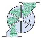
In a side-entry valve (Figure 2), the solids inlet is offset from the vertical, solids-gravity-flow line by 30 deg. This offset allows the upcoming empty rotor pocket to fill only partially when the rotor turns past the valve inlet. This partial filling minimizes shearing of the solid particles that sometimes get trapped between the rotor and the valve housing. Partial filling also prevents jamming or seizing of the rotor by solid particles that sometimes becometrapped between the rotor and the valve housing. The volumetric fill efficiency of the empty pocket depends on the solid’s flow properties, but it is generally about 60%. These valves should have an adjustable slide plate in their inlet section to allow for the increase or decrease of pocket filling.
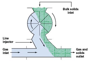
Blow-though valves are similar to drop-through valves except that they are installed directly in the conveying line without any intermediate device.In this design, the conveying gas enters from one end of the rotary valve, blows through the emptying rotor pocket, and carries the solids to the opposite end of the rotary valve and directly into the conveying line. These valves are used for materials that are sticky and have difficulty in flowing out from the rotor pocket.
Rotary valve construction. Rotary valves have three main components: A cylindrical body with both ends closed, a horizontal rotor that rotates inside this body, and a drivetrain that drives the rotor. These components are described below:
Rotary valve body. The valve body is a horizontal cylinder with a top inlet and a bottom outlet, and with vertical plates to close both sides of the cylinder. The body is generally cast from a metal such as cast iron, carbon steel, stainless steel or aluminum, although other materials are used for special applications, such as very high temperatures or highly abrasive solids. All internal surfaces of the cylindrical body are made smooth by polishing or chrome-plating because smooth surfaces are needed to maintain the required tight clearances between the valve body and the rotor. A surface finish of 2B is desirable.
The valve rotor is of welded- steel or stainless-steel construction with eight or more pockets. Its horizontal shaft is also steel or stainless steel.
The entire valve is designed to withstand the maximum and minimum pressures and temperatures to which the valve will be exposed. These include both process and ambient conditions.
To maintain the required clearances, in locations where the valve is exposed to extremely low temperatures (such as –40°F), the valve body is jacketed, heated and insulated. The heating medium is a heat-transfer fluid that is circulated throughout the body to maintain a constant and uniform temperature. Alternatively, the valves can be installed inside heated enclosures that are provided with easy access for the valve’s inspection and maintenance.
In locations where temperatures are not extreme, electrically heated blankets placed over the valve body can be used to maintain a uniform body temperature.
 |
|
FIGURE 3. In an open-bottom rotary valve, solids that may
have entered the clearance between the rotor ends and valve body are allowed to drop out. This option is not viable for feeding solids into positive-pressure conveying systems, but they are suitable for vacuum-type conveying systems, such as airlocks |
 |
|
FIGURE 4. Closed-bottom rotary valves are widely used in
pneumatic conveying applications because they provide a good air seal between the rotor edges and the valve body |
The valve bottom may have an open or closed space between the rotor and the valve body. As shown in Figure 3, open bottoms allow solids that may have entered the clearance between the rotor ends and the valve body to drop out. Open-bottom rotary valves are unsuitable for feeding solids into positive-pressure-type conveying systems, because they allow the conveying air to flow upward into the clearances, thereby increasing the potential for conveying air leakage. These valves can be used in vacuum-type conveying systems such as airlocks, or as a feeder. In most pneumatic conveying applications, closed-bottom rotary valves, such as that shown in Figure 4, are more commonly used because they provide a better air seal between the rotor edges and the valve body.
For feeding coarse particles such as plastic pellets, drop-through rotary valves are provided with a well-configured inlet plow in their inlet section. This plow prevents solids from entering the clearance between the rotor and the valve housing, thereby preventing the resulting jamming or seizing of the rotor. The plow is V-shaped, is cast or welded into the downstream side of the rotary valve inlet, and directs the solids flow into the rotor pocket.
Rotors. Rotors are of welded construction with rectangular-shaped blades that are welded to a shaft. Blades are evenly spaced around the rotor, forming triangular pockets. The bottom of the pockets can be flat or curved, depending on whether the solids are free-flowing or sticky.
The number of blades is at least eight for any size rotary valve. Large size valves, such as thouse with 4 ft3/rev. capacity or larger, can have have 10 or 12 blades.
Blade tips are generally hardened with stellite or tungsten carbide to reduce their wear. When handling coarse solids, such as plastic pellets, tips are generally relieved at a 45-deg angle on their trailing edge to prevent clipping of the pellets and the resulting binding of the rotor inside the valve housing.
The two ends of the rotor can be open or closed. In open-end rotors, rotor pockets are fully open on both ends. In closed-end rotors, rotor pockets are fully closed by full-size plates that are welded at each end. Blades are welded to the shaft and also to the two end-plates, thereby providing strength and rigidity to the rotor. Closed-end rotors are, therefore, more rigid and sturdy, and are less prone to flexing and bending under high differential pressures than open-ended rotors. They are used for a large variety of materials. Open-ended rotors cost less but are more susceptible to bending and rubbing with the internal surface of the valve housing, resulting in its wear and erosion.
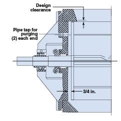
In closed-end rotors, the clearance space between the end plates and the valve housing is generally about ½ to ¾ in.
Rotary valve drive. Rotary valves are generally driven by a gear-head motor, instead of by a separate motor and a gear box, because this method is more economical. The gear-head motor reduces the output speed to about 30 rpm. From this motor, the rotary valve rotor is driven by chain and sprockets to arrive at the valve speed that is needed. This motor can be installed either at right angles to, or parallel to, the rotary valve. Parallel installation with a chain-and-sprocket drive is preferable because valve speed can be changed easily by changing sprockets. Right-angle installation is more difficult because it requires changing of worm gears to change the speed.
The rotary valve shaft extends beyond the side plates of the valve housing using outboard, spherical-roller, dust-sealed-type bearings between the shaft and the housing. For shaft packing, a long-wearing material such as Teflon with Neoprene gaskets is typically used. The normal speed range of rotary valves is 15 to 22 rpm. For rotary valve sizing, the typical speed used is 16 rpm.
Rotary valves used in continuous production operations are provided with a zero-speed motion switch that is installed on the driven shaft to detect chain breakage and the resulting valve stoppage.
Rotary valve pressure rating.For pneumatic conveying systems, rotary valves are designed so that the rotor can withstand the maximum pressure differential across the valve’s inlet and outlet. In most cases, this pressure is 15 psi for dilute-phase conveying systems. However, instead of using 15 psi, the differential pressure rating should be based on the actual design pressure of the conveying system.
Deflection of the rotor at the midpoint of its axis due to this differential pressure drop must not exceed 0.001 in.
The internal vacuum or pressure rating of the rotary valve housing should be 10% higher than the maximum operating vacuum or pressure to which the housing will be exposed. Most standard rotary valves have a 150-psig housing design pressure.
Rotary valve clearances.Clearances between the rotor and the rotary valve body must be as small as possible, and they must be concentric. Typically, circumferential clearances are between 0.004 and 0.008 in., and end-clearances are 0.006 to 0.0010 in. To minimize conveying gas leakage, the design clearances should be the lower value of these ranges.
Binding or seizing of the rotor inside the housing should be prevented by maintaining these minimum clearances at the highest and lowest operating temperatures of the incoming solids and of the ambient conditions.
The rotary-valve vendor should perform tests to measure the clearances, and the air leakage as a function of rotary valve speed, before the valve is accepted for use. This test should be run under the actual operating conditions, such as ambient and process temperatures and pressures. Hot air may be needed to heat the valve when it is operated under temperatures higher than the ambient.
Leakage-venting methods.In pressure-type conveying systems, pressurized conveying air that fills the returning empty rotor pockets is carried over to the inlet side of the rotary valve. To prevent this air from interfering with the flow of incoming solids, this air is vented out from the valve before it reaches the valve inlet. This is done by providing a vent port on the return side of the valve body. To prevent increasing air leakage, this vent port is located so that there are at least two rotor pockets between the valve bottom and the vent port. The vent port size should be large enough to completely vent out the entire air volume contained in the rotor pocket. For large valves, a rectangular-shaped vent port about one-half the length of the pocket width is recommended.
When conveying powders or fine granular materials, air that is vented out from this vent port may contain significant amounts of these solids. To prevent their loss, these materials should be fed back into the rotary valve using a properly designed vent hopper installed at the rotary valve inlet.
 |
|
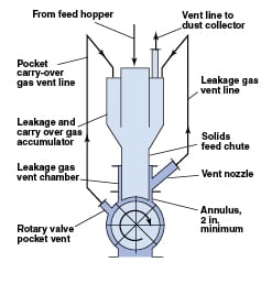
FIGURE 5. This installation shows a rotary valve venting system for a dilute-phase conveying system, to evacuate
leakage between the rotor and valve housing. The solids-feed chute extends into the rotary valve, as shown. The feed chute’s bottom matches the outer contour of the rotor with a space of 1/8–1/4 in. between it and the rotor. A leakage gas vent chamber is installed above the rotary valve. The annulus between the feed chute and this vent chamber is 2-in. minimum. Leakage gas flows into ths annulus and exits via a vent nozzle to a dust collector and exhaust fan |
In addition to the carryover air described above, there is also air leakage from the circumferential and end clearances between the rotor and the valve housing. These leakages should be vented out so that they do not interfere with the flow of incoming solids. This is done by using a specially designed insert that extends from the inlet of the valve up to its rotor tips. This insert provides an annular path between the insert and the valve body to vent out the leakage air. This insert should extend from the inlet of the rotary valve up to the rotor surface with a gap of about 1/8 in. between the rotor and the insert. Details of this venting method are shown in Figure 5 for dilute phase systems and in Figure 6 for dense-phase systems.
Leakage-calculation methods.Complete information on rotary valve leakage calculations can be found in Ref. [1].
The flowrate of clearance leakage can be calculated using Equation 1:
(1)
Q = Leakage flowrate, ft3/s
C = Orifice constant = 0.5
A = Clearance area, ft2
g = Gravitational constant, 32.2 ft/s2
dp = Pressure differential across the rotor, lb/in.2
As shown in Equation 1, leakage flow is directly proportional to the clearances between the rotor and the valve housing. For medium-sized rotary valves, this clearance is 0.004–0.006 in., or 0.10–0.15 mm.
The flowrate of carryover air can be calculated by using the following relationship:
Carryover air flowrate (ft3/s) equals Rotor displacement (ft3/rev) multiplied by rotor speed (rpm/60)
 |
|
FIGURE 6. Air leakage between the rotor and the valve housing
must be vented so that it does not interfere with the flow of incoming solids. In this venting installation, for a dense-phase conveying system, a solids-feed chute extends into the rotary valve, as shown. The feed chute’s bottom matches the outer contour of the rotor with a space of 1/8 in. between it and the rotor. A leakage gas-vent chamber is installed above the rotary valve. The annular space between the feed chute and this vent chamber is 2 in. minimum. Leakage gas flows into this annular space and exits via a vent nozzle to the top of the leakage gas and pocket carryover gas accumulator. Carryover gas from the rotor pocket and body vent is also vented to this accumulator
|
 |
|
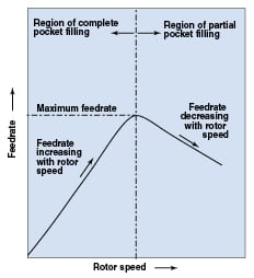
FIGURE 7. Rotor speed impacts the feed rate of a rotary
valve, as shown here. Theoretically, the solids-throughput rate should increase linearly with valve speed, although as shown here, the feed rate decreases after reaching a maximum rate over a typical speed range of 15–22 rpm |
Rotary valve capacity.Figure 7 shows the solids-throughput rate attainable in a rotary valve versus rotor speed. Theoretically, the solids throughput should increase linearly with the valve speed — that is, with the number of valve rotations.
In practice, however, throughput increases only up to a maximum value, and then starts to reduce when the speed is further increased. This happens because while falling from the rotor pocket to the valve bottom, solids face both gravitational and centrifugal forces. At high rotor speeds, because of centrifugal forces, some of the solids remain in the emptying pocket. This results in reduced fresh material that can flow into the valve inlet, thus reducing the fill efficiency of the valve.
The capacity of a rotary valve (CFR) is calculated using Equation 2. It is expressed as volumetric flow per revolution of the rotary valve (ft3/rev of solids flow):
(2)
where:
CFR = Capacity of a rotary valve, ft3/rev
W = Solids flowrate, lb/h
δB = Solids bulk density, lb/ft3
N = Valve speed, rpm
E = Pocket-fill efficiency
Pocket-fill efficiency.Shown below are typical pocket fill efficiencies for different types of rotary valves:
• Side-entry rotary valve: 40– 60%
• Drop-through, flood-fed valve: 60– 80%
• Drop-hrough, flood-fed valve with body vent and leakage-air inlet insert: 90–95%
In general, the following factors provide better fill efficiencies:
• Lower valve speeds
• Lower Δ P across the valve
• Proper venting of the leakage gases from the rotary valve
 |
|
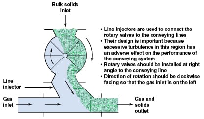
FIGURE 8. When the rotary valve is used to feed solids into a conveying line, the rotary valve and the
line injector below it are perpendicular to the conveying line. |
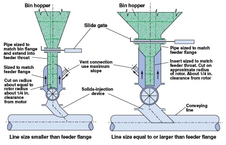
Rotary valve installation. Rotary valves that are used to feed solids into a conveying line are installed such that the rotary valve and the line injector below it are perpendicular to the conveying line (Figure 8). A line injector is used to connect the rotary valve to the conveying line. Its design is important because excessive turbulence in this region has an adverse effect on the performance of the conveying system.
In pressure-type conveying systems, any intermediate spool pieces between the rotary valve and the line injector, or between the line injector and the conveying line, should not be used because the resulting air turbulence can adversely affect the flow of solids into the conveying line.
The direction of rotation of the rotary valve should be clockwise when facing the valve, such that the conveying air enters the conveying line from the valve’s left side.
Rotary valves in dense-phase pneumatic conveying. Presently, rotary valves used in dense-phase pneumatic conveying are designed to withstand differential pressures up to 6 bars and maximum solids feed rates of about 5,000 ft3/h. High circumferential clearance leakage that occurs due to these high pressures is minimized by increasing the number of rotor blades. Some good designs have as many as 24 blades.
Rotor-end leakage is prevented by using a specially designed, gas-tight seal between the rotor and valve body. A well-designed venting system to properly vent out the clearance leakage air and the rotor carry-over air is a necessity for these high-pressure-drop rotary valves.
Rotary valves with special features. Rotary valves are made with special design features for applications such as food grade installations, those requiring quick and easy access for cleaning, those handling corrosive, abrasive or sticky materials, those handling very high or very low solids or ambient temperatures, but the basic design principles described above still apply to these designs. n
Reference
1. Agarwal, Amrit, “Improving Rotary Valve Performance,” Chem. Eng., March 2005, pp. 29–33.
Author

Amrit Agarwal is a consulting engineer with Pneumatic Conveying Consulting (7 Carriage Rd., Charleston, WV 25314; Email: [email protected]). He retired from The Dow Chemical Co. in 2002 where he worked as a resident pneumatic conveying and solids-handling specialist. Agarwal has more than 40 years of design, construction, operating and troubleshooting experience in pneumatic conveying and bulk-solids-handling processes. He holds an M.S. in mechanical engineering from the University of Wisconsin, Madison – Wisconsin, and an MBA from Marshall University (Huntington, West Va.). He has written a large number of articles and given classes on pneumatic conveying and bulk solids handling.