Single-fluid heat-transfer systems that both heat and cool a process require special considerations for trouble-free operation
Thermal fluid systems that both heat and cool are often utilized in batch processes. They are also often found in continuous processes where heating is required at one point in the process and cooling (often for the purpose of heat recovery) is required in a different part of the process. Because these systems utilize the same fluid for both the heating and cooling process, they are collectively referred to as “single fluid systems.” This article discusses considerations specific to the design and operation of single fluid systems, although some of these considerations are more widely applicable.
Single fluid systems can operate in an efficient and trouble-free manner or they can subject the owner to operational inefficiencies and maintenance problems, depending on whether or not certain design and operational pitfalls are avoided. These heat-transfer systems can operate over a wide range of temperatures, from as high as 400°C (750°F) to temperatures well below –40°C (–40°F). A few heat-transfer fluids can actually accommodate most of this broad temperature range.
In this article, I discuss pitfalls and considerations for the very hot and very cold aspects of single fluid systems with the understanding that, as operating temperatures trend closer to ambient temperatures, operational concerns will be lessened; however attention paid to these considerations for all systems can improve performance and reliability.
Single fluid systems can be heated directly, as with electrically heated systems (Figure 1) or indirectly, as with secondary loop designs that receive heat, normally by direct injection of hot thermal fluid from a central source (Figure 2). Careful attention to the components of the system can contribute to reliable operation with good performance and low maintenance costs.
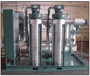
Figure 1. This packaged single-fluid system heats fluid directly with the two electrically heated heat exchangers in the foreground. The cooling heat exchanger (horizontally mounted behind the heating units) cools fluid that is diverted through it by a control valve. Fluid is motivated by a pump that is not visible in this image. When installed, this unit will have
an expansion tank mounted, either to the unit or nearby
Heat Exchange and Transfer
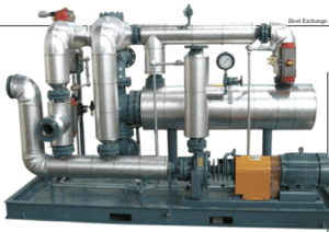
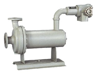
Figure 2. This packaged single-fluid system is heated indirectly by direct injection of hot fluid from a central source. The cooling heat exchanger (horizontally mounted behind the pump) cools fluid that is diverted through it
by a control valve. The pump maintains alignment by having the casing supported at its centerline. The pump is also air-cooled (note the fins), and the mechanical seal is protected from extreme temperatures by being located
at the rear of the pump
Heat Exchange and Transfer
Thermal fluid selection
I have maintained for a long time that the selection of the thermal fluid is the most-important single decision to be made in the design and specification of a thermal fluid system, and nowhere is it more important than in single fluid systems.
For heating-only systems, it is common practice to evaluate potential thermal fluids by comparing maximum-allowable bulk- and fluid-film temperatures. The fluid’s vapor pressure should be considered for expansion tank and pump NPSH (net positive suction head) considerations. Resistance to oxidation is also important.
The evaluation of the thermal fluid for low temperature operation is also extremely important. Here, we are looking beyond the basic lowest temperature where the fluid is “pumpable”. Pumpability is a consideration for start-up in heating-only systems, but when the system is expected to efficiently cool the process, the fluid should be significantly warmer than its minimum pumpability temperature. The consideration here is viscosity. A fluid may be pumpable at a viscosity of one hundred to several hundred centistokes viscosity, but high viscosity makes for a low Reynolds number and a poor fluid-film heat-transfer coefficient. Significant attention should be paid to the viscosity and flow characteristics of the fluid at the minimum temperature that the fluid is expected to cool the process.
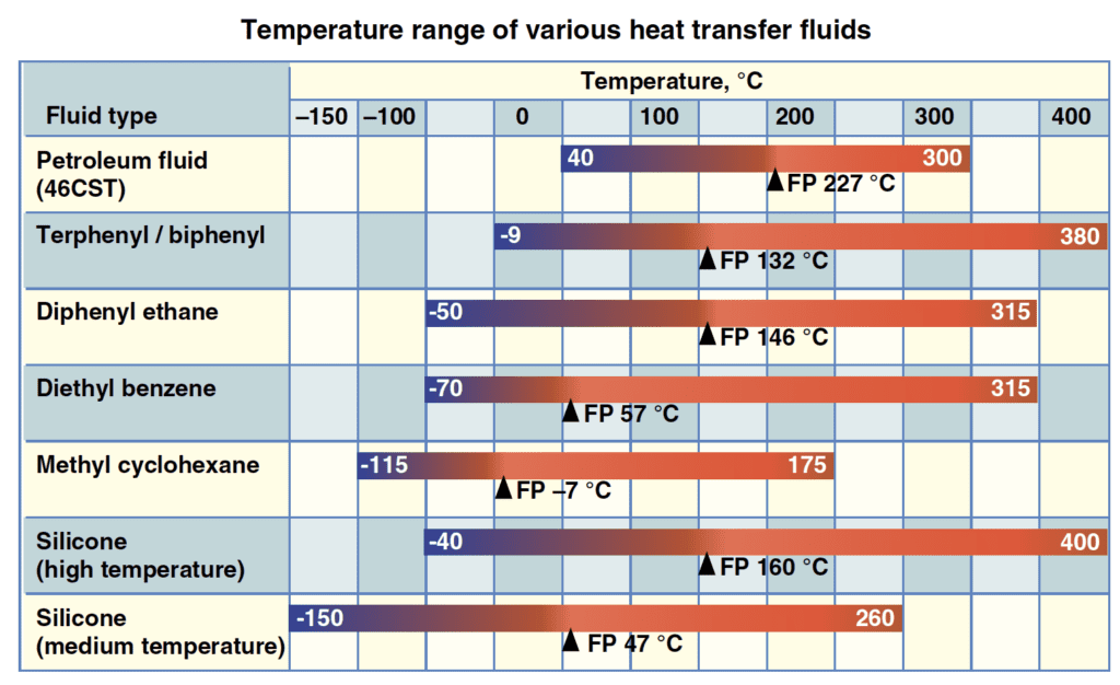
Figure 3. This chart shows the temperature range of a typical petroleum-based
“hot oil” plus several synthetic aromatic fluids and two silicone-based fluids
(FP is flashpoint)
Careful attention to the fluids available, and evaluation of fluid properties as compared to the individual demands of the single fluid system can have a significant effect on the longterm performance of the system (Figure 3). Classes of fluids include the following:
Petroleum-based fluids: The so-called “hot oils” are widely used in industry and can be used successfully in single fluid systems. There is a cost advantage to using these fluids, but most are limited (at the hot end) to 300°C (572°F) and do not give good cooling performance below 40°C (100°F). There are petroleum fluids that perform well above 300°C and other formulations that perform at lower temperatures.
Synthetic aromatic fluids: These fluids are manufactured rather than refined, and offer extended temperature performance at both high and low temperatures. Some of these fluids have very low viscosities at low temperatures, which allows high Reynolds numbers (and relatively high heat-transfer coefficients) to be maintained at low temperatures. Low temperature performance can be extended to as low as –115°C (–175°F) with these fluids. At the high-temperature end of the spectrum, these fluids can be more stable at high temperatures and allow heating to temperatures as high as 400°C (750°F). There is no fluid that can achieve heat transfer performance at both –100°C and +400°C, but aromatic fluids are available with usable temperature ranges as broad as 400°C (720°F). These fluids are often more expensive than petroleum-based fluids, but their extended performance and higher thermal stability offer value to many users.
Silicone fluids: Silicone fluids offer advantages of very wide, useable temperature ranges and low toxicity. One fluid has a range of almost 800°F (–40 to +750°F). Silicone fluids are high performance fluids and carry a price to match. They are very manageable in properly designed systems. Silicone fluids can develop significant vapor pressure at high temperatures and, in the author’s experience, can be more prone to leakage than other fluids. However, proper system design and a good piping-material specification can help make a very reliable and robust system.
There are other classes of fluids, including glycol-based fluids and fluorocarbon-based fluids, but they are not discussed in detail in this article.
Pumps
The pump is almost always the component requiring the most maintenance in a thermal fluid system, and is deserving of considerable attention when a new single-fluid system is being specified, or an existing system is being upgraded.
There are three pump applications in single fluid systems:
1. The heating (or hot- fluid-circulating) pump
2. The cooling pump, which may circulate thermal fluid or cooling water, depending on temperatures and system design
3. The single fluid pump, which will undergo the temperature swings associated with heating and cooling the process
Not all single-fluid systems have three pumps, because the applications are often combined. For instance, on smaller systems, the hot-fluid pumping application and the single-fluid pump application can be combined into one pump.
This article concentrates on the single fluid pump, because it has the most demands placed on it due to the fact that it is in a constantly changing temperature environment. The items that should be taken into consideration when specifying a single fluid pump are explained here.
Thermal stress: As the pump changes temperature, the metal components of the pump will expand or shrink, according to the direction of the temperature change. Different parts may change at different rates, depending on the weight of the particular casting and the percentage of its surface directly in contact with the pumped liquid. Rapid temperature changes can cause different components to press against each other unevenly. Over time, this will result in maintenance problems or out-and-out failures.
Materials of construction: Construction materials are important in specifying a single fluid pump. While cast iron may be adequate for water pumps and even some light-duty chemical pumps, it is too brittle for heat transfer duty, as rapid temperature changes could cause a cast-iron casting to crack. Ductile iron, cast steel or stainless steel are better choices for materials of construction.
Alignment: Mechanical alignment is critical for long bearing and mechanical seal life. If a (end suction) pump has a conventional foot mount under the casing, the expansion of the casing under heating can push the centerline of the pump out of alignment with the motor. This allows vibrations that can shorten bearing and seal life.
To counteract these problems, pumps are available with “centerline mounts”, where the pump casing is supported from the horizontal centerline. This supports the casing at the shaft centerline and maintains alignment by allowing the casing to expand both up and down when temperature increases.
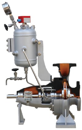
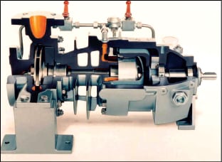
Mechanical seals: Mechanical seal specification and installation is deserving of considerable attention in single fluid pumps (Figure 4). Most pump “failures” exhibit themselves as mechanical seal failures, although the failure may not be the sole fault of the seal. If — when you remove a mechanical seal — the carbon face (or other rotating face) is not worn back to the shoulder, then the failure may not be the fault of the seal. Seal failure on hot pumps is often attributable to oxidation of the fluid as it migrates across the seal faces. The fluid degrades to carbon particles that either score the seal faces or agglomerate and force the faces apart, allowing the fluid to leak. There are many methods for addressing this problem, but one of the simplest and most-often used is to apply an inert gas quench to the back of the seal. The inert gas can be steam, nitrogen, carbon dioxide or another inert, non-oxidizing gas.
Seals that operate at cold temperatures (below 0°C) can leak as well, but not from fluid oxidation. Water can condense, and ice can form at the seal faces of cold seals, which can eventually force the seal faces open and allow a fluid leak. This problem can be a challenge to troubleshoot, because when the pump is removed from service for maintenance, the ice in the seal melts and the faces go back together. As with hot seals, an inert gas quench goes a long way toward mitigating the problem. Obviously, steam is not a good choice here, but nitrogen is used successfully in many cases.
Seals that operate near the pumped-fluid temperature can also wear abnormally if the temperature range of the system is large. This problem can be mitigated by environmental controls on the seal that stabilize the seal temperature, or by choosing a pump that locates the seal away from the pumped fluid.
Flange leaks: Low viscosity, high vapor pressure and low surface tension cause thermal fluids to be prone to leaking. A well-thought-out piping materials specification will go a long way toward reducing the possibility of leaks. One way to minimize leakage opportunities is to weld valves and fittings into the pipe, and to use bellows-sealed valves. Threaded connections on pipe and fittings are the least acceptable type of pipe joining in these systems. Where connections cannot be welded, as with pumps, the specification of 300-lb raised face flanges and the use of carbon- and stainless-steel spiral-wound gaskets significantly reduces the possibility of fluid leakage.
Sealless pumps
Mechanical seal problems can be avoided by using sealless pumps. The rotating assembly of a sealless pump is completely sealed from the outside, in a canister at the rear of the pump. The rotating-assembly bearings are lubricated and cooled by the pumped liquid.
Magnetic drive pumps employ a rotating magnet outside the can that is driven by a conventional electric motor. (Figure 5) The magnetic field of the driving magnet penetrates the metal of the can and couples with an internal magnet, which is part of the rotating assembly and drives the pump.
Canned motor pumps use a rotating assembly similar to those in magnetic drive pumps, except the internal magnet is replaced with a motor rotor winding (Figure 6). A three-phase motor winding is wrapped around the can. When the winding is energized, the pump operates like an electric motor. As with magnetic drive pumps, the rotating-assembly bearings are lubricated and cooled by the pumped fluid.
Sealless pumps (both canned-motor and magnetic-drive) have the advantage that they do not leak, but the user should be mindful of certain other aspects of sealless pump use. Sealless pumps use special materials of construction and have a significantly higher first cost than conventional pumps with mechanical seals. However, if they are properly specified, installed and operated, sealless pumps can enjoy a long service life that helps to offset their initial high cost.
Sealless pumps are more sensitive to suction conditions than their mechanically sealed cousins. They do not tolerate cavitation, slugging or dry running, and can fail quite dramatically if subjected to a significant diet of these conditions. Repair costs for failed sealless pumps can be quite costly. For these reasons, an installation utilizing sealless pumps should be carefully evaluated to avoid instances of cavitation, slugging or dry running.
Cooling protection
Cooling problems increase as the temperature difference (ΔT) between the thermal fluid and the cooling media increase. The cooling heat exchanger is normally a liquid-to-liquid heat exchanger where thermal fluid is cooled by water, although there are different approaches. The exchanger is generally rated at a temperature below the maximum temperature anticipated in the system in order to have an acceptable cooling rate at lower process temperatures. This presents a few interesting problems when the thermal fluid is at maximum temperature and the system transitions over to cooling mode.
If the heat transfer fluid is hot enough, and the ΔT is very high, the heat exchanger will operate at a heat transfer rate well above its specified rating. If the temperature is high enough, the cooling water can actually boil on (or in) the tubes. Depending on cooling water quality, this can allow scaling to occur on the tubes and eventually lower the efficiency of the heat exchanger and require expensive chemical cleaning. Another possibility, again depending on water quality and condition, is to have corrosion on the tubes, which will eventually lead to a tube leak.
When operating at high thermal-fluids temperatures, and above the specified rating of the heat exchanger, it is also possible to overheat the water returning to the tower. This problem is particularly important if the user goes to a dedicated cooling tower, because the cooling-water-return temperature can exceed the maximum temperature rating of the tower. If the tower has a plastic fill, the plastic can actually soften and sag in the tower. More than one tower has been rebuilt as a result of high cooling-water-return temperatures.
Chillers are sometimes used to directly cool the thermal fluid, particularly if cold temperatures are required to finish the batch. Chillers are also used to avoid maintaining a cooling tower. Again, serious (and sometimes expensive) problems can surface if fluid supply temperature exceeds the maximum allowable temperature of the chiller. Problems can range from reduced service life of the chiller to out-and-out catastrophic failure.
To avoid these pitfalls, consideration needs to be given to methodologies that guard against extreme temperatures. This can generally be accomplished by the use of flow-control and recirculation strategies, along with careful specification of heat exchangers, cooling towers and chillers. The benefits realized will be reduced maintenance and longer life of critical equipment.
Edited by Dorothy Lozowski
Author’s note:
Pictures included in the article are printed with the permission of the manufacturer. Use of these pictures does not constitute an endorsement of the product. When specifying equipment for thermal fluid systems, the reader should employ experienced resources, either internal or external, to insure that recognized and generally accepted good engineering practice is followed and that local and national codes and standards are complied with.
Author
 Jay Hudson is the principal consultant of J. G. Hudson & Associates (P.O. Box 4064, Salisbury, N.C. 28145-4064; Website: www.projeng.com; Email: [email protected]; Phone: 704-637-1714), a specialty firm concentrating in thermal-fluid consulting services. Hudson is a professional engineer licensed in the state of North Carolina with 35 years of experience in the chemical process industries (CPI) and concentrates his efforts exclusively in the area of thermal-fluid-system design, specification and operation. He was recently appointed to the NFPA Technical Committee on Fluid Heaters (NFPA 87).