Waste heat recovery (WHR) is essential for increasing energy efficiency in the chemical process industries (CPI). Presently, there are many WHR methods and technologies at various stages of implementation in petroleum refineries, petrochemical, chemical and other industry sectors. Increasing energy costs and environmental concerns provide strong motivation for implementing more and newer methods and technologies for WHR.
Most of the literature on this topic is based on individual methods and techniques, but there is a need for an integrated approach. The main objective of this article is to provide a review of promising methods and technologies for WHR (up to 400C) as a ready resource that can be used for better understanding and preliminary selection of suitable WHR techniques. To this end, various WHR practices in industry and in the literature are compiled and analyzed for their implementation benefits and constraints. Accordingly, the scope of this study includes a comprehensive review of various applicable WHR methods and technologies for the CPI (especially petroleum refineries), and guidelines for implementing the selected method or technology.
Background
Waste heat is energy that is rejected to the environment. It arises from equipment and operating inefficiencies, as well as from thermodynamic limitations on equipment and processes. Often, part of waste heat could potentially be used for some useful purpose. At present, about 20 to 50% of energy used in industry is rejected as waste heat [ 8]. A significant part of this wasted energy is low-temperature heat that is sent to the atmosphere mainly from cooling water, fin-fan coolers and fluegases. Usually, distillation column overhead streams at temperatures of 100–200C reject heat by fin-fan coolers, and streams at a temperature less than 100C reject heat to the cooling water system. WHR can be defined as the process of capturing some portion of the heat that normally would be wasted, and delivering it to a device or process where it can be used as an effective, economical and environmentally friendly way to save energy.
Large investments are presently incurred to exhaust waste heat to the atmosphere in the form of cooling towers, fin-fan coolers and very tall stacks for the disposal of fluegases. WHR has the potential to minimize these costs, and to reduce environmental impact along with several other benefits. Development of an optimum WHR system depends on the following factors:
• Quantity and temperature of waste heat: The quantity of waste heat should be large enough to make WHR economical. Costs of WHR systems are lower with increased availability of waste heat. Usually, waste heat at high temperatures can be utilized with a higher efficiency and with better economics. Also, more technology options are available for converting waste heat at high temperatures into other useful energy forms than waste heat at low temperatures
• Uses of recovered waste heat: The end use of recovered heat has a large influence on the implementation of WHR. For example, if the WHR project generates low-pressure steam that is already available in excess supply, then there will be little or no payout
• Cost of energy: This will be greatly influenced by the presence or absence of a cogeneration facility in the company
• Availability of space: In operating plants, space availability can be the biggest constraint. It is beneficial to place WHR equipment close to the heat sink to minimize piping and operating costs
• Minimum allowable temperature of waste heat fluid: For the case of fluegas heat recovery using carbon-steel equipment and ducting, the fluegas temperature should not be lower than the fluegas acid dew point
• Minimum and maximum temperature of the process fluid: If WHR generates steam and exports it to a steam header in a petroleum refinery, then WHR and steam temperature are dictated by the steam header pressure, since petroleum refineries generally operate steam headers at fixed pressures. Low-temperature steam generation will result in more WHR compared to high-temperature steam generation
• Chemical compositions of waste heat process fluids: These will dictate the materials of construction for the WHR system, and consequently affect the costs
• Facility’s heat-to-power ratio: If the heat-to-power ratio in the facility is higher than that for the cogeneration plant, the excess steam demand is usually met by utility boilers. Any saving in steam demand (by better heat recovery) saves fuel in the utility boilers and leaves the operation of the cogeneration plant unchanged. However, if the cogeneration plant meets the entire site’s heat load, the value of savings from better heat recovery can be considerably reduced. Saving a ton of steam not only saves the fuel required to raise it, but also eliminates the associated power output that is produced at 80–90% marginal efficiency [ 25]
Additional factors include: management’s payback criteria for energy recovery projects; impact of WHR on some equipment, such as burner turndown [ 38]; operating and maintenance schedules for the equipment that is generating and receiving waste heat; and reliability and availability of WHR equipment.
The potential benefits of WHR include the following:
• Improvement in energy efficiency of the process, reduction in fuel costs, reduction in emissions of SOx, NOx, CO, CO2 and unburned hydrocarbons (UHCs). Energy consumption can typically be reduced by 5 to 30% in most cases
• Reduction or elimination of cooling-water and fin-fan air coolers
• Lower stack heights due to lower fluegas temperatures (if dispersion of pollutants is within the accepted limits). For new projects, this will lead to lower capital expenditure
• Higher flame temperatures since combustion air preheating heats furnaces better and faster
• Increased productivity since waste heat used for preheating the feed can increase throughput
• Reduction in equipment sizes because WHR reduces fuel consumption, which leads to a reduction in fluegas production. This results in size reduction of fluegas handling equipment such as fans, stacks, ducts, burners and more
• Reduction in auxiliary energy consumption due to reduced equipment sizes, which leads to reduced power requirements of auxiliary equipment, such as fans
• Power generation by Rankine cycle, organic Rankine cycle, Kalina cycle and others
• Chilled water can be produced economically using heat pumps
The best strategy for WHR is to minimize its generation and maximize its recovery. Waste heat minimization can be best addressed at the process design stage using existing and new innovative techniques.
Maximizing WHR
For new projects, as well as existing plant revamps, the following design strategies and techniques will be useful for maximizing WHR. First, the following three strategies for direct use of waste heat should be considered and evaluated:
1. The first option is to reuse the waste heat within the process or equipment itself. This is the most economical and effective method of using waste heat. The most common area of heat reuse in the originating process is the boiler or fired heater. The principal advantages of using waste heat in this manner are that the source and sink are generally close together, and there are no problems in matching heat availability with demand
2. The second option is to use waste heat in other equipment within the process unit itself. This means generation of plant utilities, such as hot oil systems, or use of heat in other processes. This will help to reduce capital expenditure for piping and will also aid operational and maintenance issues, such as shutdown of different units at different times
3. The third option is to consider waste heat to generate steam, hot oil or power that can be utilized in other units within the facility. This option may arise because the waste heat is at an insufficiently high temperature for reuse in the originating process unit or because of process requirements, such as when precise control of heat input is needed
After these three strategies are considered, direct reuse (heat recovery) should then be considered prior to WHR for power generation (WHTP). An example is the use of an air preheater to recover waste heat from fluegases instead of generating steam or installing a hot oil circuit. Whenever possible, waste heat streams having similar temperatures should be combined to improve the economics. One such example is combining fluegases in the same unit to install a common air preheater.
Wherever possible, maximize WHR by combining various WHR techniques and methods. One example is the organic Rankine cycle (for more on organic Rankine cycles, see Recover Waste Heat From Fluegas, Chem. Eng., September, 2010, pp. 37–40) followed by a heat pump for WHR from fluegases of high temperatures (such as 400C). Another example is thermal or mechanical compression of atmospheric flash steam for direct heating of water in a deaerator.
Once a strategy for improving WHR is selected, a detailed study of the strategy is required. The next two sections discuss several WHR opportunities applicable to the CPI, for example in petroleum refining, and strategies for minimizing waste heat generation.
WHR Opportunities
Recovery of low-pressure steam
When high-pressure boiler-blowdown water or steam condensate is depressurized to lower pressure, part of it flashes into steam due to the enthalpy difference between high- and low-pressure condensate. The enthalpy of flash steam is almost as high as the enthalpy of high pressure steam. Hence, there is a good potential to save energy by recovering and reusing the flash steam.
WHR from boiler blowdown water. A simple boiler-blowdown heat-recovery system consists of a blowdown drum to separate flash steam and condensate. It is used for small blowdown flowrates (typically < 1 ton/h). Separated flash steam can be used in deaerators directly, or can be upgraded to higher pressure using thermal vapor recompression (TVR) or mechanical vapor recompression (MVR).
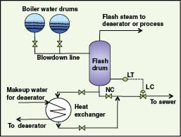
If the amount of blowdown water is significant, then in addition to flash steam recovery, sensible heat recovery from blowdown water will also be economical. Such a system consists of a flash tank and a heat exchanger to preheat deaerator makeup water as shown in Figure 1. It saves steam requirements in the deaerator, and also eliminates capital expenditure for cooling or quenching the blowdown water, or for cooling ponds. A predictive tool to estimate heat recovery from blowdown water was presented by Bahadori and Vuthaluru [ 5]; this requires boiler-water drum pressure, flash drum pressure and deaerator makeup water temperature.
| Table 1. Typical payback for a blowdown-water heat-recovery system | |||
| High-pressure condensate flowrate, ton/h | Typical flash separator (without demister) dimensions: diameter X height, m | Condensate cooler area, m2 | Payback, months |
| 16 | 2 X 4.07 | 33.16 | 1.4 |
| 12 | 1.74 X 3.8 | 24.87 | 1.5 |
| 8 | 1.42 X 3.48 | 16.58 | 1.9 |
| 4 | 1 X 3.06 | 8.29 | 3.2 |
For blowdown operations from 45 to 2.5 barg, typical estimated payback periods are shown in Table 1. The basis used includes: flash steam cost of $31/ton; condensate outlet temperature at the cooler is 40C; condensate-cooler overall heat-transfer coefficient, U = 1,136W/m2K, demineralized (DM) water (makeup water to deaerator) inlet and outlet temperatures are 30C and 50C respectively.
Steam condensate recovery. Reusing the hot condensate in the deaerator saves energy and reduces the need for treated boiler feedwater. The substantial savings in energy and purchased chemicals costs make building a complete condensate-return piping system very attractive. An additional benefit of condensate recovery is the reduction in the blowdown flowrate due to better boiler feedwater quality.
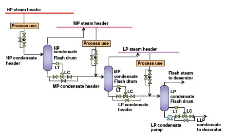
Due to the pressure and energy involved, high-pressure (HP)steam condensate should be recovered to the medium-pressure (MP) steam-condensate header; MP steam condensate should be recovered to the low-pressure (LP) steam-condensate header, and LP steam condensate should be recovered to the low-low pressure (LLP) steam condensate header (with a pressure close to that of the deaerator) using flash drums. Flash steam generation can be estimated with 0.6 to 4.3% accuracy, using the following equation and steam property spreadsheet, (freely available at www.x-eng.com; accessed in January 2012):
Flash steam, % = (sensible heat at high pressure − sensible heat at low pressure) × 100 ÷ latent heat at low pressure (1)
Recovered MP and LP flash steam can be used efficiently by mixing it in respective steam headers with sufficient superheat. LP flash steam can be directly used in the deaerator or can be upgraded using TVR or MVR for process use. This will also minimize the piping cost for the condensate header. Such a design is shown in Figure 2. A very detailed steam-condensate system-design review is available in Fleming [ 18].
Steam traps are mainly used to remove condensed steam from the system. If they are not properly maintained, they can malfunction, resulting in the loss of valuable steam to the condensate recovery network. Proper selection of steam traps and their maintenance is key to minimizing waste heat generation and steam loss. For a site without proper steam-trap monitoring and maintenance planning, it is not uncommon for about 25% of steam traps to leak [ 39]. Since a typical petroleum refinery can have a few thousand steam traps, the malfunction of 25% of these steam traps could result in huge energy losses if the traps blow to the atmosphere. And, if the steam traps blow to closed-loop condensate recovery, this can result in water hammering in the condensate recovery header.
Typical steam losses through blowing steam traps can be easily estimated based on the Cv (flow coefficient) method presented by Branan [ 11]. If the rated capacity of a steam trap is not available, then steam losses due to leaks or failures can be roughly estimated (assuming leakage size as a circular hole) using Grashof’s formula [ 12]:
Steam leak, lb/h = 0.70 × 0.0165 × 3,600 × A × P 0.97 (2)
Where 0.70 is the coefficient of discharge for the hole, 0.0165 is a constant in Grashof’s formula, A is the area of leaking hole in square inches and P is the pressure inside the steam line in psia.
Many efficient steam-trap monitoring systems are available from vendors. Use of suitable steam-trap monitoring systems can be very beneficial for minimizing waste-heat generation and also maintenance costs. Radle [ 37] highlighted the importance of intensive steam-trap management. McKay and Holland [ 31] presented methods to estimate energy savings from steam system losses. These methods can be used to estimate energy savings, and thus cost savings to justify improvements in steam trap systems.
Maximizing use of LP steam
Petroleum refineries usually have the capability to generate excess LP steam (< 5 kg/cm2g), mainly from steam turbine operations and also due to low temperature WHR. Any LP steam generation in excess of the demand may need to be released to the atmosphere. This will result in wasted energy. Petroleum refineries typically address this issue by switching some of the process steam-turbine drivers (generating LP steam) to electric motors, or by reducing the generation of LP steam from WHR.
The first method may reduce cogeneration benefits. Flash steam (near atmospheric pressure) is generally not recovered. This results in loss of recoverable energy. Sometimes flash steam is condensed using cooling water or air cooling. This will lead to a waste of latent heat of flash steam. Some attractive ways to use additional LP steam and atmospheric flash steam are outlined below.
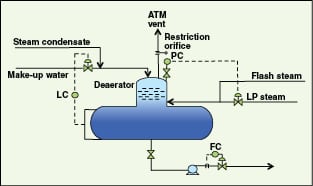
Optimization of the deaerator pressure. Generally, deaerators are designed to operate at very low pressures (~1.05 kg/cm2g) mainly to maximize cogeneration benefits. They use very low pressure steam (using pressure reduction of LP steam) and flash steam as the heating media. However, they are generally designed for relatively higher pressures (mechanical design pressures), such as 3.5 kg/cm2g. If makeup-water, flash-steam and condensate-recovery header pressures have safe operating margins for high pressure operation of the deaerator, one can increase the deaerator operating pressure to enable more usage of LP steam (Figure 3).
A higher operating pressure of the deaerator can result in the following benefits:
• Increased use of LP steam with minimum modification costs
• Potential to either totally eliminate or reduce the size of boiler feedwater (BFW) preheaters (used to prevent condensation of acid gases at the cold end side of economizers) at the inlet of economizers
• Elimination or minimization of the use of HP or MP steam used at these BFW preheaters, which can instead be used in a steam turbine to generate power
• If the boiler is not installed with an economizer, then there is no requirement for a BFW preheater. In this case, boiler fuel requirements will reduce in relation to additional heat absorption at the deaerator
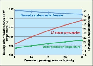
To further illustrate this concept, consider the following example. A deaerator (design pressure of 3.5 kg/cm2g) produces 240 ton/h of BFW, using makeup water at 80C, LP steam from steam turbines at 177C and 3.5 kg/cm2g. It can be seen from Figure 4 that as the operating pressure of the deaerator is increased, more LP steam is consumed and the BFW temperature increases.
Heating of combustion air with LP steam. LP steam can be used to preheat combustion air at boilers and fired heaters. This will reduce fuel consumption at the boiler or fired heater. In some cases, it also helps to prevent cold end corrosion in air-to-air pre-heaters. The typical payback period depends on available space in combustion air ducting, the cost of LP steam, and the proximity of steam and condensate headers.
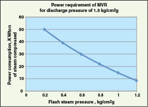
Upgrading LP or flash steam with MVR or TVR. LP steam or flash steam is generated by boiler steam-condensate flashing or leaks from steam turbines. It can be upgraded for process use via mechanical or thermal vapor recompression. Vapor recompression requires a mechanical compressor (in MVR) or steam jet ejector (in TVR) to increase the temperature of steam to make it usable for process duties. LP steam can be compressed to higher pressures using MVR. Figure 5 shows typical energy requirements for MVR. The coefficient of performance (COP; for a heat pump, this is the ratio of heat rejected at high temperature at the condenser to the energy input by the compressor) of MVR is very high — around 10–30 depending on the compression ratio. MVR is limited to applications where the compressor inlet pressure is above atmospheric and the compression ratio is less than 2.1 per stage (maximum value for single-stage centrifugal compressors used in the petrochemical industry [ 22], due to cost considerations).
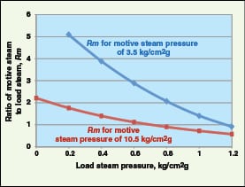
In TVR, motive steam at comparatively higher pressure is used to compress the LP flash steam using a steam ejector, and then delivered at an intermediate pressure. The following equation can be used to quickly estimate the approximate quantity of motive steam required for upgrading a given quantity of very low pressure steam [ 32].
Rm = 0.4 × e[4.6 × ln( PD/PL )/ln( PM/PL )]( 3)
Where Rm is the ratio of mass flowrate of motive steam to mass flowrate of load steam, PM is the absolute pressure of motive steam, PL is the absolute pressure of LP steam and PD is the target absolute pressure of discharge steam. This equation is empirical, applicable to motive saturated steam below 300 psig, and should be used for an Rm between 0.5 and 6.
Typical motive steam requirements of TVR for a discharge steam pressure of 1.5 kg/cm2g at various load steam pressures are shown in Figure 6. Steam recompression requires only 5–10% of the energy needed to raise an equivalent amount of steam in a boiler (OIT Tip sheet #11, January 2006, www1.eere.energy.gov/industry/bestpractices/pdfs/steam11_waste_steam.pdf).
Desalination. If sea water is readily available, LP or flash steam can be used to produce fresh water from sea water using various desalination technologies. Ophir and Gendel [ 34] discussed desalination by multi-effect flash vaporization to minimize energy consumption using 1.5–4.5 barg steam, generated from back-pressure steam turbines. They concluded that the technology using steam turbines (operating using 1.5–4.5 barg steam) and compressors (driven by steam turbine, for compressing flashed steam) reduced desalination costs by 13% compared to ejector technology. A thermal- and economic-performance study for low-temperature multi-effect evaporation desalination systems (LT-MEE), integrated with a steam-driven single-effect LiBr-H2O absorption heat pump, was presented by Wang and Lior [ 43]. A 60–78% water production gain was reported due to this integration as compared to stand-alone LT-MEE.
Applying heat pumps
Heat pumps to raise temperature
Heat pumps consume energy (external mechanical or thermal energy) to increase the temperature of waste heat and ultimately reduce the use of fuel. With low temperature lifts (difference between the evaporator and condenser temperatures) less than 100F, heat pumps can deliver heat for lower cost than the cost of fuel (U.S. Dept. of Energy, Industrial heat pumps for steam and fuel savings, http:// www1.eere.energy.gov/industry/bestpractices/pdfs/heatpump.pdf, Accessed in January 2012 ).
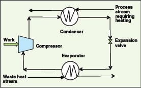
Mechanical heat pumps. Closed-cycle mechanical (vapor compression) heat pumps are generally applicable for waste heat temperatures less than 100C. A working fluid (typically ammonia, a hydrocarbon-based or another refrigerant) takes in waste heat and evaporates. The fluid is compressed and then condensed to give out heat at a higher temperature than the waste heat stream, and is finally returned to the evaporator via an expansion valve (Figure 7). Typical COP values for mechanical heat pumps are in the range of 3–8.
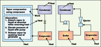
Absorption heat pumps.There are two types of vapor-absorption heat pumps. The first type (Type 1) is applicable for waste heat temperatures between about 100 and 200C. They transfer heat from a high-temperature heat source (waste heat) to bring a low-temperature process stream to an intermediate temperature. LiBr heat pumps can generate a temperature output of ~100C. Typical COP values for these heat pumps are 1.2–1.4.
New-generation heat pumps are under development to generate temperatures up to 250C for steam generation (HPC; www.heatpumpcentre.org/en/aboutheatpumps/heatpumpsinindustry, Accessed in January 2012). The absorption heat transformers (AHT) or temperature amplifier are Type 2 pumps, and operate in a cycle opposite to that of absorption heat pumps (Type 1). They take in waste heat at an intermediate temperature that is too low to be useable and upgrade some of it to a useful, higher temperature and cool the rest, thus acting as “heat splitters”. Up to about half the heat of the waste heat source can be upgraded. LiBr-based units can achieve temperature lifts up to 50C from waste heat sources at temperatures of 80 to 100C. Heat transformers can have output temperatures up to about 150C. Typical COP values for heat transformers are 0.3–0.5. An industrial application of the AHT system to obtain hot water was recently presented by Horuz and Kurt [ 24].
Applications. Both types of heat pumps (mechanical and absorption) can be used in distillation columns to save substantial energy (~33% reduction) for separating compounds with very close boiling points, such as propane/propylene and i -butane/ n -butane [ 14]. A low temperature lift gives a high COP and a large amount of heat upgraded per unit power. Open-loop mechanical (vapor compression) and thermal-compression heat pumps are used for flash steam recovery and desalination. An excellent review on advances in heat pump systems was recently presented by Chua and others [ 13]. Operating parameters and installation costs for various heat pumps are available in Ref. 8.
Heat pumps as chillers
Absorption heat pumps can also be used as chillers, which use thermal rather than mechanical energy for operation. Absorption chillers generally employ either LiBr or ammonia absorption in water. LiBr-water systems are limited to evaporation temperatures above freezing, because water is used as the refrigerant.
Advantages of the LiBr-water systems are that less equipment is needed, and operation can be at lower pressures. But this is also a drawback because pressures are below atmospheric, causing air infiltration into the system, which must be purged periodically. Due to corrosion problems, special inhibitors must be used in the LiBr-water system. NH3 absorption systems require high pressure distillation for regeneration of NH3, as water is also volatile. Refrigerant NH3 requires much higher pressures — about 1,100–2,100 kPa (absolute) in the condenser. The NH3-water system is capable of achieving evaporating temperatures below 0C.
The COP for absorption refrigeration (COPabs) is the ratio of refrigeration rate to heat input at the generator. Various chillers are compared in Table 2. More-detailed performance characteristics of refrigeration chillers are given in “ASHRAE Handbook-Refrigeration” [ 3]. NH3-H2O and LiBr-H2O chiller systems operate with comparable COPs.
The capital cost of absorption refrigerators rises sharply as the temperature of the heat source falls, making WHR uneconomical. Compared to mechanical chillers, absorption chillers have a low COP. Nonetheless, they can substantially reduce operating costs because they are energized by low-grade waste heat, while vapor compression chillers must be motor or engine driven. Absorption chillers are also more economical than steam jet refrigeration, which requires steam supply at relatively higher pressures of 7 kg/cm2g, makeup water and more cooling water. The waste heat source for an absorption chiller can be LP steam, or a hot gaseous or liquid stream. General operating principles of various chillers are shown in Figure 8. Typical operating requirements of various chillers are summarized in Table 2.
| Table 2. Typical operating requirements of absorption and mechanical chillers | ||||
| Type of Chiller | Main Driver | Typical Steam and Electrical Power Requirements | Typical Cooling Requirements [16] | Typical COP |
| Single stage absorption (LiBr system) | Very low pressure steam (~100 kPag) or hot water or hot stream > 93°C | Steam: 2.36–2.41 kg per kWh of refrigeration. Electrical power: 0.0028 –0.0114 kW/kWh of refrigeration [3] | 2.5 kW per kW of refrigeration | 0.6 –0.75 |
| Double stage absorption (LiBr system) | Relatively higher pressure steam (~800 kPag or more) or hot stream > 143°C | Steam: 1.25–1.29 kg per kWh of refrigeration. Electrical power: 0.0028–0.0114 kW/kWh of refrigeration [3] | 2.0 kW per kW of refrigeration | 1.19 –1.35 |
| Mechanical compression (propane) | Motor or engine driven compressor | Electrical power: 4.5 kW/kW of refrigeration [4] | 1.283–1.125 kW per kW of refrigeration | 4.5 |
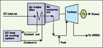
A typical application of absorption chillers is for heat recovery from fluegases (HRSG; heat recovery steam generator) to produce chilled water. HRSG recovers heat from gas-turbine (GT) exhaust gases. GTs consist mainly of one air compressor, one turbine and an air intake filter, as illustrated in Figure 9. Chilled water can be used to reduce the air inlet temperature at the air compressor of the GT. Air density at the air compressor inlet thereby increases, and hence mass flow increases through the air compressor. This is the most cost-effective method for increasing gross power output of the GT. It increases net incremental power output faster than incremental fuel consumption, resulting in improved overall fuel efficiency (reduced heat rate).
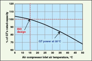
GT intake air through the air compressor can also be cooled by WHR using an ejector refrigeration system (EWRS). Application of an EWRS, utilizing about 30% of the total exhaust gas heat to pre-cool the air compressor intake air by 25°C, increases GT power output by 15–20% and the thermal efficiency by 2.0–3.5% [ 36]. The effect of an air compressor’s inlet-temperature reduction on power output of a typical GT is shown in Figure 10.
Use of chilled water (generated by using waste heat in a single-stage absorption chiller) at pre-condensers, can substantially reduce the fixed and operating costs of multi-stage steam ejector systems by condensing most of the suction vapor before entering the vacuum system.
Another application of absorption chillers is the recovery of the propane fraction of flare gas. Flaring in petroleum refineries occurs when waste refinery gas cannot be used in boilers or fired heater systems and has to be burned. The propane fraction of this waste stream represents a valuable coproduct that could be salvaged. One U.S. Dept. of Energy (DOE) sponsored project is on the development of an NH3 absorption unit running on waste heat to chill the gaseous waste stream from the reformer to about –30C to recover 200 barrels per day (bbl/d) of propane at a Denver refinery. This technology boosted profit by $900,000/yr, and paid for the unit in less than two years (www1.eere.energy.gov/industry/petroleum_refining/pdfs/ultramar.pdf, accessed in May 2011).
Fluegas heat recovery
High-temperature stack gases represent the major area of energy loss in combustion processes. The temperature of a fluegas depends on the temperature of fluid inside the tubes of the convection section of fired equipment, and the WHR method. Fluegas acid dew-point temperatures limit the possible heat recovery due to corrosion. For combustion of fuels with sulfur, it is widely accepted that 1–5% of SO2 generated in a combustion process will be converted into SO3 [ 19]. Based on SO3 content and H2O partial pressure, the sulfuric acid dew point can be easily calculated using the following equation [ 22]:
T dew (SO3) = 1,000/ [2.276 − 0.0294 ln( P H2O) − 0.0858 ln( P SO3)+ 0.0062 ln( P H2O P SO3)] (4)
Where T dew (SO3) is the sulfuric acid dew point in Kelvin, P H2O and P SO3 are partial pressures in mm Hg. A simple-to-use predictive tool for estimating the acid dew point, which accounts for fuel type, sulfur fraction in fuel and excess air, was recently presented by Bahadori [ 6]. So, for greater heat recovery from fluegas, changing the stack and its material of construction may also be required.
Heat reuse in the same process
Economizers for boilers. An economizer recovers waste heat from fluegases by heating BFW, and hence reduces boiler fuel requirements. Flue-gases are often rejected to the stack at 30 to 70°C higher than the temperature of the generated steam. Generally, boiler efficiency can be increased by ~ 1% for every 22°C reduction in fluegas temperature. By recovering waste heat, an economizer can often reduce fuel requirements by 5 to 10% and usually pay for itself in less than two years. Air preheat also reduces excess air. Economizers can be classified as condensing and non-condensing types for fluegas streams.
Non-condensing type: Their implementation requires a gas-to-liquid exchanger to be installed in the exhaust stack. They recover a major part of sensible heat from the fluegases as the heat is removed above the acid dew point. These economizers are applicable for boilers using fuel oil or gaseous fuel. They can be installed with bare tubes of carbon-steel construction or with glass coating, or finned tubes depending on the composition of fluegases and heat recovery targets.
Condensing type: They recover latent heat as well as sensible heat from fluegases and hence are able to increase boiler efficiency by up to 10%. They can be indirect- or direct-contact types. In an indirect-contact economizer, cold deaerator makeup water flows through a heat exchanger to recover fluegas sensible and latent heats. Condensed water from the fluegas will become acidic and need to be disposed of with proper treatment.
In direct-contact economizers, raw water is sprayed directly into the fluegas, to cool it below its acid dew point. These economizers typically use a packed bed for better contact of water with fluegases. The sprayed water and condensed water from the fluegas become hot and acidic, and the heat is recovered by another heat exchanger using cold deaerator makeup water. The economizer requires a pump to circulate hot water in a closed loop. A small stream of this water needs to be continuously disposed of (with proper treatment), and raw water needs to be added to compensate for the lost water. The temperature of fluegases can be reduced to 43–60C, depending on the amount of hydrogen, water in the fuel, amount of excess combustion air used and humidity of air.
An indirect-contact condensing type of economizer can heat deaerator feedwater to a higher temperature compared to the direct-contact condensing type. The possibility of corrosion from the acidic condensate is prevented by using more expensive materials like stainless steel and glass fiber for ducts and stacks, or by coating exposed metal surfaces with a resistant material, such as Teflon.
Condensation systems generally reduce particulate and SOx emissions. The penalty for firing with excess air decreases with reduction in fluegas temperature. Condensing economizers are difficult to implement (due to corrosion issues), if the boiler is sharing a flue stack with other fired equipment. Condensing economizers are applicable only if there is a requirement for hot water.
Economizers for fired heaters.If fluegas temperatures are very high (~700C), then adding a new coil to the convection section can increase furnace capacity and reduce fuel consumption by bringing the fluegas temperature to within 50–100C of the process-fluid inlet temperature at the inlet of the convection section [ 20].
Combustion air heating for boilers and fired heaters.An air pre-heater (APH) is a heat exchanger placed in the exhaust stack or ductwork that extracts a large portion of thermal energy in the fluegases and transfers it to the incoming combustion air. WHR from stack gases through air preheating proves to be more advantageous than other methods [ 15]. This practice also reduces required capacities of forced- and induced-draft fans because the combustion air quantity is reduced. The amount of energy saved through APH can be very large since stack temperatures can be reduced to below 180C (depending on the fluegas acid dew point). APHs require space, but energy savings can be as much as 20–30%, for the case of fired heaters. There are two types of air preheaters: recuperator and regenerator.
A recuperator is a fixed air-to-fluegas heat exchanger (without moving parts) placed in the furnace stack to preheat incoming air with hot fluegas. A regenerator is an insulated container filled with metal or ceramic shapes that can absorb and store relatively large amounts of thermal energy and then release that energy subsequently. Another design of a regenerator for continuous operation uses a continuously rotating wheel containing a metal or ceramic matrix. The fluegases and inlet stream (such as combustion air) pass through different parts of the wheel during its rotation to receive heat from the fluegases and release heat to the cold, inlet stream.
Installing APHs for smaller heaters (with absorbed duties of 7,000 to 10,000 kW and less) may not meet payback period requirements for most petroleum refineries. The payback period for installation of an economizer or APH depends mainly on the fluegas flowrate, stack temperature, annual operating hours and the need for hot water. An economizer or APH for water-tube boilers is typically not attractive for units operating under 10 kg/cm2g or below 20 ton/h of steam production, nor any size boiler that will normally run at reduced capacity. For industrial boilers, dual installation using both an economizer and an APH is rarely economical or installed.
Heat recovery using a heat-pipe.A heat pipe is a heat transfer element that can quickly transfer heat from one point to another with merits of high efficiency and compact size. Its heat transfer coefficient in the evaporator and condenser zones is 1,000–100,000 W/m2K, and its thermal resistance is 0.01–0.03 K/W, thus leading to a smaller area and mass of a given heat exchanger [ 42]. The mechanism of heat pipes is to employ evaporative heat transport to transfer thermal energy from one point to another by evaporation and condensation of a working fluid or coolant.
Because a heat pipe cannot function below the freezing point nor above the critical temperature of its working fluid, the selected working fluid must be within this range. In addition, vapor pressure, surface tension, contact angle and viscosity in the heat pipe must be considered in the selection of a working fluid [ 26]. Working fluids that can be used in low-temperature heat recovery include methanol (10–130C), flutec PP2 (10–160C), ethanol (0–130C), water (30–200C) and toluene (50–200C). Heat-pipes can be used as APHs in steam boilers, but their installations are limited, largely due to higher costs. Another major limitation of heat pipes is that they must be tuned to particular cooling conditions. The choice of pipe material, size and coolant all have an effect on the optimal temperatures in which heat-pipes work.
Gas turbine (GT) inlet air heater.GT inlet air (after air compression) can be heated with fluegases. Also, BFW can be preheated by installing an economizer in a heat recovery steam generator).
Heat reuse in other equipment
Fired heaters.Fluegas heat can be used for steam generation in the economizer, steam superheater and hot oil system. The pressure of steam generated will depend on the fluegas (hot stream) temperature. Steam pressure levels can be optimized with the available fluegas temperatures and based on the plant’s steam balance. Steam generation has the advantage that piping costs may be less due to proximity of steam headers in the plant; its disadvantage is that steam header pressures at a petroleum refinery, for example, are usually fixed, and hence, cannot maximize the amount of possible heat recovery. Generation of high pressure steam is preferred as it can be used for power generation. However, HP steam generation will lead to lower heat recovery from fluegas or another hot stream. A more costly and efficient system will use steam generation followed by air preheating.
In addition to steam generation, economizer coils can be added to heat water or intermediate heat transfer fluids. Saturated steam generated in the steam generators can be super heated by recovering heat from fluegases or hot streams. A hot oil circuit can be installed to supply heat to multiple locations in the process unit. A hot oil system can maximize the heat recovery, but requires additional capital investment.
Gas turbine. The exhaust gases from a GT (with and without duct firing) can be used for steam generation in HRSG at multiple pressure levels; or, it can be used to heat process streams. In some instances, the hot turbine exhaust is used as combustion air for a fired heater in the plant where a GT is located. Waste heat of HRSG exhaust can be used to produce chilled water using an absorption chiller or jet refrigeration to cool GT inlet air, and hence increase power output of the GT. It can also be used for organic Rankine or Kalina cycles (discussed in the next section) to produce power. The optimum choice of heat recovery method will depend on many factors, such as process heating requirements, available space, fluegas quantity, quality, refinery steam balance and payback criteria.
Heat recovery for power
All forms of energy, including work, can be fully converted into heat, but the converse is not generally true. As per the second law of thermodynamics, only a portion of the heat from a heat-work cycle — such as a steam power plant — can be converted to work. The remaining heat must be rejected as heat to a sink of lower temperature (atmosphere, for instance). For any process converting heat energy to mechanical energy, the Carnot efficiency is the theoretical maximum.
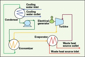
Organic Rankine cycle (ORC). This can work with waste heat streams in the lower-temperature range of 80 to 400°C [ 35] to generate electricity. An ORC engine is similar to a steam Rankine engine, except that it uses a lower-boiling-point organic fluid, instead of steam, as the working fluid. The working fluid is vaporized in the evaporator using waste heat, and the resulting high pressure vapor is expanded in a turbine to generate power. Low pressure vapor from the turbine is condensed in the condenser using cooling water or air. Finally, condensed working fluid is pumped to high pressure to the evaporator, to complete the cycle.
An economizer is generally added to reduce condenser cooling load and improve ORC efficiency, as illustrated in Figure 11. This cycle has the highest temperature at the evaporator and the lowest temperature at the condenser. In ORC, working fluids having higher vapor pressure than water are used. So, operating pressures and temperatures of ORC are lower than those of the Rankine cycle.
For working fluids with lower boiling points, the turbine inlet pressure can be higher and the circulating mass flow is lower (minimization of operating costs), thereby requiring a smaller size turbine. This results in no condensation during expansion in the turbines, which ensures longer life spans for turbine blades, and therefore super heating of the fluid is not required before expansion in the turbine.
Thermodynamic properties of working fluids affect the system efficiencies. An ORC working fluid should have a mainly positive or isentropic saturation vapor curve, high vapor density, high critical temperature and high heat stability. Liu and others [ 30] presented the effect of working fluids on ORC performance for WHR. Fluids used in ORC include propane, butanes, CFCs, freon, n -pentane, iso- pentane, hexane, ammonia, R245fa, octamethylcyclotetrasiloxane (D4) and many other proprietary fluids. Saleh and others [ 40] presented the performance of ORC for various working fluids for a maximum evaporator temperature of 100C. A screening study of several working fluids based on power production capability and equipment size requirements was presented by Lakew and Bolland [ 28]. It shows that R227ea gives the highest power for a heat-source temperature range of 80–160C and R245fa produces the highest in the range of 160–200C. Wei and others [ 44] studied the performance and optimization of ORC for WHR.
The extent of heat recovery can be calculated from exergy (available energy) of the waste heat stream. For estimating the electric power recovered, the following formula can be used:
Electrical power, kW = ηe × ηcarnot × WH = ηo × WH (5)
Where ηe is exergy efficiency; ηcarnot= Carnot efficiency = 1 – (cold source temperature, K / waste heat stream temperature, K, ηo = ORC efficiency and WH is the waste heat in kW. For a quick estimation of power, one ORC supplier, Cryostar (www.cryostar.com/web/heat-conversion.php, accessed in January 2012) indicates a value of 0.5 for ηe. Labrecque and Boulama [ 27] stated that, for waste heat to useful work conversion, exergy efficiency as high as 70% is conceivable. Bourji and others [ 10] proposed a correlation for approximately estimating ORC power generation from fluegas temperatures between 350 and 500F with ambient temperatures varying between 50 and 100F. They also estimated ORC power-generation potential for various refinery capacities and breakdown for various refinery units, using fluegas WHR.
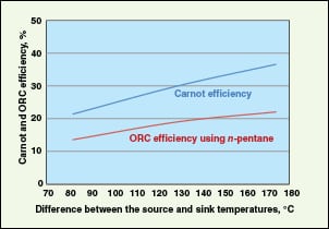
Using WHR, the efficiency of an ORC system ranges from 10% at 110°C to more than 22% at 270°C, depending on the temperature of the waste heat and working fluid (Freepower; www.freepower.co.uk/tech-overview.htm, accessed in January 2012). Drescher and others [ 17] reported ORC efficiencies as high as 28%, at a high waste-heat temperature of 350C. The highest thermal efficiency is achieved when the hot stream temperature is as high as possible, and the sink temperature is as low as possible. A typical comparison of Carnot and ORC efficiency is shown in Figure 12.
Exhaust heat of an ORC can be further utilized to drive absorption chillers. Quoilin and Lemart [ 35] presented a compilation of various ORC manufacturers and market evolution for various waste-heat source-temperature ranges.
Typical applications of ORC in petroleum refineries include recovery of waste heat from HRSG fluegases (known as organic bottoming cycle), distillation overhead streams and some hot product streams. Most fluegas treatment methods, such as those involving fluegas scrubbing, carbon capture and sequestration, require the fluegas stream to be cooled prior to its introduction into the treatment train. Thus, the addition of an ORC system can be of great benefit when used in combination with a downstream fluegas treatment system, and can help to improve the overall economics of fluegas treatment by generating additional power from waste heat in the fluegas stream.
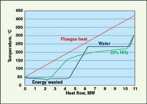
Kalina cycle.The Kalina cycle is a modified form of ORC using binary, mixed fluids instead of a single fluid. When a mixture of NH3 and water (typically 70% NH3) is used as the working fluid, the cycle is called “Kalina cycle”. This particular cycle works with waste-heat-stream inlet temperatures in the range of 250 to 1,000F and has the potential of efficiency gain over the ORCs. The main reason for improvement is that the boiling of the NH3-water mixture occurs over a range of temperatures, unlike steam (conventional Rankine cycle) or ORCs at a constant temperature. Hence, the amount of energy recovered from the hot stream is higher, as illustrated in Figure 13. Integration of a Kalina cycle in a combined heat and power plant for efficiency improvement was presented by Ogriseck [ 33]. ORC and Kalina cycles are similar when the heat source is condensing steam.
Other improvements to ORC and Kalina cycles. There are a few improvements to ORC under different stages of development and implementation. A cascading closed-loop ORC (CCLC; www.chpcenternw.org/NwChpDocs/stinger%20presentation.pdf, accessed in January 2012), patented by WOW Energy Inc., claims to recover waste heat over a wide temperature range with better efficiency. Biasi [ 9] reviewed the application of CCLC to increase gas turbine power and efficiency.
The Neogen cycle (www.sti.nasa.gov/tto/Spinoff2005/er_7.html, accessed in January 2012) is a variation of Kalina cycle, developed by NASA and Unitel Technologies to achieve higher efficiencies. A capital cost comparison of Rankine cycle, ORC and Kalina cycle [ 8] is given in Table 3.
| Table 3. Comparison of typical capital costs for various power cycles | ||
| Conversion Technology | Typical Sources of Waste Heat | Capital Cost |
| Traditional steam cycle | Exhaust from gas turbines, reciprocating engines, incinerators and furnaces | $1,100–1,400/kW |
| Kalina cycle | Gas turbine exhaust and boiler exhaust | $1,100–1,500/kW |
| Organic Rankine cycle | Gas turbine exhaust, boiler exhaust and heated water | $1,500–3,500/kW |
Plate and spiral heat exchangers
Compact-plate heat exchangers (CPHE) with their improved turbulence and counter-current flow, can achieve much higher heat-transfer efficiencies than traditional shell-and-tube heat exchangers, thereby increasing heat recovery and reducing the required heat-transfer area. Furthermore, the highly turbulent flow through the heat exchanger channels ensures the heat exchanger is kept clean, resulting in longer service time.
Case studies illustrating benefits of using CPHE in crude preheating, BFW preheating and steam generation are presented by Andersson [ 1]. CPHEs are generally applicable up to 450C and 40 barg. Such units can be designed to work with crossing temperatures (for example, the cold-side outlet temperature is higher than the hot-side outlet temperature) and with temperature approaches as close as 3°C [ 23]. Packinox is an example of a welded-type CPHE that is suitable for very high pressures and temperatures, such as 120 barg and 650C.
Plate heat exchangers with gaskets are used mainly for non-toxic and non-flammable substances at low temperatures and pressures. They can also be installed with fins.
Spiral heat exchangers exhibit better fouling resistance and higher heat transfer rates compared to shell-and-tube heat exchangers [ 2].
Final remarks
This paper provides a comprehensive review of several WHR methods and techniques applicable for process industries, especially petroleum refineries. It can be concluded from the review that considerable potential exists for recovering some of the wasted energy in the process industry, especially the petroleum refining industry, which can be used to improve energy efficiency. Economics of WHR vary from one unit to another and from site to site. A detailed economic study is required to decide the best WHR system(s) for a particular plant by considering many factors such as energy cost, plot size, capital cost, company payback criterion, operational, reliability, maintenance and process safety issues.
Edited by Dorothy Lozowski
Editor’s Note
There are two additional sections to this article on Minimizing Waste Heat Generation, and a Summary of Waste Heat Recovery Methods, which are available online at www.chemengonline.com.
References
1. Andersson E., Optimizing heat recovery with CPHEs, Petroleum Technology Quarterly, pp. 75–83, Q1, 2007.
2. Andersson E., Minimizing refinery costs using spiral heat exchangers, Petroleum Technology Quarterly, pp. 75-84, Q2, 2008.
3. “ASHRAE Handbook — Refrigeration (I-P) ed.”, American Society of Heating, Refrigerating and Air-Conditioning Engineers, Inc., 2010.
4. “ASHRAE Handbook – Fundamentals (SI) ed.”, American Society of Heating, Refrigerating and Air-Conditioning Engineers, Inc., 2009.
5. Bahadori A., Vuthaluru H. B., A method for estimation of recoverable heat from blowdown systems during steam generation, Energy, 35, pp. 3501–3507, 2010.
6. Bahadori A., Estimation of combustion fluegas acid dew point during heat recovery and efficiency gain, Applied Thermal Engineering, 31, pp. 1457–1462, 2011.
7. Bahadori A., Vuthaluru H. B., Estimation of energy conservation benefits in excess air controlled gas-fired systems, Fuel Processing Technology, 91, pp. 1198–1203, 2010.
8. BCS, Waste Heat Recovery: Technology and Opportunities in US industry, March 2008, www1.eere.energy.gov/industry/intensive processes/pdfs/waste_heat_recovery.pdf.
9. Biasi V.D., Cascade waste heat recovery for gas turbine power and efficiency, Gas Turbine World, pp. 22–25, September – October, 2008.
10. Bourji A., and others, Recover waste heat from fluegas, Chem. Eng., pp.37–40, September 2010.
11. Branan, C. R., “Rules of Thumb for Chemical Engineers – A Manual of Quick, Accurate Solutions to Everyday Process Engineering Problems”, 4th ed., Elsevier, 2005.
12. Capehart B. L., Turner W. C., Kennedy W. J., Guide To Energy Management, 5th edition, The Fairmont Press (2006).
13. Chua K.J., Chou S.K., Yang W.M., Advances in heat pump systems: A review, Applied Energy, 87, pp. 3611–3624, 2010.
14. Díez E., and others, Economic feasibility of heat pumps in distillation to reduce energy use, Applied Thermal Engineering, 29, pp. 1216–1223, 2009.
15. Doheim M. A., Sayed S. A., Hamed O. A., Energy analysis and waste heat recovery in a refinery, Energy, vol. 11. no. 7, pp. 691–696, 1986.
16. Doty S., Turner W.C., “Energy Management handbook”, 7th ed., The Fairmont Press Inc., 2009.
17. Drescher U., Bruggemann D., Fluid selection for the Organic Rankine Cycle in biomass power and heat plants, Applied Thermal Engineering, 27, pp. 223–228, 2007.
18. Fleming I., Optimizing steam systems: Part II, Petroleum Technology Quarterly, pp. 54–62, Q3, 2010.
19. Ganapathy V., Cold end corrosion: causes and cures, Hydrocarbon Proc., pp.57–59, January, 1989.
20. Garg A., How to boost the performance of fired heaters, Chem. Eng., pp. 239–244, November, 1989.
21. GPSA, “Engineering Data Book”, vol. 1, 12th ed., Gas Processors Suppliers Association, 2004.
22. Green D.W., Perry R.H., “Perry’s Chemical Engineers’ Handbook” 8th ed., McGraw- Hill, 2008.
23. Gunnarsson J., Sinclair Iain J.C., Alanis F., Compact Heat Exchangers: Improving heat recovery, Chem. Eng., pp. 44–47, February, 2009.
24. Horuz I., Kurt B., Absorption heat transformers and an industrial application, Renewable Energy, 35, pp. 2175–2181, 2010.
25. Kemp I.C., “Pinch Analysis and Process Integration”, 2nd ed., Elsevier Ltd., 2007.
26. Kutz M., “Mechanical Engine