Dispersion modeling of atmospheric releases from pressure-relief valves and other sources can be time-consuming. Follow this screening process to categorize which installations require detailed modeling and focus effort where it is most consequential
The safe design of atmospheric relief/venting systems is imperative in chemical and petrochemical facilities when pressure-relief systems are designed to release flammable or toxic materials directly to the atmosphere (as compared to a release to a flare or incinerator). Many facilities have the potential for atmospheric releases, either from existing installations or new designs that require simple discharge systems. Recent incidents and regulatory pressure have many facility designers asking the following questions:
• How many relief valves in the facility vent to the atmosphere?
• Are these relief valves safe?
• Can we ensure that the relief installations meet the requirements for RAGAGEP (recognized and generally accepted good engineering practices)?
To ensure that atmospheric discharges terminate at a “safe location,” as required by good engineering practices (for example, the American Society of Mechanical Engineers Boiler and Pressure Vessel Codes, section VIII UG-135(f)), engineers and designers should follow a systematic decision-making process. In this article, a safe location is an installation that meets the criteria in the American Petroleum Institute Standard 521 (Pressure-Relieving and Depressurizing Systems) [1] but may not meet more stringent requirements or environmental rules.
To determine the safety of atmospheric releases from pressure-relief valves, facilities can use industry-available modeling tools (such as DNV PHAST, BakerRisk SafeSite3G and so on) to perform dispersion modeling of the releases for consequence analysis. However, modeling every atmospheric release can become overwhelming and produce a large volume of data without adding value. Therefore, a more practical solution may be to apply a simple screening process that will categorize safe installations based on RAGAGEP practices. Following the screening process allows time and effort to be focused on those installations that fail simple screening and that require detailed modeling.
This article consolidates the simplified methods in API 521, and provides a decision-making process such that typical plant engineers with everyday tools can screen most atmospheric releases. The article can be used as the basis for screening the designed releases from atmospheric relief devices at new and existing facilities. In addition, this article provides qualitative, quantitative and semi-quantitative methods to screen the atmospheric release based on the hazardous properties of the discharged fluids, including non-flammable/combustible/toxic, flammable/combustible, and toxic materials.
Detailed dispersion modeling was performed to validate the results of the simplified equations presented in this article. While there are always rare circumstances that can occur, under the most common conditions for processing hydrocarbon streams, the methods in this article are conservative and can be used to screen atmospheric relief device installations. However, each installation is different and engineering judgement must be used to ensure that the specific installation meets all government and company requirements. There is no attempt here to create a methodology that will be applicable to all possible installations or discharge compositions. The user takes responsibility for how the methodologies proposed here are executed and interpreted. Environmental impacts and permit compliance is outside the scope of this article. However, these methods may help achieve compliance with the Risk Management Plan (RMP; U.S. Environmental Protection Agency) requirements in the U.S.
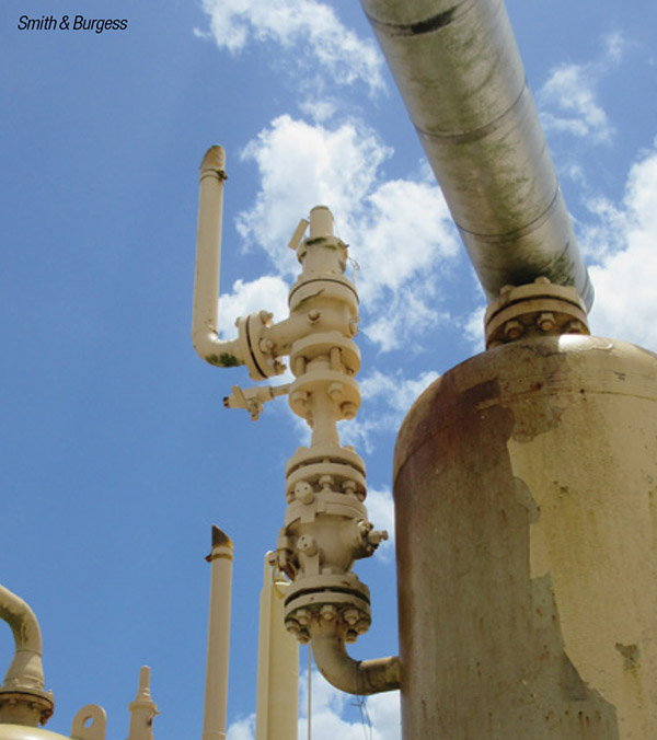
FIGURE 1. Designed releases of materials to the atmosphere can occur from pressure-relief valves, such as the one shown here, and other equipment
Designed atmospheric releases
Generally, in the chemical process industries (CPI), there are two major risks associated with atmospheric discharges: (1) the generation of a flammable or explosive mixture, and (2) the accumulation of toxic materials at a concentration level that may cause harm. Therefore, this article consolidates the simplified methods in API STD 521 to screen the atmospheric release based on the hazardous properties of the discharged fluids including flammability, combustibility, physical effects from non-flammable/non-toxic materials, and toxicity.
Methods and designs necessary to comply with environmental regulations are not discussed and must be independently verified.
The focus here is on designed releases from atmospheric pressure relief devices, rather than “accidental” releases from loss of containment. Consider the following two cases:
1. An amine regenerator overpressures and the relief device works as designed. This system is in a gas plant and the relief device’s final disposition is from an atmospheric collection system. The resulting vapor cloud results in H2S area monitors activating and the evacuation of all non-essential personnel from the site. The unit also shuts down.
2. A forklift driver delivers equipment near the amine regenerator and backs into piping, resulting in a leak from a control valve station. This leak creates a vapor cloud that activates H 2 S monitors. Consequently, all non-essential personnel from the site are evacuated and the unit shuts down.
Which case is worse? Arguably both cases could have been prevented with better engineering design, but in the first scenario the overpressure system functioned as designed and yet the facility was evacuated. This article will help engineers design installations such that the first scenario should not occur. The article focuses on designed releases (such as relief-device tail piping), as compared to facility siting concerns associated with loss of containment scenarios (such as vessel ruptures).
Atmospheric venting is designed into many petrochemical and refining facilities. Generally, designed or planned atmospheric releases come from several sources:
Control systems. Backpressure regulators, compressor stability control schemes and emergency shutdown devices can discharge to the atmosphere.
Pressure-relief devices. Pressure relief valves, rupture disks, and conservation vents can all have installations that discharge the effluent directly to the atmosphere.
Atmospheric collections systems. These systems can range from the collection of one or two relief devices into a single vent stack to systems as complex as flare systems terminating with a vent instead of a flare tip. Special considerations are required for the analysis of the vent, especially in global relief scenarios, as there is no designed means to burn the effluent.
Flare systems. Flare systems are designed to capture the effluent from the facility, remove entrained liquids, and burn the remaining vapor.
In addition to the listed vents, many other vent sources may occur in a facility. For example, in addition to venting from the discharge location, relief devices may vent from a broken bellows or pilot-operation system. Open pipe vents may occur (typically steam or other inert systems), but often there are process vents from normally closed isolation valves or through misaligned isolation valves. Low-pressure tank vents (pressure-vacuum vents, gooseneck vents, or otherwise) typically vent directly to atmosphere.
Often, these systems can be designed safely with proper consideration for the hazards of the fluid and for the design of the vent or flare. However, the focus of this article is on the direct discharge of atmospheric relief devices through the tail pipe (as opposed to venting through a broken bellows).
To evaluate whether the discharge of an atmospheric relief device occurs to a “safe location,” the engineers and designs should follow two steps:
Step 1. Determine the possible hazards of discharged fluids that are expected to release from the relief devices. This includes whether the fluid is flammable/combustible, toxic, or neither. The potential fluid discharges should be based on a thorough pressure-relief system analysis. Users are cautioned that relief devices located on equipment primarily containing no hazardous fluid might still have the potential for hazardous fluid discharge.
Step 2. Depending on the hazardous fluid type, the engineers/designers can apply the appropriate screening methods, as listed in the following sections.
Non-flammable, non-toxic fluid
Usually, these are the safest systems to discharge to atmosphere, since they rarely result in large-scale harm. When analyzing the location of the discharge, consider the following:
Effects on personnel. The effluent from a vent cannot be universally determined “safe” just because it doesn’t burn and is non-toxic. If the effluent stream could come into contact with personnel or equipment, the following criteria should be considered:
Impingement. The effluent stream contacting individuals or equipment could cause injury or damage. High-velocity fluid also has the potential to injure individuals who may be in the discharge path. When analyzing the impingement of an effluent on personnel, the engineer should analyze the immediate disposition of the fluid, as well as the subsequent movement of the fluid. The analysis should include nearby work areas, walkways, ladders and other areas designed for occupancy. Direct contact of a hot fluid, such as steam or water, could cause burns. Vapor liquid mixtures or those which may condense (for example, saturated steam) may result in the liquids “raining” down, even if the discharge is directed upwards.
Oxygen-deficient atmosphere. A large release of a simple asphyxiant into a building or confined area could dilute the oxygen in the atmosphere and thus make the area uninhabitable. Common industrial gases, like nitrogen, helium and argon, are classified as simple asphyxiants.
Emergency operations. The ability of operators to safely perform emergency procedures during a release should be considered. If a nearby isolation valve requires manual operation during a release, the designer needs to consider the effect of the release on the operator.
Noise. Depending on the characteristics of the vent and effluent, the noise generated from a release may be loud enough that plant personnel, even with hearing protection, may not be able to work in the area.
Public relations. Another consideration is the effect the release may have on the public. The designer needs to consider if a system will routinely release. Releases should be reviewed for the potential to form “clouds,” loud noises or odors. Any of these factors may interfere with operations or cause concern with the public.
Flammable/combustible fluids
These releases require more engineering review than non-flammable/non-toxic releases. The discharge of potentially flammable material to atmosphere is generally not preferred. However, the risks associated with atmospheric releases can be minimized by designing the system carefully. An extensive review of incident reports from various databases, including the Major Accident Reporting System (MARS), Major Hazard Incident Data Service (MHIDAS), and the National Fire Information Reporting System (NFIRS), concludes that incidents associated with atmospheric releases directly from relief devices, which are not part of a collection header or blowdown drum, are very rare. Therefore, with proper design that follows good engineering practices, facilities can ensure relief devices discharging flammable fluid to atmosphere are discharging to a “safe location.”
For systems with flammable or combustible fluids, or both, system designers should consider the following analysis (in addition to the criteria for the non-flammable/combustible and non-toxic fluids):
Fluid phases. For vapor releases, a release of flammable material begins at the process concentration. Then, as the fluid in the piping exits and begins to mix with the atmosphere, the concentration drops through the upper flammable limit (UFL), and at some point is diluted to below the lower flammable limit (LFL). After the concentration drops below the LFL, the effluent ceases to be a fire or explosion risk. All releases of potentially flammable material must be reviewed to ensure that the fluid has safely passed through the LFL before the “cloud” reaches a point of interest (such as an ignition source, grade, platform, equipment and so on).
Scenarios that could release flammable liquids or solids to atmosphere are generally not acceptable and require mitigation. The release case needs to be mitigated through one of the following mechanisms:
1. Dedicated safety instrumentation (compliant with ISA S-84 or other applicable standard) to the point that the potential for release is no longer credible
2. The relief system design must ensure that the liquid and solids are contained and are not vented (for example, a blowdown drum or tank) to the atmosphere.
At the time of writing this article, not all commercially available dispersion-modeling software accurately predicts the dispersion of liquids and solids. Unless engineers and plant designers can validate the model findings, the validity of the predicted flammable concentrations for liquid and solid releases may not be useful.
Installation. Relief-device exit piping should be pointed vertically upward. With proper design of the device, discharge configuration has historically been a safe means of disposing flammable vapors.
Semi-quantitative analysis. The primary concern when analyzing flammable atmospheric releases is the potential to form a flammable cloud near ignition sources or workers. API STD 521 7th edition, section 5.8 provides a series of guidelines to determine if a relief device discharging flammable vapor to atmosphere is acceptable based on the “jet” momentum and velocity mixing effects of the discharge. The greater the exit velocity, the more turbulently the material mixes with air. This results in the concentration of the released material quickly decreasing to below the LFL. Even in releases where there are high winds present, higher velocities from vertically oriented vents are directed more vertically than horizontally.
The following is a semi-quantitative method (in accordance with API STD 521 7th edition in§5.8) to determine if a release is to a “safe location.” To be considered safe, an affirmative response to all of the following is required:
• The molecular weight (MW) of the fluid is less than 80 g/mol for a hydrocarbon release (additional information below in Note 1)
• The exit velocity is greater than 100 ft/s (additional information below in Note 2)
• The ratio of the exit velocity to wind speed is greater than 10
• There is no equipment or work areas at or above the release point horizontally for 50 ft
• The relief/jet temperatures are close to or above the expected atmospheric temperatures
• The qualitative considerations from the non-flammable/combustible and non-toxic fluids section have been reviewed
Note 1. For hydrocarbon releases with a MW greater than approximately 100 g/mol, there is an increasing chance for condensation. Relief streams continuing with other fluids may condense as well. Depending on the velocities and concentration of the fluid at the point which the temperature drops, an explosive atmosphere may be formed. (More information on this topic can be found in Refs. 2 and 3.
Note 2. Relief devices are not expected to flow at rated capacity all of the time. The guidance in Section 5.8 of API STD 521 7th edition says to consider that relief devices close at approximately 25% of the rated capacity. Thus, a designer may need to consider a range of flowrates for an installation based on the results of the relief-systems analysis.
If the installation does not meet all the listed criteria above, consider the quantitative analysis procedure in the following section.
Quantitative analysis
This section presents the simplified analysis presented in API STD 521 7th edition Figures 8 and 9. The figures are condensed into a simple equation to calculate the horizontal downwind distance that the flammable vapor may travel prior to dilution below LFL concentration. For an atmospheric relief device to be considered to discharge to a “safe location,” no potential ignition source should be located within that radius at or above the release elevation.
Figure 2 depicts an atmospheric release of a flammable vapor stream as the concentration of effluent starts above the UFL, is then within the flammability limits, and finally drops below the LFL. The vertical and horizontal distances to below the LFL are based on API STD 521 7th edition Figure 8 and Figure 9, respectively.
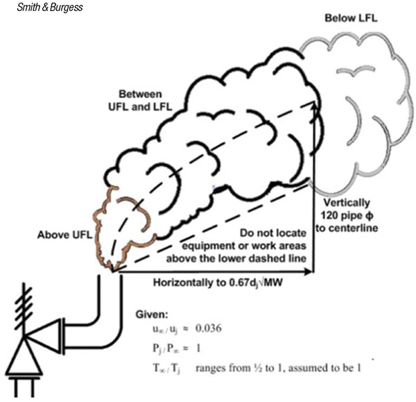
FIGURE 2. After the atmospheric release of a vapor-phase material, the downwind distance that the material will travel at concentrations between its UFL and LFL must be determined
The data shown in API STD 521 7th edition Figure 9 were cubic feet to develop an equation to calculate horizontal downwind distance to LFL. The maximum downwind horizontal distance from jet exit to lean-flammability concentration limit for petroleum gases can be expressed as follows:
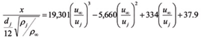 (1)
(1)
Where:
x is the horizontal distance downwind to the LFL for a hydrocarbon release, ft
dj is the inside diameter of the jet release exit, in.
ρj is the density of the fluid just inside the tip exit, lb/ft³
ρ∞ is the density of the ambient air, lb/ft³
uj is the fluid jet exit velocity, ft/s
u∞ is the wind speed, ft/s
For an ideal gas,
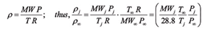 (2)
(2)
Where:
MWj is the molecular weight of the jet release fluid
MW∞ is the molecular weight of the atmosphere, 28.8 g/mol
Pj is the pressure of the fluid just inside the tip exit, which is typically atmospheric pressure in the case of a pipe exit, psia
P∞ is the pressure of the ambient air / atmosphere, psia
Tj is the fluid jet exit temperature,°R
T∞ is the temperature of the ambient air / atmosphere,°R
The following is the result of substituting Equation (2) into Equation (1) and solving for the distance downwind to the lower flammability limit:
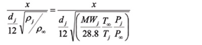 (3)
(3)
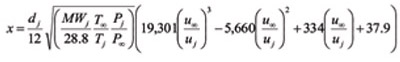 (4)
(4)
With the following conservative assumptions, Equation (4) can be further simplified:
u∞ / uj ≈ 0.036, the maximum downwind extents of the LFL
Pj / P∞ ≈ 1, the pressure at the maximum vent velocity is near atmospheric pressure
T∞ / Tj ranges from 0.5 to 1, and is assumed to be 1. For an atmospheric temperature of 70°F, the release temperature would be limited between 70°F and 600°F or less for this assumption
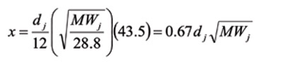 (5)
(5)
Engineers and designers can use Equation (5) to quickly calculate horizontal downwind distance to LFL concentration.
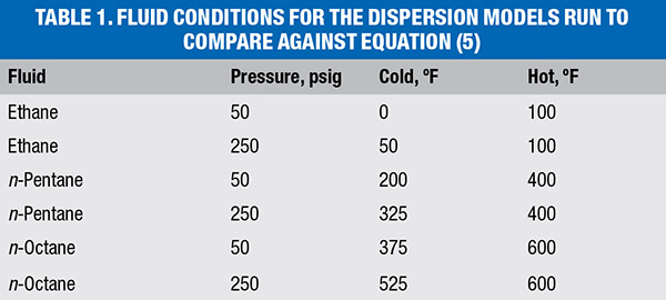
Two hundred sixteen unique dispersion models were performed in DNV PHAST to validate Equation (5).
Each dispersion model was run with three different weather conditions. The conditions for the different releases are shown in Table 2. Each of the cases in Table 2 were run for Crosby 1½G3, 4M6 and 6Q8 relief devices. The discharge point has the same pipe diameter as the relief-device outlet. The wind speeds used were 3.5 ft/s, 5 ft/s and 10 ft/s, all with an atmospheric stability class of D. The cases were run at the full capacity of the relief device (as determined by PHAST) and 25% of the rated relief device capacity.
For each of the cases reviewed, Equation (5) predicted the extent of the flammable zone to be 1.3 to 3.0 times farther than the horizontal distance predicted by the PHAST modeling. Also, for the smaller-diameter vents with lower-MW fluids, Equation (5) tended to overpredict the horizontal distance by 1.3 times more than the dispersion modeling. For the larger vents with higher-MW fluids, Equation (5) tended to overpredict the horizontal distance by as much as three times compared to the dispersion modeling.
The dispersion modeling to test Equation (5) showed that as much as 1/6 to 1/3 of the cloud height may be between the cloud centerline and the lowest point where the LFL is present. As such, detailed dispersion modeling should be completed if there is equipment above the discharge location within the LFL horizontal distance predicted by either Equation (4) or Equation (5).
Note that this method does not consider the effects of condensation of the effluent stream, which must be considered by the relief system engineer/designer (see Note 2 in the previous section).
Potential for ignition. API STD 521 requires the system designer to review the potential effects of thermal radiation on workers if the release stream is ignited. This is the case even when there is no potential ignition source within the flammable cloud. Ignition of the effluent stream may still occur (for example, because of static electricity, lighting, autoignition and so on) and the impacts of thermal radiation exposure should be considered. Some facilities install the ability to inject emergency steam into the tail pipes of relief devices to snuff out flames should the effluent catch fire.
Toxic fluids
The information in API 521, and thus in this analysis, is based on the characteristics of hydrocarbon vapors. Thus, when effluent streams deviate from this assumption, the system designer is cautioned to use good engineering judgement.
In addition to the previously identified considerations, evaluation of toxic fluid release should consider the followings analysis:
Vapor-phase releases. Releasing toxic vapor to atmosphere might be safe if the concentration of the toxic component in the release decreases to below acceptable threshold before the effluent comes in contact with personnel.
Liquid-phase releases. Releasing toxic, volatile liquids directly to the atmosphere should be avoided. The discharge of liquids that are non-volatile (such as caustic) may be acceptable. However, acceptance criteria for these releases is out of the scope of this article.
Concentration of toxics in release streams. The diffusion and dilution effects apply to all constituents of the effluent. The guidance in API STD 521 7th edition§5.8 indicates that for typical hydrocarbon streams, the concentration might be diluted to below 5.0 vol.% for methane and 1.2 vol.% for hexane on a volume basis before losing the jet momentum. Therefore, if the toxic fluid can be assumed to have similar characteristics to light hydrocarbon, the concentration of toxic components may be diluted anywhere from 1/20 to 1/80 of the original concentration, due to the effects of jet mixing.
Hence, Equation (6) may be used to estimate the maximum concentration of a toxic compound in an effluent stream that meets all the criteria in the list given in the “semi-quantitative analysis” section. If there is the potential for personnel in the immediate vicinity of the area of release plume (while it is still a jet), detailed dispersion modeling may be required.
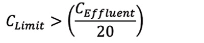 (6)
(6)
Where:
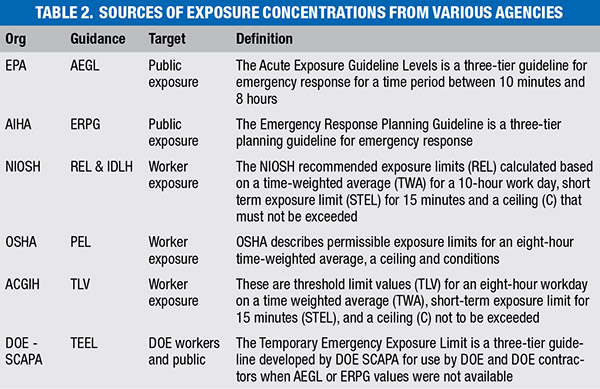
CLimit = the highest concentration that meets the risk acceptance for the toxic material, ppm (see Table 2)
CEffluent = the concentration of the toxic material in the effluent stream, ppm
Determining an acceptable lower concentration (CLimit) can be difficult, but there are a variety of sources that offer guidance (see Table 2). The list in Table 2 is only provided for guidance. It is the responsibility of the system designer to ensure that all regulatory and site requirements for releases are met.
In summary, if systems meet the qualitative criteria listed and if the concentration limits satisfy Equation (6), the maximum toxic concentration to which workers may be exposed should be below the concentration that meets the risk-acceptance criteria. For example, if the relief-device toxic vapor release has a H2S concentration of 2,000 ppm (or less), then the peak exposure will be below the IDLH (immediate danger to life and health) concentration of 100 ppm for locations where personnel are present. Corporate or regulatory requirements may be different than this example for H2S.
This screening method has limited applicability for streams that contain high concentrations of toxic materials or for facilities that handle extremely toxic chemicals. Users are cautioned if using this screening method for materials that do not have characteristics similar to light hydrocarbons, because the jet-mixing effect of those streams might be different. For those systems, detailed dispersion modeling might be needed
Concluding remarks
The methods presented here are simplified and can be readily used by system designers to screen atmospheric relief-device installations to meet the “safe location” criteria as presented in API STD 521. Following the methods outlined in this article, a system designer should be able to document each of the following questions:
• Do these relief valves discharge to a “safe location”?
• Can we show that the discharge location meets good engineering practices?
• Which relief-device systems require additional analysis (dispersion modeling)?
For each atmospheric discharge, if the provided systematic decision-making process is followed and documented, atmospheric discharges can be shown to vent to a “safe location,” as required by good engineering practice. Detailed dispersion modeling was performed to validate the results of the simplified equations presented here. While there are always rare circumstances that can occur, under the most common conditions that hydrocarbon streams are processed, the methods discussed here are conservative and can be used to screen atmospheric relief-device installations.
Edited by Scott Jenkins
Disclaimers
All information presented in this article is meant to be used by a qualified and experienced engineer or relief system designer. The content of this article is general in nature and based on the guidance provided in API STD 521. It is up to the end user to verify the safety and/or legality of any installations. With any predictive model, there may be variations between the results predicted and the results that occur from any given incident. For energetic or extremely toxic substances, or those where the concentrations predicted are close to the acceptable limits and risks, additional analysis should be performed. The user is cautioned to design a system that has a safety margin that allows for the inherent errors in this type of estimation. As with other aspects of these evaluations, good engineering judgment and knowledge of the specific installations must be considered.
This article is offered for general informational purposes only. Readers should consult with a qualified profession regarding their specific projects or work. The authors disclaim any and all liability arising from or concerning the analysis contained in this article.
References
1. API Standard 521, “Pressure-relieving and Depressuring Systems,” American Petroleum Institute, 7th ed., 2020.
2. Gant, S. and others. Generation of Flammable Mists from High Flashpoint Fluids: Literature Review, Health and Safety Laboratory (HSE) Symposium Series, number 158, 2013.
3. Burgoyne, J.H., The Flammability of Mists and Sprays, IChemE Second Symposium on Process Hazards, 1963.
3. “Documentation for Immediately Dangerous To Life or Health Concentrations (IDLHs),” Centers for Disease Control and Prevention. Centers for, May 1994. 12 November 2013, www.cdc.gov.
4. Frank, Michael V. “Choosing Safety: A Guide to Using Probabilistic Risk Assessment and Decision Analysis in Complex, High-consequence Systems.” Washington, D.C., Resources for the Future, 2008.
5. Loudon, D. E. “Requirements for Safe Discharge of Hydrocarbons to Atmosphere,” 28th Mid-year Meeting of the American Petroleum Institute’s Division of Refining. Philadelphia, Pa. 15 May 1963. Speech.
6. Centers for Disease Control and Prevention (CDC), www.cdc.gov, 04 October 2013.
7. Turner, D. Bruce. Workbook of Atmospheric Dispersion Estimates, U.S. Department of Health, Education, and Welfare, 1970.
8. Weber, A. H. “Atmospheric Dispersion Parameters in Gaussian Plume Modeling,” U.S. Environmental Protection Agency, 1976.
9. DeVaull, George E., John A. King, Ronald J. Lantzy, and David J. Fontaine. “Understanding Atmospheric Dispersion of Accidental Releases,” New York: American Institute of Chemical Engineers, 1995.
Authors
Dustin Smith is a co-founder and principal consultant at Smith & Burgess (7600 W. Tidwell Rd., suite 600, Houston, TX 77040; Email: [email protected]; Phone: 1-713-802-2647; www.smithburgess.com) a process safety consulting firm headquartered in Houston. He has extensive experience helping facilities that process highly hazardous chemicals maintain compliance with the OSHA process safety management (PSM) standard. Smith has over 25 years of experience in relief and flare system designs and PSM compliance. Smith received a B.S.Ch.E. from Texas A&M University. Smith is a licensed engineer in the state of Texas.
John Burgess is a co-founder and principal consultant Smith & Burgess (same address as above). He has extensive experience providing assistance to facilities that process highly hazardous chemicals in maintaining compliance with the OSHA process safety management (PSM) standard. Burgess has over 25 years of experience in relief and flare system designs and PSM compliance. Burgess received a B.S.Ch.E. degree from Texas Tech University and a M.S. from University of Missouri. Burgess is a licensed engineer in the state of Texas.
Thuc Ngo is a lead consultant at Smith & Burgess (same address as above). She has over 10 years of experience working on over 100 projects in relief & flare system designs. She received B.S.Ch.E. and M.S.Ch.E. degrees from the University of Houston. Ngo is a licensed engineer in the state of Texas.