I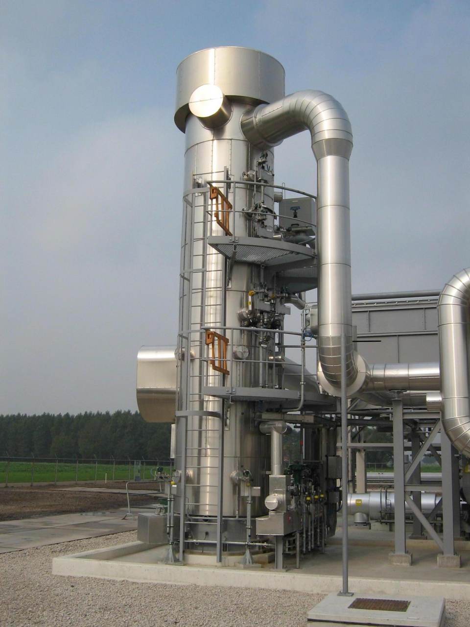 n pressure vessel design, use this procedure for determining the individual permissible flange loads for joints between pressure vessel nozzles and connected pipework
At the initial design stage of pressure vessels with nozzles that are provided with standard flanges according to ASME B16.5 or ASME B16.47 Series A, the layout (routing) of piping connecting to the nozzles is still unknown or not completed. As a result, the loads (piping reactions) exerted by the connecting pipework are also unknown. The nozzle loads are essential in completing the pressure vessel design. In order to achieve a prudent and reliable finalization of the pressure vessel design, a conservative estimate of the magnitude of such nozzle loads should be made. It has been found in practice that the flanged joints between pressure vessel nozzles and connected pipework can be considered as the weakest link in the system.
This new insight has been obtained from numerous practical situations that occur in the temperature domain between –30 and 250°C. Therefore, it has been chosen to primarily base the nozzle loads on the permissible flange load. In order to serve engineers in their design effort, an approximate method is designed to err on the safe side. The procedure for determining the individual permissible flange loads is described below. These loads, together with internal pressure, should be considered for evaluation of the local stresses as per applicable design code. If local stresses are within acceptable limits, then the design of the pressure vessel can be considered as being completed.
Determination of permissible individual flange loads
For the flanged connection, the condition of Equation (1) must be met:
![]()
Where:
Pd = Internal design pressure, MPa
Dg = Effective sealing diameter, mm
Dbc = Bolt circle diameter, mm
F and M = Local loads (see Figure 1)
![]()
Kf = the Koves factor, which is in fact a moment correction factor that smooths the effect of bending moments
Note that the greater the torsional resistance (relative to the bending resistance), the less the induced circumferential bending stress and corresponding flange rotation as a result of the external moment.
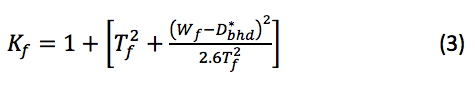
The Koves factor can be expressed as:
![]()
Where:
![]()
E = Youngs modulus or modulus of elasticity, MPa
ν = Poisson’s ratio, unitless
I = Moment of inertia of flange cross section or second moment of area of flange cross section, mm4
J = Polar moment of inertia of flange cross-section, mm4
The polar moment of inertia, J, is a quantity used to predict an object’s ability to resist torsion, in objects (or segments of objects) with an invariant circular cross section and no significant warping or out-of-plane deformation.
In the field of structural engineering, the second moment of area of the cross-section of a beam is an important property used in the calculation of the beam’s deflection and the calculation of stress caused by a moment applied to the beam.
The expression for Kf, Equation (2), can be written as:
Where:
Dbhd = Bolt hole diameter, mm
![]()
Dif = Flange I.D., mm
Dof = Flange O.D., mm
Tf = Flange thickness, mm
Wf = 0.5(Dof – Dif) = Flange width, mm
Permissible individual flange loads
Equations (4) and (5) give the piping reactions assumed to be induced from external pipework, which shall be taken into account in the mechanical design of mechanical static equipment in addition to internal pressure.
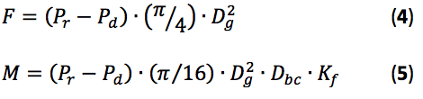
Where:
Pd = Internal design pressure, MPa
Pr = Rated pressure (ASME B16.5 or ASME B16.47), MPa
The local loads F (N) and M (N.mm) are the local loads to be introduced with directions according to Figure 1. After determination of the reference loads F and M, the following load cases, as indicated in Table 1, should be considered in the stress analysis of the relevant nozzles.
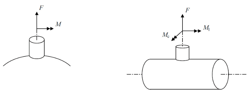
Figure 1. These figure show the local loads, F and M, and their directions
Table 1. Load cases to be considered for stress analysis
|
Load case |
Nozzle on cylindrical shell |
Nozzle on spherical part of head |
|
1 |
Pd + F |
Pd + F |
|
2 |
Pd + Mc with Mc = M |
Pd + M |
|
3 |
Pd + Ml with Ml = M |
– |
Note that shear stresses caused by transverse force and the torsional moment may be left out of consideration at the nozzle-shell intersection, since their contribution will not amount to more than 0.15 times the allowable stress.
Remark
In almost all internationally recognized design codes or standards, rules have been laid down for the assessment of nozzle loads. In most cases, reference is also made to sources from the literature on this topic.
Finally, if the final piping design is completed and the piping reactions are known, the following inequality, or load fraction rule, should be satisfied:
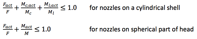
Where:
Fact = Actual radial force derived from pipe stress analysis, N
F = Individual allowable radial force, N
Mc;act = Actual circumferential moment derived from pipe stress analysis, N.mm
Mc = M = Individual allowable circumferential moment, N.mm
Ml;act = Actual longitudinal moment derived from pipe stress analysis, N.mm
Ml = M = Individual allowable longitudinal moment, N.mm
M = Allowable individual moment, N.mm
If the sum of the load fractions exceeds 1.0, the piping reactions may cause excessive stresses in the nozzle-shell junction. This calls for either a more rigorous analysis or a redesign of the nozzle or piping.
If the load fraction rule is met, then it might be considered that the nozzle load-induced shell stresses are within acceptable limits. Thus, it has been proven that the concerned flanged nozzle has adequate load capacity to withstand the internal pressure plus piping reactions without overloading the flange joint and to overstress of the nozzle-shell junction.
For those who are interested in the background of the introduced Koves factor, please see Ref. 1.
Example calculation
A pressure vessel is equipped with flanged nozzles placed on both the cylindrical shell and on the curved part of the torispherical head. The DN 300 (NPS 12 in.) type welding neck flanges class 300 are compliant with ASME B16.5 and are made of ASTM A105 material. The gaskets used are of the spiral-wound type according to ASME B16.20. The nozzle neck has a nominal thickness of 9.53 mm (STD).
The internal design pressure of the pressure vessel is 31.5 bars and the design temperature is 200°C. The rated pressure of the class 300 flange at 200°C is 43.8 bars.
Table 2 summarizes the specific data needed for the calculation.
Table2. Data for example calculation
|
Pd, MPa |
Pr, MPa |
Dg, mm |
Dbhd, mm |
Dof, mm |
Dif, mm |
Dbc, mm |
Tf, mm |
|
|
3.15 |
4.38 |
357.5 |
31.75 |
520 |
304.84 |
450.8 |
49.3 |
|
From Equation (3), we find a value for the Koves factor, Kf:
Wf = 0.5(520 – 304.84) = 107.58 mm
D*bhd = max [31.75 (1 – 304.84/1,000) ; 0.5 × 31.75] = max[22.07 ; 15.87] 22.07 mm
Kf = 1 + [49.32 + (107.58 – 22.07)2] /(2.6 x 49.32) = 2.542
Permissible individual flange loads are found from Equations (4) and (5):
F = (4.38 – 3.15) × (3.14159/4) × (357.5)2 = 123,466 N = 123.466 kN
M = (4.38 – 3.15) × (3.14159/16) × (357.5)2 × 450.8 × 2.542 = 35,370,935 N.mm = 35.3 kNm
In this example, the stress analysis of the nozzles for the various load cases plus application of the so-called load fraction rule have been left out of consideration.♦
Edited by Gerald Ondrey
Reference
- Dekker, C.J. and Brink, H.J., External Flange loads and ‘Koves’-method, Int. Journal Pressure Vessels and Piping, vol. 79, pp. 145–155, 2002.
Author
 Walther Stikvoort (Address: Wagnerlaan 37, 9402 SH Assen, the Netherlands; Email: [email protected]) is a renowned principal mechanical & structural integrity consultant, who has spent about 50 years in the design and design verification of pressure vessels and piping to recognized key design codes and also has significant experience in fitness-for-service engineering critical assessment (ECA) according to common FFS procedures. He has demonstrated his expertise in several key roles, such as expertise holder static equipment engineering (Authority Level TA-1) at NAM (a joint venture of Shell and ExxonMobil) (18 years) and as manager mechanical engineering at Kellogg Continental (15 years). Moreover he worked for NRG as a senior consultant asset integrity (7 years) and for GLT PLUS (Jacobs) as a principal consultant mechanical integrity (6 years). He developed numerous engineering standards and practices focused on improving asset integrity and involved in the development and lecturing of training courses and seminars for the pressure equipment community. As author and co-author various papers and articles have been published in recognized international journals, engineering textbooks and technical magazines. Stikvoort graduated from the Higher Institute of Technology (the Hague), where he studied mechanical engineering.