Hydrogen Production via Methane Pyrolysis: An Overview of ‘Turquoise’ H2
‘Turquoise’ hydrogen processes generate H2 without releasing CO2. Presented here are the opportunities and challenges for producing hydrogen by methane pyrolysis

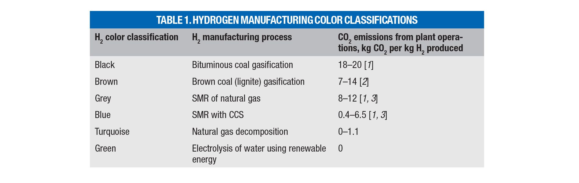
Hydrogen-producing processes are classified using a color scheme according to their carbon footprint (Table 1; [1–3]). So-called “turquoise hydrogen” is produced by methane decomposition, which encompasses the following: thermal breakdown of molecular bonds (pyrolysis); non-thermal breakdown using non-thermal plasma (plasmalysis); radiation (photolysis); and chemical splitting (chemolysis) through halogenation or NiCl2 redox reactions [4, 5]. Adjacent H2-producing processes involve pyrolysis of plastic waste, paper and biomass, methane coupling into acetylene, dry methane reforming, hydrogen sulfide splitting and others.
This article discusses the thermodynamics, process configurations and technical challenges associated with turquoise hydrogen production. A companion piece to this article (see Commercial Progress on Turquoise Hydrogen) covers the commercial development of turquoise H2, along with the progress of companies and research organizations that are pushing the technology ahead.
At the present time, turquoise hydrogen is a competitor to incumbent grey hydrogen, produced by steam methane reforming (SMR), and to blue hydrogen, produced by SMR with added carbon capture and storage (SMR-CCS). Compared to SMR, methane pyrolysis consumes twice as much feed to produce the same quantity of hydrogen. However, it does not produce direct CO2 emissions, and offers energy savings, as well as potential revenues from the sale of carbon co-product.

Methane pyrolysis
Methane can be viewed as a hydrogen carrier, like ammonia, rather than as a fuel. The methane pyrolysis (MP) reaction (Equation (1)), also called methane cracking, splitting or thermolysis, breaks methane molecules directly into elemental hydrogen and carbon at elevated temperatures, typically at 600–1,200ºC:
CH4(g) ––> 2H2(g) + C(s)
∆RH0 = 74.85 kJ/mol CH4
∆RH1,000ºC = 91.7 kJ/mol CH4 (1)
The MP reaction is endothermic and requires 37.4 kJ/mol H2 at standard conditions, in contrast to th286 kJ/mol H2 needed to produce green H2 by water splitting through electrolysis or thermolysis. It also compares favorably to the 63 kJ/mol H2 required by the SMR reaction combined with the water-gas shift reaction and steam generation for the reformer.
If all H2 produced is combusted, the overall cycle can be viewed as burning off hydrogen only while leaving carbon intact. Combustion of produced H2 yields 484 kJ/mol CH4, which provides 60% of the low heating value of methane (802 kJ/mol CH4), where carbon is fully oxidized to CO2.
The MP process can thermally sustain itself since only 15–25% of available H2 combustion heat is needed to provide the required heat for the reaction. The remaining 75–85% of H2 produced can be exported or used onsite.
Methane conversion yield is promoted by low pressures and higher temperatures, in accordance with La Chatelier’s principle. MP reactors are maintained above atmospheric pressure to prevent in-leakage of air anywhere in the process, to minimize reactor size and to speed the reaction.
As for kinetics, the reaction becomes spontaneous at approximately 550ºC and attains chemical equilibrium at higher temperatures (1,300ºC+) and higher pressures (>1 atm). Reaction rates at lower temperatures are relatively slow, so the overall conversion is kinetically limited. For this reason, considerable research efforts have been invested into developing catalysts capable of speeding up the reaction at lower temperatures.
For initial reactor sizing and determining the overall CH4 conversion, the MP reaction rate, r, can be expressed through a simple first-order kinetic equation:
r = –d[CH4]/dt = k[CH4] (2)
where the reaction rate constant, k, is given by the Arrhenius equation.
k = A exp (–Ea/RT)×[CH4] (3)
The pre-exponential factor A and the activation energy Ea are determined experimentally and can be found in literature for specific reactor configurations. For example, Becker and others [6] present a compilation of A and Ea values for various reactor types.
Equation (1) does not account for reactive species, such as acetylene, ethylene, ethane and higher hydrocarbons, along with CO2, H2O and mercaptans that may be present in natural gas. To account for these species, schemes involving simultaneous reactions were developed (see the online version of this article at www.chemengonline.com).
Natural gas (NG), the main source of methane, is widely available through the existing 3-million-mile long pipeline infrastructure in the U.S., which is a significant plus for wide-ranging MP deployment. By contrast, transporting H2 from centralized production facilities to potential users will require huge and challenging expansion of the existing 1,700 mile-long H2 pipeline infrastructure.
The greenhouse gas emissions (GHGE) that originate within the MP plants include fugitive NG leaks and combustion of tail gas from H2 purification operations. Offsite GHGE originate in upstream NG production, transport and storage operations, and involve NG leaks, flaring and combustion to generate heat for NG purification, power for pipeline compressors and associated fossil-fuel power plants. Operating plant emissions can be easily exceeded by offsite emissions, which stresses the importance of eliminating NG leaks everywhere in the supply chain, using power from renewable energy sources, or generating plant power onsite using H2.
In the context of offsite impacts, it is worth noting that MP can remove CO2 from the atmosphere if the feed is biomethane obtained by anaerobic decomposition of biomass, such as landfill gas, anaerobic digestor off-gas from green waste decomposition or from municipal and industrial wastewater treatment.


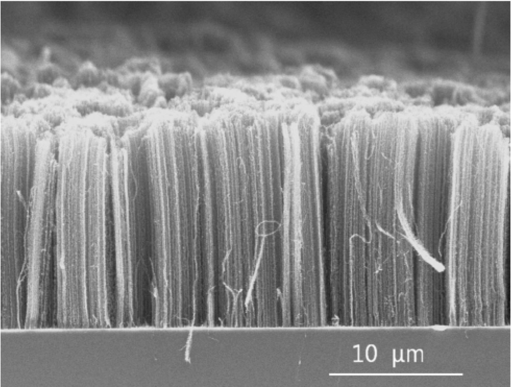
FIGURE 2. Methane pyrolysis processes can produce several forms of carbon, such as carbon nanotubes, like those shown here. Photo Credit: Fromm
FIGURE 2. Methane pyrolysis processes can produce several forms of carbon, such as carbon nanotubes, like those shown here. Photo Credit: Fromm
Reaction products
As stated above, the main products of the MP reaction are H2 and solid carbon. The main uses of H2 include:
- A reactant for production of basic chemicals (such as ammonia), petroleum refining, reduction of metal oxide ores, hydrogenation of fats and other processes
- A clean (no carbon emissions) fuel for processes requiring high-temperature heat, such as ore smelting, calcination, manufacture of cement, glass, ceramic materials and others
- A clean fuel for electric power generation and for propulsion of ships, locomotives and aircraft using either direct combustion or fuel cells. Automotive use is limited by lack of large-scale H2 distribution infrastructure, although this can be changed by distributed modular MP systems
Produced elemental carbon can be used commercially as a filler for tire rubber and plastics, a pigment for ink and coatings, an adsorbent, a reducing reactant for pyrometallurgical applications, for electrodes manufacturing, and more recently, as a filament for production of structural polymers using carbon fibers, nanotubes (Figure 2) or graphene.
If the MD process is deployed on a large scale commensurate with the current H2 world-wide demand (around 97 million metric tons H2/yr), the solid carbon produced (294 million m.t./yr of C) would far exceed current combined demand for carbon black, graphite, metallurgical coke, and anode coke (50 million m.t./yr of C). Unless new high-volume commercial uses are established, this huge excess of 244 million m.t./yr of C would have to be land-disposed (for example, in abandoned mines). This problem would be exacerbated if future demand for H2 is increased — for example, replacing coke with H2 in steel manufacture can increase H2 demand by 90 million m.t./yr alone.
Perpetual storage of solid carbon does not pose the risk of CO2 releases associated with CCS, which involves transporting and storing of liquefied or supercritical CO2 under pressure in geological formations. Instead, the risks include carbon dust explosions and potential toxicity due to presence of residual carcinogenic polycyclic aromatic hydrocarbons (PAH). Fortunately, both of these risks can be mitigated. Unlike CO2 pipelines required for CCS, transportation infrastructure for bulk solids is firmly in place. Also, filling empty mines with carbon could preserve some coal-mining jobs.
History of MP processes
Thermal decomposition of hydrocarbons has been known and practiced for well over a century with the first patent issued in 1891. Most applications have dealt with cracking of hydrocarbons in petroleum refining to produce smaller and more useful molecules. Past commercial applications of MP were limited to production of acetylene and of carbon black using Hüls process based on thermal plasma arc reactor [30].
In the second half of 20th century, MP was commercially employed in 1989 to produce commercial carbon black and hydrogen as a byproduct [31]. This thermal plasma arc process was developed jointly by Kvaerner and SINTEF starting with 150 kW test reactor in Trondheim, Norway, followed by 3-MW pilot plant in Bofors, Sweden that led to commercial size Karbomont plant near Montreal, Canada. The plant started operations in 1998 but closed down in 2002 because of financial difficulties and technical problems.
The Kvaerner/SINTEF technology for non-metallurgical applications was subsequently acquired and improved by Monolith Materials, a U.S. company, who is currently the only commercial producer of carbon black and hydrogen via MP in the world. The undergoing expansion of their Olive Creek operating facility in Hallam, NE will result in the plant capable of producing 180,000 m.t./yr of carbon black and 60,000 mt/yr of H2, most of which will be used to produce 290,000 m.t./yr of anhydrous ammonia onsite.
In recent decades, MP has garnered a lot of attention because of its promise to decarbonize hydrogen production in a cost-effective and energy-efficient way. In addition to thermal plasma reactors, several other routes have been identified and are in different stages of development.

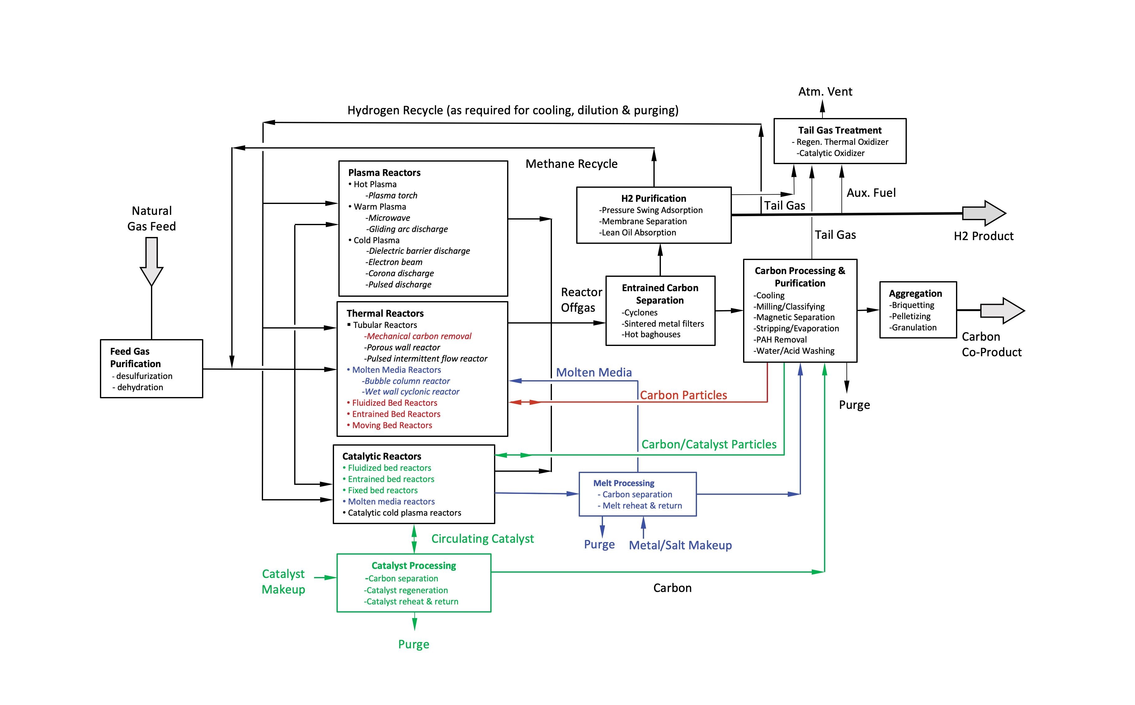
FIGURE 1. This flow diagram shows the elements of a generic methane-pyrolysis process used in manufacturing turquoise hydrogen.
FIGURE 1. This flow diagram shows the elements of a generic methane-pyrolysis process used in manufacturing turquoise hydrogen.
Process configuration
The block flow diagram shown in Figure 1 shows a generic MD process and outlines various technology alternatives. Brief descriptions of the process steps follow.
Feed purification. Pipeline-quality natural gas feed may be treated with zinc oxide (ZnO) to remove odorant mercaptans and any residual H2S prior to reaction to avoid metal catalyst poisoning. For thermal or carbon-catalyzed reactors, the desulfurization step is not necessary, since minor amounts of H2S and mercaptans in the feed actually promote methane decomposition in the presence of carbon [7]. In general, small concentrations of C2 to C6+ hydrocarbons, CO2, N2 and H2O should not significantly affect the methane pyrolysis process, although their process fate, such as methane-water reactions leading to CO or CO2 formation, needs to be considered in the overall process design. One concern arises if C2+ hydrocarbons are present in NG at higher concentrations, which could lead to excessive carbon deposition. Mitigation measures may include pre-pyrolysis reactors [8].
Methane pyrolysis reactors. Methane pyrolysis reactors can be grouped into three categories: plasma, thermal and catalytic. Table 2 contains descriptions of each reactor type.
Entrained carbon separation. Carbon particles entrained in the reactor exit gas can be separated using cyclones, sintered-metal filters or high-temperature baghouses equipped with ceramic filter elements.
H2 purification. In this step, H2 is separated from unreacted CH4, C2+ hydrocarbons and other species present in the filtered and cooled reactor offgas. The separated hydrocarbon-rich stream is recycled back to the reactor. Separation processes include pressure-swing adsorption (PSA), membrane separation and lean oil absorption/desorption. These processes can also be used to remove non-hydrocarbon species (such as N2, CO2, H2S and H2O) from the reactor offgas. To prevent their buildup, the hydrocarbon-rich recycle stream must be purged, or a separate stream containing these compounds would have to be generated (for example, through staged PSA depressurization and purge sequence).
A portion of the purified H2 may be recycled back to the process for plasma-gas generation and/or cooling, heating, dilution or purging needed to minimize carbon deposits on feed-gas injection nozzles or reactor walls.
Tailgas treatment. Since the purge or the tailgas may include small amounts of hydrocarbons, CO, or H2S, direct atmospheric discharge may not be acceptable without treatment using either regenerative or recuperative/catalytic oxidizers. To minimize carbon footprint, high energy efficiency is required, and produced H2 should be considered for auxiliary fuel.
Carbon processing and purification. Separated carbon that exits the reactor, cyclone, or filter as a dense particulate stream may require cooling prior to subsequent steps. This can be performed in bulk solids coolers employing vertical plate or tube coil exchangers, rotary coolers or jacketed augers.
Size reduction using high-velocity gas jets, micro-pulverizers, or continuous ball, rod or pebble mills, along with the particle size classifier and recycle may be necessary to produce particles suitable for recirculation back to a fluid-bed or to a moving-bed reactor after reheating.
Carbon co-product may have to be stripped of adsorbed H2, H2S, CH4 and larger hydrocarbons to alleviate safety concerns in downstream handling. Stripping may be performed using steam-blown or air-blown rotary drums or fluid beds. If reducing residual PAH concentrations is desired, carbon can be heated to high temperatures to volatilize and/or pyrolyze PAH while stripping lighter species. Alternatively, PAH may be removed using solvent extraction [9] and possibly recycled back to the MP reactor. Stripper off-gas should be routed to the tailgas treatment before atmospheric venting.
Carbon particles removed from molten media reactors may be contaminated with salts or metals, which can be removed by evaporation in a rotary kiln or in a tunnel furnace. Water-soluble salts may be removed by a water washing cascade with an evaporator/crystallizer to recover the salts, and a dryer to dry washed carbon product. Metal contamination may also be removed by particle-size classification, magnetic separation or acid washing.
Carbon aggregation. In this step, fine carbon particles are aggregated to mitigate dusting from subsequent solids-handling operations and the associated safety and environmental concerns. Particle size can be increased through briquetting, extrusion granulation or pelletizing after addition of suitable binders. Other steps may be required for carbon nanomaterials.
Melt processing. This step is needed for molten-media reactors to remove any carbon and impurities present in the melt to prevent their accumulation to unacceptable levels. While carbon can be removed by melt filtration, dissolved contaminants may require purging, which necessitates makeup or periodic replacement. Purged molten metal can be solidified and recycled offsite. Purged salt may have to be disposed of as process waste. A melt circulation loop with a reheater and electromagnetic pump can be used as a heat carrier, although heating coils placed inside the reactor can also provide this function.
Catalyst processing. Catalyst mixed with carbon is withdrawn from fluidized- or moving-bed reactors as a dense particle stream. Processing may entail milling followed by separation of carbon and catalyst through sieves or particle-size classifiers. It also can include catalyst regeneration, whereby carbon deposits are burned off or gasified using steam, and catalyst reheating prior to recycling back to the reactor. Catalyst purge and makeup are also performed at this step. Molten-media catalysts require purification, purge and makeup (see melt processing). The recirculating catalyst stream can be reheated before returning to the reactor to serve as reaction heat carrier.

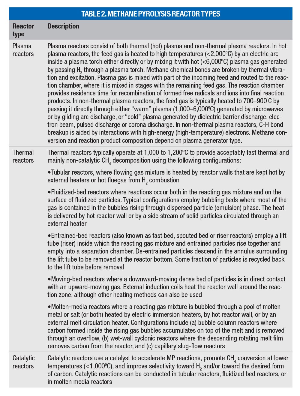

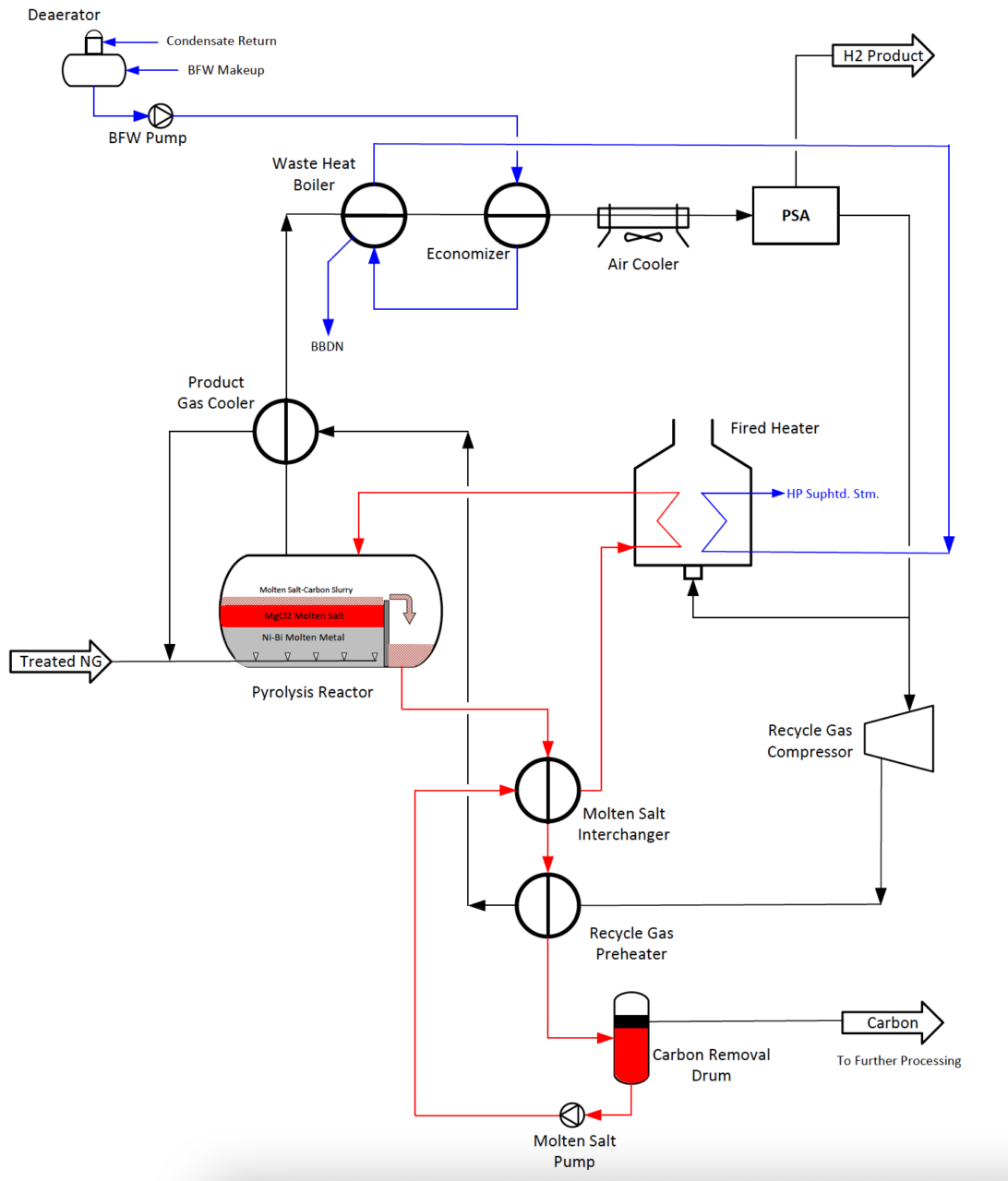
Figure 3. Heating of bubble-column reactor using forced circulation of molten salt (adapted from Parkinson et al. [25])
Figure 3. Heating of bubble-column reactor using forced circulation of molten salt (adapted from Parkinson et al. [25])
Technical challenges
The MP process poses technical challenges. Four of the main ones — carbon deposition, slow reaction, delivering heat to the reactor and heat recovery — are discussed below.
Carbon deposition. Carbon deposition on internal surfaces of tubular reactors leads to reactor plugging and unstable operation. Fouled reactors must be periodically shut down to remove carbon deposits from the walls and feed-gas injectors, and replacing or regenerating the fixed bed of catalyst. This necessitates the use of multiple parallel reactors to maintain production continuity, which adds cost and considerable complexity to the process.
Mitigation approaches include the use of a wet-wall reactor, where the internal reactor surface is wetted by a rotating or falling film of liquid metal or salt [10], a porous-wall reactor (in the context of methane chlorination leading to hydrogen and carbon) [4], or using less adherent surfaces, such as calcium-oxide wall coating to facilitate mechanical carbon-deposit removal [11] or ceramics, including alumina, MgO-C, or SiC [8].
Carbon buildup in plasma torches was addressed by the company HiiROC (Hull, U.K.; www.hiiroc.com) by using H2-purged porous anodes in combination with vortex flow inside the torch chamber [12].
Ekona Power Inc. (Burnaby, B.C.; www.ekonapower.com) developed a pulsed intermittent-flow reactor where carbon deposition is mitigated by strong turbulence associated with rapid depressurization and high-velocity gas flow [13]. Nonrecoverable ferrocene Fe(C5H5)2 and sulfur adjuvants have been used to promote carbon nanotube formation without carbon wall deposits in a downflow tubular reactor tested by Huntsman (The Woodlands, Tex.; www.huntsman.com) for production of Miralon, a carbon nanotube material [14, 15].
Prevention of carbon buildup led to the development of fluidized-bed reactors, moving-bed reactors and bubble-column reactors, all of which are being actively pursued by commercial firms. In the fluidized-bed reactors, carbon preferentially forms on the surface of fluidized particles which grow in size and are continuously removed from the bed by gravity-settling below the gas distributor or using an internal overflow weir near the top of the bubbling fluid bed, as in the process developed by Pacific Northwest National Laboratory (PNNL; Richland, Wash.; www.pnnl.gov) that uses fluidized iron-based catalyst [16].
Alternatively, fluidized catalyst particles can undergo attrition and phase transformation inside the bed, releasing accumulated carbon in the form of fine particles that are entrained into reactor gas and then elutriated out of reactor, as is done in the Hazer Group Ltd. (Perth, Australia; www.hazergroup.com.au) process that uses iron ore catalyst in multistage fluidized-bed reactors [17].
In the moving-bed reactor being developed by BASF SE (Ludwigshafen, Germany; www.basf.de) [18], a dense phase of carbon particles moves downward countercurrent to the gas flow inside a cylinder equipped with the hot wall reaction section heated by external induction-coil. Hot solid carbon particles exchange the heat directly with the reacting gas moving upward. Carbon particles grow due to deposition of formed carbon on their surface which, along with the wall shear forces, prevents carbon deposit on the reactor walls.
Bubble-column reactors mitigate carbon deposition, as the reactions take place inside gas bubbles rising through a pool of molten media, such as metals (Sn, Pb, Ga, Te, Ni-Bi, Cu-Bi, Ga-In-Sn) or salt (KBr, NaBr, NaBr/KBr, NaF, KCl, NaCl, MnCl2), acting as heat transfer fluids at 900–1,400ºC and often as catalysts. Molten media is contained inside a cylindrical reactor that may be provided with a submerged packed bed of ceramic rings or sprays in the vapor space to increase liquid-gas interface. Carbon wall deposits are mitigated by carbon formation at the bubble-liquid interface, which keeps it contained inside the bubble. When rising gas bubbles burst upon reaching liquid surface, carbon is released and floats on the melt surface, from where it can be continuously removed using an overflow weir or gas flushing.
Slow reaction. As discussed above, the methane pyrolysis reaction is relatively slow. While raising the reaction temperature helps, when temperatures exceed 1,300ºC, the equilibrium yield of H2 starts to decrease due to the formation of acetylene, ethylene and ethane. Moreover, higher temperatures result in higher net energy consumption. To lessen the residence time and the reactor volume, it is possible to increase reactor pressure, but at the expense of H2 yield. For these reasons, reactor design must carefully examine H2 yields and exit gas compositions as a function of reaction temperature and pressure along with staged feed-gas injection and staged dilution/cooling with H2. Multiple competing reactor configurations need to be analyzed using kinetic modeling to optimize the reactor design.
Various catalysts have been developed to accelerate MP reactions at lower temperatures (<1,000ºC) and to improve selectivity toward H2 and desired allotropic form of carbon; these include the following:
- Solid catalysts, such as metals (Co, Fe, Ni, Si), metals/alloys with promoters/dopants (Ni-Cu, Ni-Pd, Ni-Mo, Ni-La, Ni-Cu-Co, Ni-Sn, Fe-Co, Fe-Mo, Zn-Cu) supported on silica, alumina or carbonaceous materials, metal oxides (FeO/Fe2O3, La2NiO4), metal carbides (Fe3C, Ni3C), and metal-carbon nanostructures (Ni-C)
- Molten-media catalysts, such as liquid metals (Te, Ni-Bi, Ga, Pb), liquid salts (NaCl, KCl, MnCl2, NiCl2, NaBr, KBr, Na2CO3, K2CO3, Li2CO3, or their mixtures), liquid salts with dispersed solid catalyst particles in the form of finely divided elemental metals (Ni, Mo, Mn, Co, Fe, Zn, Ti, Cu), their oxides, carbides or their mixtures, and carbon catalysts (activated carbon, carbon black, graphite and formed carbon). A recent comprehensive review of MP catalysts was conducted by McConachie [8].
Relative to solid catalysts, molten-media catalysts are not prone to carbon buildup. However, their stability is affected by high temperature. Metal catalysts’ activity depends on the metal (Ni>Co>Fe) and exceeds that of carbon catalysts [7]. Rapid solid catalyst deactivation caused by carbon buildup, poisoning and sintering is the key concern. Susceptibility to deactivation is higher for Ni-based catalysts than for Fe-based and carbon-based catalysts.
Conventional reactivation of solid metallic catalysts removes carbon deposits using oxidation or steam gasification, and results in CO2 emissions. This is avoided in the process developed by PNNL, where bimetallic Ni-Cu catalyst on a carbon nanotube support is used to pyrolyze methane at 600°C inside a fluidized bubbling-bed reactor [16]. Formed carbon accumulates on catalyst particles, which are withdrawn from the bed, cooled and acid-washed to separate formed carbon from metallic catalyst precursors. Catalyst precursors are then used to resynthesize the catalyst for recycle back to the reactor. The catalyst can be formulated to increase selectivity toward formation of carbon nanotubes.
Iron-based solid catalysts are more stable and deactivate at slower rates than Ni-based catalysts. The process developed by Hazer Group uses fluidized iron ore (Fe2O3/FeO) catalyst particles [17]. Carbon forms as graphite on the surface of catalyst particles, which undergo continuous attrition through intergranular breakup, releasing small graphite particles into the reactor offgas. Catalyst surface is thus continuously regenerated, preventing deactivation due to carbon buildup. Separation of elutriated solid catalyst from carbon is one of the challenges in such systems.
As previously mentioned, special once-through non-recoverable “catalysts” have been used to promote carbon nanotube formation in tubular MP reactors. These include ferrocene Fe(C5H5)2 and sulfur additives. Use of ferrocene and iron pentacarbonyl Fe(CO)5 was investigated for the production of hydrogen in solar-heated reactors [28].
Carbon catalysts are considerably less expensive, but also are less active than metallic catalysts, leading to higher operating temperatures (800–1,000ºC) and longer residence times to achieve equivalent conversion. Amorphous carbons (carbon black, activated carbon) are more active than ordered forms, such as graphite. Advantages for carbon catalysts over metallic catalysts include negligible toxicity, high stability, longer lifetimes and no susceptibility to sulfur poisoning, which makes desulfurization of the natural gas feed unnecessary.
Regeneration of carbon catalysts may be performed through gasification with steam, which generates CO2 and H2. However, this is not needed for the once-through use of imported carbon catalyst with higher activity, such as activated carbon. Also, it may be preferable to rely on autocatalytic properties of formed carbon product instead of a once-through use of imported catalytic carbon, as practiced by Modern Hydrogen Inc. (Bothell, Wash.; www.modernhydrogen.com).
Low catalytic activity of formed carbon can be compensated for by increasing the circulation rate of carbon product through the reactor, which increases the exposed particle surface area within the reactor.
Methane decomposition can also be achieved through photolysis using heterogenous photocatalysts inside fixed-bed tubular reactors with transparent walls illuminated by external light.
Delivery of heat to the reactor. In addition to the enthalpy required by the endothermic MP reaction, sensible heat is needed to get the reactants to the desired temperature. The overall reaction heat requirement depends on the size of the recycle streams, and can amount to 1.2–1.5 times the reaction endotherm.
In plasma reactors, the heat requirement is provided by electricity powering a plasma generator. Hydrogen or staged feed-gas injection can be used to control the temperature profile. No additional heat source is required.
In non-plasma small-scale experimental reactors, heat is typically delivered to the reacting mixture through a hot reactor wall, whereby the reactor is placed inside an electric furnace or heated using external resistors or induction coils. Such a scheme does not scale up well with growing reactor diameter, because the radial temperature gradient becomes very steep and efficient heat transfer becomes more difficult.
To circumvent scaleup issues associated with externally heated reactors, pilot- and demonstration-scale plant design should consider a circulating side-stream of molten metal or salt, carbon particles or catalyst particles, as a heat carrier. Circulating stream(s) would be withdrawn from the reactor, processed as necessary, reheated and recycled back. External reheaters can utilize resistive, induction and microwave heating, electric arc furnace, H2-burning fired heaters, concentrated solar heating or immersed plasma torch (molten media only).
One example of MP reactor heating is shown in Figure 3, where molten salt floating on top of a molten Ni-Bi catalyst pool is circulated through an external-fired heater before returning to the bubble-column reactor.
Using combustion heat to provide MP endotherm was explored by Muradov [27], whereby a small amount of oxygen is added to a fluidized-bed catalytic reactor employing carbon and iron-based catalyst. Emissions of CO2 would still be 3–5 times smaller compared to the conventional SMR process. A similar approach is used by C-Zero, whereby H2 is combusted to heat a circulating molten media inside a bubble column reactor.
Other schemes of delivering heat to reactors are being researched. One of them under development by Palo Alto Research Center [19] involves condensation of zinc vapor to supply the reaction heat inside a molten zinc cyclone reactor. A scheme proposed by Munera-Parra [20] uses chemical energy obtained through exothermic recombination of molecular hydrogen from plasma-generated atomic hydrogen. A novel method utilizes compression heating of methane to pyrolysis temperature using a supersonic shock wave generated by wave rotor reformer technology [21]. Microwave heating of fluidized bed was patented by H-Quest [22].
Heat recovery. The overall heat requirement can be significantly reduced by using heat recovery from reactor outlet streams, or by utilizing waste heat from adjacent processes (for example, from cooling of steel and slag in steel production served by dedicated MP installations) [29].
Heat can be recovered by preheating the feed stream (natural gas mixed with methane recycle) and H2 recycle stream against the reactor exit streams. Caution must be exercised to avoid coking inside heat exchanger tubes due to overheating of the feed stream.
Owing to the high heat capacity of H2, most of the heat leaving the MP reactor (~80%) is carried by the gas with the remaining 20% carried by carbon. The entire reactor offgas stream can be sent through a shell-and-tube heat exchanger prior to the solids separation step, as practiced in some carbon black plants. Alternatively, hot carbon is separated in a cyclone or inside the reactor, prior to heat recovery from the solids-free gas through steam superheating, followed by steam generation, and followed by an economizer. Heat can be recovered from carbon using a bulk solids cooler equipped with a vertical plate or coil-tube exchanger.
Superheated steam can be utilized in a combined-cycle cogeneration system employing H2-fueled gas turbine to generate power for the plant, as well as for export. Such a system would also provide operational flexibility to accommodate swings in external H2 demand.
For more information, see the article, Commercial Progress on Turquoise Hydrogen.
MP process economics
Publications dealing with techno-economic analysis of MP technologies use a wide-ranging set of assumptions, methodologies, plant capacities and unit pricing of natural gas, carbon, electricity, water, consumables, labor, carbon-offset credits and other parameters. Because of this variability, the published data do not allow for equitable comparison of projected economic performance of competing technologies. Nevertheless, reviewed articles provide valuable insights into expected economic performance of methane pyrolysis technology and are summarized as follows (for uniformity, all costs are expressed in 3Q 2023 dollars):
- Hydrogen production costs using SMR-CCS technology varied from $1.40/kg to $2.50/kg of H2, depending on natural gas cost and other factors used in analysis [23, 24, 16]
- For molten salt (KCl-MnCl2) bubble-column reactors, projected H2 production cost was $1.80/kg of H2 based on natural gas at $2.30/GJ and zero revenue for produced carbon [24].
- Hydrogen from molten media (Ni-Bi metal and salt) reactors costs $1.70/kg of H2 to produce, which is much less than water electrolysis based on polymer electrode membrane (PEM) technology ($3.00/kg H2 for electricity cost alone). A carbon-offset credit of $26/ton CO2 is required to achieve cost parity with SMR. Alternatively, carbon co-product revenues would have to exceed $200/ton carbon for the same effect [25].
- For fluidized-bed reactors using solid Fe-based catalysts, projected H2 production cost was $3.20–3.50/kg H2 based on natural gas at $7.50/GJ, with zero revenue for produced carbon, and no catalyst recycle or carbon purification, all against $2.50/kg H2 for SMR-CCS benchmark. For H2 to become competitive with SMR-CCS, 20% of produced carbon would have to sell at $1.20–1.50/kg. The economics and thermal efficiency are highly sensitive to catalyst activity and resulting H2 yield [15].
- Carbon co-product revenue in the $600–900/ton range will completely offset H2 production cost [26].
- The H2 production cost from a fluidized-bed MP reactor will match that of an SMR process (without CCS) if carbon sells for $300–800/ton [27].
- Production cost of H2 from the MP process based on a hot cyclone reactor wetted by liquid Zn metal is $2.50/kg of crude (94%) H2, and $3.40/kg pure (99%+) H2 with zero carbon revenues for both cases [19].
Overall, turquoise H2 can be produced at $1.80–4.00/kg without carbon sales or offsets, which is not yet cost-competitive with grey H2 ($0.90–3.00/kg to produce). However, turquoise H2 may compete favorably with blue hydrogen produced at $1.40–2.50/kg by SMR-CCS.
The economic feasibility of turquoise hydrogen can be vastly improved by selling carbon co-product and generating revenue from carbon-offset credits or from avoided carbon tax (for example, obtained by replacing SMR or oil-derived carbon black plants with an MP process).
Economic feasibility can also be improved through technical innovation. For example, the ETCH process [5] that employs Ni-based redox reactions is projected to produce H2 at $1.00–1.50/kg of H2 without carbon sales or carbon offsets revenue, which compares favorably to SMR.
Current growing demand for carbon black and graphite creates significant market opportunities for MP-produced carbon. However, new markets for carbon are needed to strengthen the driving force required for broad adoption of MP technology.
Large-scale grassroots MP plants will have to compete with fully amortized existing H2 plants. For this reason, it may be worthwhile to consider the feasibility of retrofitting the existing installations with MP reactors and solids handling subsystems.
Edited by Scott Jenkins
References
- Koch, T., Blank, P. Moll, Hydrogen’s Decarbonization Impact for Industry, Rocky Mountain Institute, Insight Brief, January 2020.
- Kelsall, G., Hydrogen from Coal, Coal Age, May 7, 2021.
- Gorski, J., T.Jutt, T., Tam Wu, K., Carbon Intensity of Blue Hydrogen Production, Pembina Institute, Technical Paper, August 2021.
- Becker, T., Keuchel, F., Agar, D.W., CFD Modeling of Reactor Concepts to Avoid Carbon Deposition in Pyrolysis Reactions, Chem. Ing. Tech., 93, No. 5, 762–220, 2021.
- Erlebacher, J., Gaskey, B., Method of CO2-free Hydrogen Production from Hydrocarbon Decomposition over Metal Salts, U.S. Patent 9,776,860, Oct. 2017. Also https://etchmaterials.com.
- Becker, T., Richter, M., Agar, D.W., Methane Pyrolysis: Kinetic Studies and Mechanical Removal of Carbon Deposits in Reactors of Different Materials, Intl. J. Hydrogen Energy, 48 2112–2129, 2023.
- Sanchez-Bastardo, N., Schlögl, Ruland, R.H., Methane Pyrolysis for Zero Emission H2 Production: A Potential Bridge Technology from Fossil Fuels to a Renewable and Sustainable Hydrogen Economy, Ind. Eng. Chem. Res., 60,11855–11881, 2021.
- McConnachie, M., Konarova, M., Smart, S., Literature Review of the Catalytic Pyrolysis of Methan for Hydrogen and Carbon Production, Intl. J. Hydr. Energy 48, 2560–2582, 2023.
- Lau, E.V. et al., Extraction Techniques for Polycyclic Aromatic Hydrocarbons in Soils, Intl. J. Anal. Chem., 381–398, 2010.
- 10. Becker, T., Agar, D.W., Theoretical Studies of a Rotating Film Reactor for H2 Production from Methane, Chem. Ing. Tech., 94, (5), 681–689, 2022.
- Jensen, R., van der Eijk, C., Waernes, A.N., Production of Sustainable Hydrogen and Carbon for the Metallurgical Industry, Mater. Proc., 5, 67, 2021.
- Anon., HiiROC $34M for thermal plasma electrolysis of natural gas, Technology Wealth, Dec 8, 2022.
- Ekona Power ($68M for pulsed natural gas pyrolysis), Technology Wealth, Dec. 3, 2022.
- Gaius, D., Structural, High-Value Carbon and Hydrogen from Natural Gas, Huntsman Merrimack/Advanced Materials slide presentation at U.S. Dept. of Energy ARPA-E Carbon Cohort Conference, Las Vegas, Nev., Jan. 2021
- Huntsman website: www.huntsman.com/products/.
- 16. Riley, C. Atallah, R. Siriwardane, R. Stevens, Technoeconomic Analysis for Hydrogen and Carbon Coproduction via Catalytic Pyrolysis of Methane, Intl J Hydrogen Energy, 46, 39 (2021), 20338-20358.
- Hazer Group website: hazergroup.com.au.
- Bode, A and Flick, D., A Potential New Process for H2 Production without CO2 Emissions, slide presentation at ARPA-E Methane Pyrolysis Program Review Meeting, Jan. 12 and 14, 2021.
- Rupp, B., High Throughput Methane Pyrolysis for Low Cost, Emissions-Free Hydrogen, ARPA-E Methane Pyrolysis Annual Program Review, 2021
- Munera-Parra, A., Reactor Design, Modeling and Optimization for the High-Temperature Methane Pyrolysis and the Reverse Water-Gas Shift Reaction, Doctoral Thesis, Dortmund Technische Universitat, Germany 2018.
- Akbari, P., Copeland, C. D., Tüchler, S., Davidson, M., and Mahmoodi-Jezeh, S. V., Shock Wave Heating: A Novel Method for Low-Cost Hydrogen Production, International Mechanical Engineering Conference, ASME Paper,-69775, Online, 2021.
- G. Skoptsov, et.al., Microwave-Assisted Fluidized Bed Reactor, US Patent 20220362731A1.
- Katebah, M., Al-Rawashdeh, M., Linke, P., Analysis of Hydrogen Production Costs in Steam-Methane Reforming Considering Integration with Electrolysis and CO2 Capture, Cleaner Eng. & Tech., 10, 100552, 2022.
- 24. Pruvost, F. et al., Techno-Economic Assessment of Natural Gas Pyrolysis in Molten Salts, Cleaner Eng. & Tech., 10, 100552, 2022.
- Parkinson, B., Tabatabaei, M., Upham, D.,Ballinger B., Greig, C., Smart, S., McFarland, E., Hydrogen Production Using Methane: Techno-economics of Decarbonizing Fuels and Chemicals, Int J Hydrogen Energy, 43 (5), pp. 2540–2455, 2018.
- Timmerberg, S. et al., Hydrogen and Hydrogen-Derived Fuels Through Methane Decomposition of Natural Gas – GHG Emissions and Costs, Energy Conversion and Management X, 7, 100043, 2020.
- N. Muradov, Thermocatalytic CO2-free Production of Hydrogen from Hydrocarbon Fuels, Proc. DOE Hydrogen Program Review, NREL/CP-57-30535, 2001.
- J. Yeheskel, M. Epstein, Thermolysis of Methane in a Solar Reactor for Mass Production of Hydrogen and Carbon Nano-Materials, Carbon, 2011,49 (14), 4695-4703
- A.L. Gusev, et.al., Production of hydrogen and carbon in the petrochemical industry by cracking of hydrocarbons in the process of heat utilization in steel production, Intl J Hydrogen Energy, 48, 40, (2023), 14954-14963,


Author
Carl Fromm is a process engineer and project manager with consulting firm Green Star BCS LLC (840 Gessner Rd., Suite 250, Houston, TX 77024; Email: carl_fromm@yahoo.com). He has close to 50 years of experience in process development and plant design covering a wide range of industries, including petroleum refining, chemicals, pharmaceuticals, metallurgical, utilities and environmental protection.