Adding an organic Rankine cycle system to generate power onsite can help operators optimize the overall economics of combustion-related systems and emissions controls
The ever-increasing cost of fuel and relentless push for environmental responsibility are constant factors in the profitability of many chemical process operations, and fluctuations in the prices of natural gas and other fuels can make it hard to predict future energy costs and the impact of such fluctuations on profits. However, the impact of fluctuating fuel costs, and the regulatory uncertainty related to managing emissions can be reduced by increasing energy efficiency and incorporating innovation into the design of any combustion-related system that produces fluegas.
Numerous industrial processes involving furnaces, heaters, kilns and boilers that combust fossil fuels release large quantities of energy in the form of waste heat that is contained in the fluegas. An organic Rankine cycle (ORC) system can efficiently utilize this waste heat to generate electricity, even from relatively low-temperature fluegas streams.
An ORC resembles a typical Rankine cycle, but instead of circulating water as the working fluid, an ORC uses a refrigerant — typically an organic fluid such as ethane, propane, propylene or various name-brand refrigerants, such as R-245fa (discussed below). An ORC also operates at lower temperatures compared to the more widely used steam-based Rankine systems. For instance, steam-based systems typically operate at temperatures corresponding to low-pressure steam; that is 250°F or higher. By comparison, an ORC can efficiently operate at temperatures below the boiling point of water, from 212°F to as low a temperature as desired for a given application. Thus, the use of an ORC can be a more cost-effective method for capturing waste heat from fluegas compared to the use of a traditional steam-based Rankine cycle. This is accomplished by reducing fluegas temperatures below what is possible in a steam-based system without the need for a complex heat exchange system.
When properly designed, an ORC system can remove more heat from a fluegas stream than a steam-based Rankine system and thus can be effectively used with cooler fluegas streams compared to those produced by steam-based Rankine systems.
Meawhile, most fluegas-treatment methods, such as those involving fluegas scrubbing, carbon capture, and carbon sequestration require the fluegas stream to be cooled prior to its introduction into the treatment train. Thus, the addition of an ORC system can be of great benefit when used in combination with a downstream flue-gas-treatment system, and can help to improve the overall economics of fluegas treatment by generating additional power from waste heat in the fluegas stream — heat that would otherwise simply be lost to cooling water or to the atmosphere.
The basic ORC scheme
The simple process flow diagram that is provided in Figure 1 shows a basic ORC system. The liquid refrigerant (also called the working fluid) flows from the surge drum ( D-100) to the pump ( P-100) where the fluid is pressurized. The pressurized fluid is then sent to the evaporator ( E-100). The evaporator vaporizes the working fluid by heat exchange with the fluegas stream. Once vaporized, the working fluid then enters the turbo-expander/generator ( T-100) where, by process of expansion, the fluid produces usable work in the form of electrical energy. After expansion, the fluid enters the air-cooled condenser ( E-101) where it is condensed back to liquid form and returned to the surge drum.
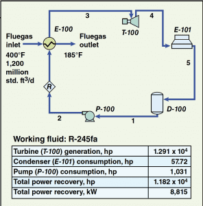
Figure 1. This simulation flowsheet for an ORC system shows the basic equipment, flow streams and power requirement and recovery based on R-245fa as the working fluid. The stream numbers indicate the order in which the streams flow
Figure 1 also provides values for the basic fluegas stream variables along with a small table that shows the quantity of power produced by the turbo-expander/generator train, the components that are power consumers (and their respective power consumption), and the net power recovered by the system.
Power-recovery rates will vary for different applications based on fuel and fluegas composition. The case illustrated in Figure 1 is based on a typical fluegas flowrate, temperature, pressure and composition [ 1 ] with an ambient air-temperature of 70ºF, and assumes that natural gas is the fuel used by the fluegas source.
The curve shown in Figure 2 can be used to approximate the power-recovery rate for various fluegas inlet temperatures at the assumed ambient temperature. Note that power recovery varies linearly with fluegas temperature for a given ambient temperature and fluegas stream, allowing for easy interpolation to estimate the power-recovery rate for a specific application.
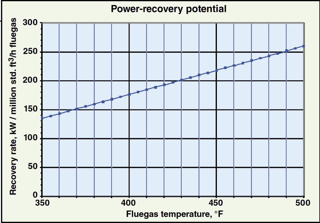 Figure 2. This chart, showing the power-recovery potential |
Equation (1) is derived empirically from simulation data, and can be used to estimate the potential power recovery that is possible when using a simple ORC:
( 1)
P = Net recovered power, kW
Qfg = Fluegas flow, million std. ft3/h
Tfg= Fluegas inlet temperature, ºF
Ta = Ambient temperature, ºF
A = –0.00411 (unitless constant)
B = 0.775 (unitless constant)
C = 1.122 (unitless constant)
D = –211.63 (constant)
This equation produces estimates of fluegas temperatures that have an accuracy of ± 0.23% between 350 and 500ºF with ambient temperatures varying between 50 and 100ºF. Figure 3 illustrates the percent difference in the values calculated by the equation versus those produced by simulation.
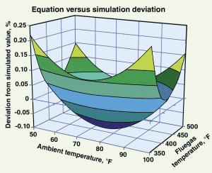
Figure 3. This chart compares the accuracy of the net power recovery estimated using Equation (1) versus the net power recovery as predicted by the simulation model.
As shown, the results predicted by the simulation and the results predicted by the equation differ by no more than -0.1% to +0.23%
Equation (1) also assumes that the cycle is running in the working fluid’s subcritical region. The subcritical region is the ranges of temperature and pressure below the fluid’s critical point — that is, where distinct liquid and vapor phases exist. Note that this equation is only provided for quick estimation purposes. More accurate results can be easily achieved by simulating the simple process.
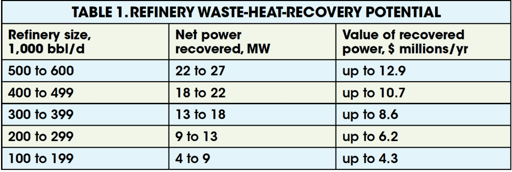
Using Equation (1) to obtain empirical data on fluegas rates and temperatures for various refinery units, it is easy to formulate a table such as that shown in Table 1. Based on the size of the refinery, the potential power recovery and the associated dollar value of the power recovered can be approximated with suitable accuracy. See Figure 4 potential heat-recovery rate. For the case discussed here, the reported dollar values of the power recovered annually are based on a plant on-stream factor of 8,000 hours per year, and a conservative, per kW-h value of $0.06.
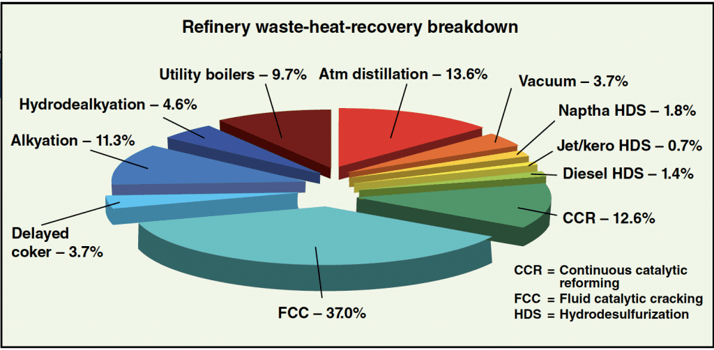
Figure 4. In this breakdown of heat recovery by refinery unit, one can see that particularly high rates of potential waste-heat recovery are possible for fluid catalytic cracking, atmospheric distillation and catalytic reforming units, as well as utility boilers
Various ORC configurations
Although, the main focus of this article is on the use of a simple ORC configuration, specific modifications may be made to the cycle and to improve the heat-recovery efficiency and increase the quantity of power recovered. For example, as shown in Figure 5, if an additional heat exchanger ( E-102) were provided to preheat the refrigerant stream entering the evaporator ( E-100) by heat exchange with the turbine exhaust stream, then an increase in power recovery of at least 10% over the simple cycle may be realized. Depending on the size of the specific installation, this could prove to be a very significant increase.
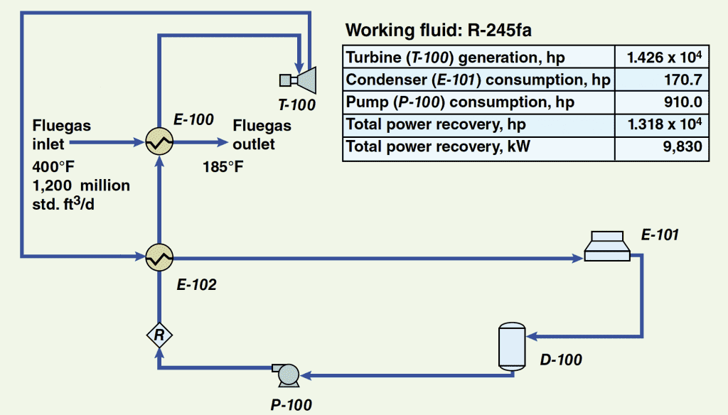
FIGURE 5. The addition of a pre-heater unit (E-102) to this ORC configuration helps the system enhance the overall heat-recovery efficiency and increase the quantity of recovered power
However, while improved heat-recovery efficiencies and the potential to increase the quantity of power recovered are always gratifying, the addition of extra equipment requires additional capital, operations and maintenance expenditures. These additional costs must be weighed against the value of the power recovered. Thus, depending on the required payback time and forecasted energy prices, the addition of a simple ORC system may prove to be the most cost-effective solution for a particular application.
Choice of a working fluid. The simulated properties of the working fluid used in this study are based on the physical properties of the refrigerant R-245fa (1,1,1,3,3 – pentafluoropropane), which has the trade name Genetron and is a product of Honeywell [ 2,3,4 ]. The characteristics of R-245fa make it particularly suitable for fluegas heat-recovery applications using ORC technology. This refrigerant has the required thermodynamic properties — namely, relatively high critical and condensing temperatures — which are necessary for operating in the temperature range between typical fluegas temperatures and the ambient temperature of the heat sink.
This particular refrigerant also has a relatively high decomposition temperature, which is desirable for heat exchange with hot fluegas streams. Furthermore, R-245fa has desirable environmental traits that make it a refrigerant of choice for many industrial refrigeration systems, in light of environmental concerns related to the ozone layer and fugitive emissions. For instance, the fluid has a zero ozone-depletion potential (ODP), a relatively low global-warming potential (GWP), and it is not considered a volatile organic compound (VOC) in the U.S. [ 4 ]
The economics and heat-recovery potential of an ORC are a function of the thermodynamic properties of the selected refrigerant. Thus, the selection of the best working fluid for a given application is important to the successful implementation of any waste-heat-recovery system. Refrigerant blends may also be considered, and the choice of refrigerant or refrigerant blend must be optimized on a case-by-case basis. Designers and marketers of ORC systems and their component machinery have process simulations and empirical data that are needed to accurately model and optimize ORC systems specific to any given fluegas stream.
It is tempting to choose a working fluid based solely on the desire to maximize the power-recovery efficiency, but there are other factors to consider, as well. For instance, depending on the specific application and location of the installation, it may be necessary to select a working fluid that is environmentally friendly, safe, and economical in addition to being inexpensive and readily available.
Air-cooled heat exchangers vs. cooling water. The results of this study are based on the assumption that in the particular application, air-cooled heat exchange is more economical than systems based on cooling water. Air coolers, depending on the cooling duty required, are generally not high energy consumers but they may require a significant amount of plot space. The decision of which type of heat exchange methodology, in terms of capital cost, operating cost, operating logistics and potential impact on the overall heat-recovery potential, must be evaluated on a case-by-case basis for each application.
Acid-gas condensation issues. When establishing the temperature at which the fluegas will exit the waste-heat-recovery unit, consideration must be given to the potential for acid condensation. This occurs when the water vapor in a fluegas stream is allowed to condense, carrying with it any compounds that may form an acid when combined with water.
In most cases, industrial fluegas streams are produced by the combustion of a fossil fuel. In many cases, this fuel contains some form of sulfur, which will likely be converted to some form of SOx during combustion. If cooled below the acid dewpoint, these combustion byproducts, along with carbon dioxide, can combine with the water vapor present in the fluegas stream and form corrosive acids [ 5 ].
To prevent equipment corrosion, any item that comes in contact with the cooled fluegas stream must be constructed of special materials that can withstand damage from such acids, and these special materials can add considerably to equipment costs. Such fluegas systems are also commonly designed to remain above the acid dewpoint to avoid corrosion.
While these design and operating considerations can add considerably to the overall system cost, the condensation of fluegas provides additional opportunity for energy capture, because as the water vapor in the fluegas stream condenses, the latent heat of vaporization of the water will be transferred to the working fluid, thereby increasing the potential power recovered via the ORC system.
An economic analysis must be performed to balance the tradeoffs and determine whether cooling the fluegas stream below its acid dewpoint and capturing the extra energy is worth the additional capital necessary to implement the metallurgical requirements to withstand the potential for acid attack.
Plant economics and air permit benefits of ORC technology. If properly designed, the use of an ORC system can provide a facility with an opportunity to produce additional electric power without an increase in air emissions. As a general rule of thumb, any combustion-related facility can benefit from ORC installations on furnace stacks if electrical power from external sources is limited, expensive, or unreliable by providing the plant with internal power-generation capabilities and an additional source of electricity for captive use at the site.
It is also worth noting that facilities in certain regions face restrictions on air emissions that make it costly or impossible to amend air permits to add furnaces, cogeneration units or other means of increasing utility power, a situation that can limit expansion and modernization opportunities. However, the installation of an ORC system on existing furnaces allows for the generation of electrical power without increasing air emissions by capturing waste heat from furnaces already in operation.
A typical ORC installation will usually generate a significant surplus of electricity compared to the power that its own equipment uses, so an ORC system’s net utility costs are generally less than zero. An ORC system is therefore a minimal contributor to a plant’s overall operating costs, which is another advantage of using ORC technology to improve both fluegas treatment and onsite power generation.
Final thoughts
Ongoing political developments are expected to bring about stricter enforcement of environmental regulations and increased incentives to reduce fossil-fuel consumption and imports, while the escalation of energy prices is tightening profit margins for all chemical process and refinery operators. ORC systems offer a promising means of enhancing waste-heat recovery from fluegas in both existing and new facilities, and thus help to improve the overall economics of fluegas treatment.
Today, thanks to advances in refrigerants (and blends), and ongoing innovations in heat exchange technology, metallurgy, and simulation tools, the classic ORC system can be optimized to fit ideally within a wide range of fluegas sources and treatment systems.
Edited by Suzanne Shelley
References
1. Mahasenan, N., and Brown, D.R., Beyond the big picture: Characterization of CO2-laden streams and implications for capture technologies, “Proceedings of the Seventh International Conference on Greenhouse Gas Control Technologies (GHGT-7),” Vancouver, Canada, September 5–9, 2004, 2005.
2. Thermophysical properties of fluid systems, National Institute of Standards and Technology (NIST) website; Accessed: November 21, 2008; http://webbook.nist.gov/chemistry/fluid/.
3. Pan, Jiang, Wu, Jiangtao, and Lui, Zhigang, Vapor pressure of dimethoxymethane and 1,1,1,3,3-pentafluoropropane, J. Chem. Eng. Data, 51–1, p. 188, 2006.
4. Genetron 245fa Applications Development Guide, Honeywell, 2000 (Genetron is a registered trademark of Honeywell.)
5. Wulfinghoff, D.R., Acid dewpoint limitations on heat recovery, “Energy Efficiency Manual,” Energy Institute Press, Wheaton, Md.,pp. 122–123, 1999.
Authors
 Ali Bourji is a senior technical director at WorleyParsons in Houston ( 6330 West Loop South, Bellaire, TX 77401; Phone: 713-407-5000; Fax: 713-350-1394; [email protected]). He holds a B.S.Ch.E and M.S.Ch.E from the University of Houston and a Ph.D. in chemical engineering from Lamar University. Bourji is a professional engineer and a member of AIChE and NPRA.
 John Barnhart is a WorleyParsons vice-president ([email protected]). A graduate of the University of Houston and a professional engineer, his background includes plant operations, and project and company management. Barnhart is a member of AIChE.
 Jimmy Winningham is a process engineer at WorleyParsons in Houston ([email protected]). He holds a B.S.Ch.E. from Texas A&M University.
 Alan Winstead is a supervising process engineer at WorleyParsons in Houston ([email protected]). He holds a B.S.Ch.E. from Rice University.