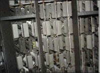
Distillation columns are often workhorses in the chemical process industries (CPI), and at times, it is necessary to physically inspect the interior of a column. This article demonstrates what an inspection can reveal, by sharing the experience of actual fractionation-tower inspections in a petroleum refinery. The points mentioned are intended to provide guidance to future tower inspectors, so that they can focus on extremely important and relevant points that will directly impact the operation of distillation columns.
Inspection basics
Who inspects? Whenever a fractionation tower is opened for inspection, it is important that it be inspected and analyzed by a qualified process engineer, who has been trained in what to look for.
Typically, inspections are carried out by a number of different departments, each one focused on its particular area of concern. Column components are usually inspected by the equipment inspection department. The production department, besides checking if it is necessary to replace or repair internals, inspects if the tower is clean or if it has accumulated large quantities of coke, salt or corrosion products during operation. Cleaning, repairs and mountings are the responsibility of the maintenance department.
The process department inspector is usually responsible for critically analyzing changes made in a column and for identifying potential operational problems. Something as simple as the replacement of a downcomer can generate a significant fractionation-efficiency loss if it is not properly mounted. For example, if the clearance under a downcomer is too small, the column could suffer from flooding because of the flow restriction. The construction crew, however, does not always understand how a column works, and might therefore make decisions that are not the best. It is essential to have people who are knowledgeable about the distillation process to critically analyze and address these types of details in the column. In addition to the critical analysis, it is imperative that the process inspector avoid repeating old practices and errors that can be dragged on for years and become part of the way of working.
Preparing for inspection. A critical inspection is a tedious and often dirty task. It is necessary to remain inside the tower for hours. A job well-done, however, can identify potential problems and will save headaches when the tower is back in operation.
It is important to identify problems before opening the fractionation tower for inspection. Monitoring the variables in the column will allow the inspector to focus on sectors that have been identified as problematic in advance. For example, if the column is flooded at the top, between the kerosene sump and the top of the tower (identified by the differential pressure and gamma scanning), that section should be inspected immediately when the column is opened. In our particular case, we intended to replace the distributors and the wash bed of the vacuum tower, because we knew from monitoring pressure drop during operation that it was filled with a large quantity of coke.
This article covers these examples, and more from the point of view of the process. To put this type of inspection into practice, it is necessary to prepare a detailed program to know what to inspect and how to look for the potential problems. An experienced process engineer once said that a good observer and detector of potential problems inside the column turns himself into the liquid that flows through the downcomers and into vapor, which rises through the trays.
The manufacturing site
This article shares experiences from inspections performed in the vacuum and atmospheric-pressure fractionation towers in our refinery, during routine maintenance shutdowns of the units in November 2008. The refinery, owned by YPF S.A. is called Luján de Cuyo, and is located in the province of Mendoza in Argentina.
Our vacuum tower, CV10, is 37 m long with a diameter of 8.2 m in its largest section. It processes around 9,000 m3/d of atmospheric residue. Our crude distillation atmospheric tower, CV1, is 39.6 m long and 4 m in diameter. It processes around 11,000 m3/d of crude oil.
Full inspections for each of the towers had been planned. Previous planning was necessary to avoid delays and time extensions of the scheduled shutdown. Although a complete inspection of each one of the towers was conducted, this article presents only the points of major interest, which will be useful for process inspectors. We focus on the following points of concern:
Vacuum tower
• Inspection and testing of distributors
• Inspection and testing of sumps and chimney trays
• Inspection of dual-element filter screens
• Design problems
Atmospheric distillation tower
• Inspection of trays (valves, holes, measurements of weirs and clearances under the downcomers)
• Inspection and testing of sumps
• Design problems
• Test of gravity-flow distributor
Vacuum distillation tower
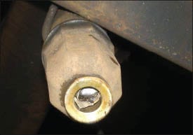
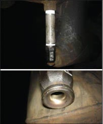
Light vacuum gas oil (LVGO) pump around distributor. Among a total of 19 spray nozzles, only one was found to be plugged. It was agreed with the maintenance staff to randomly select 20% of all nozzles, dismount and check them. If 50% of these nozzles were plugged or dirty, all nozzles would be dismounted for cleaning and inspection.
 |
|
FIGURE 1. Check nozzles for plugs. This one is blocked
with a piece of packing |
 |
|
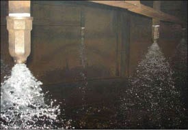
FIGURE 2. Water testing quickly identifies nozzle plugging
|
The nozzle that was found to be plugged (Figure 1), was blocked with a piece of packing (Flexiring). To shed light on our question of how it could have gotten there, we went to inspect the dual-element filter screens that are external to the tower. We found two different possible explanations: 1) We found no meshes inside the filters, and this would allow the packing piece to bypass the filters, and 2) One of the dual-element filters was dismounted to connect a segment of piping that bypassed the dual filters. Someone had decided to dismount it to give operational flexibility to the unit.
Distributor testing. To verify that no spray nozzles had been plugged, they were tested with water. Figure 2 shows what happens when the flow through the nozzles is not adequate. This is due mainly to operational failures, or in the worst case, plugging of the nozzles. A plugged nozzle produces a poor flow for washing on a portion of the bed.
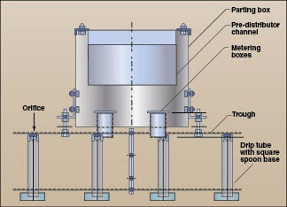
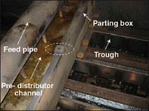
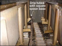
LVGO/heavy vacuum gas oil (HVGO) fractionation bed distributor. We have a gravitational distributor in the LVGO/HVGO fractionation bed (Figure 3). The LVGO fills the pre-distributor channel through a feed pipe. The liquid overflows into a parting box. Then, troughs are filled. At the top of each trough there are orifices, where the liquid flows to drip tubes. The liquid arrives to spoons bases (the liquid drains through the corners of a base, called the spoon base — see Figure 3) and distributes liquid to the bed.
 |
|
FIGURE 3. This schematic shows the configuration
of the gravitational distributor |
The first thing that was observed during the inspection of this distributor was that the central parting box was uneven. Figure 4 shows a missing bolt necessary to hold the box.
Unevenness in the central parting box will affect liquid distribution to the bed below, since the liquid will flow preferentially to some troughs. A section of the packing will be dry due to reduced irrigation, and a poor end point (the highest temperature recorded during distillation) or cloud point (the temperature at which the liquid has a cloudy appearance signifying that wax is beginning to crystallize) would result.
In certain sections, drip tubes with square spoons bases were not in place, but were instead on the bed. Also, as shown in Figure 5, some were bent so that the liquid distribution to the bed was not good.
 |
| FIGURE 4. Inspection uncovered a missing bolt |
 |
|
FIGURE 5. Some drip tubes were bent, causing uneven liquid distribution
|
Even though to enter the column it was (and should be) washed for hours, there was dirt inside the side troughs of the distributor (Figure 6). As the holes from where the liquid enters are above where the dirt was in the troughs, there should have been no obstruction to the passage of liquid. This shows the effectiveness of this design in terms of antifouling.
 |
|
FIGURE 6. Even though dirt was found in the
distributor, the design compensated for the fouling |
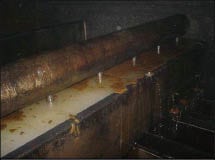
Even with the advantages of this technology, however, the inspection uncovered a clear blockage in the center parting box (Figure 7), which hindered the passage of liquid to the lateral troughs. This was discovered through a water test of the distributor. As a result, the distributor was dismounted and cleaned.
 |
|
FIGURE 7. This blockage required that the
distributor be dismounted and cleaned |
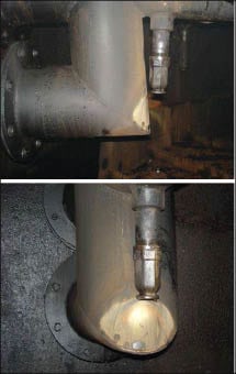
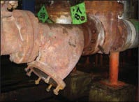
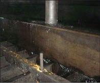
HVGO pump around. We found a design mistake in this section. Figures 8a and 8b show how a branch pipe was wetted by liquid issuing from the spray nozzle. This occurred because the pipe was inclined. Given that the values of total acid number (TAN) and sulfur content of the current HVGO are 1.3 kg (mg KOH per gram of hydrocarbon) and 0.67 wt.% respectively, and the operating temperature exceeds 200°C, the jet flow from the nozzle could negatively impact and contribute to corrosion of the feed piping.
 |
|
FIGURE 8a (top) and 8b (bottom). This design
mistake caused a pipe to be wetted from a nozzle, which could potentially cause corrosion |
To resolve this issue, we tried placing a longer nozzle to stop the liquid from wetting the branch pipe. The tube placed was as long as we could make it, taking the inclination of the pipe into account. Figures 9a and 9b show how the spray distribution would have wetted the branch-pipe weld if we decided to carry out the modification. Once we saw this, however, we became concerned about corroding the weld. Any leak in branch pipe would cause poor distribution over the entire bed, leading to poor heat transfer and possibly coking on the packing. Therefore, we decided to go back to the original arrangement, and we mounted the shorter pipe back, with the compromise to replace it during the next shutdown of the unit.
 |
|
FIGURE 9a and b. A longer nozzle might have
caused a worse corrosion problem to the pipe weld |
While no nozzles were plugged, it is appropriate to comment on another design error as to the dual filters of the HVGO pump-around loop. They are located upstream of the control valve. Dual filter screens should be downstream of any equipment before entering the column, to avoid plugging in the nozzles. This anomaly dates from the construction of the plant in 1970. We will fix them during the next shutdown of the unit.
Wash bed distributor. Before entering the tower for inspection, we observed from the manway that an arm of the distributor was broken, so liquid came out between the two sections. The visual inspection, inside the column, showed that eight out of 61 nozzles were plugged. In this particular case, all the spray nozzles were replaced by new ones, so all of them were dismounted. When we inspected the dismounted nozzles, we were surprised to find that more than eight nozzles were actually plugged. About 50% of the nozzles were plugged internally. This would have probably appeared during the water test of the spray nozzles. The lesson in this case is the importance of the spray-distributor water test.
Each flowstream that circulates to the column contains two “Y” filters (Figure 10). These dual filters are meant to stop any solids that could plug the column internals. We found only one filter whose mesh was deformed (Figure 11), which allowed the passage of dirt to the spray nozzles.
 |
|
FIGURE 10. The “Y” filters were inspected
|
 |
|
FIGURE 11. This deformed mesh taken from
the Y filter would allow solids to pass to the spray nozzles and potentially cause plugging |
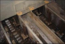
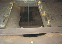
In inspecting the upper grid of the bed, which was raised to the height of the manway, we found a broken tie rod. Figure 12 shows how the grids were deformed. One bed was entirely replaced as planned. One thing to consider is that when the maintenance staff mounted this new bed, they were doing so without drawings. According to design drawings, each bed layer should be at a 45-deg. angle to the layer below, and this was not being respected in the installation. So, we had to intervene to properly reinstall the layers. The lesson here is to try to keep abreast of all changes made. Figure 13 shows a correct flow grid layer arrangement.
 |
|
FIGURE 12. Inspection uncovered deformed
column internals, such as this grid |
 |
|
FIGURE 13. Modifications need to be made
according to design. A correct grid arrangement is shown here |
Atmospheric distillation tower
This column is composed of 39 valve trays and structured packing. From top to bottom, the configuration is the following:
• Trays 1 to 13
• Tray 14 (kerosene sump)
• Trays 15 to 23
• Tray 24 (atmospheric light-gas-oil sump)
• Trays 25 to 33
• Tray 34 (atmospheric heavy-gas-oil sump)
Bottom trays 35 to 39 (stripping section between petroleum feed and stripping steam inlet)
Trays 1 to 10, are two-pass, and 11 to 39 are four-pass trays. The inspection was conducted in detail for each of the trays and structured packing. This article includes only the highlights.
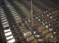
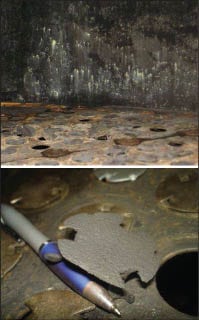
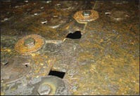
Trays inspection. We found missing valves in some cases along the column, and some valves were found to be corroded (Figures 14a and 14b).
Improper assembly of the panels that compose the trays, produced holes (Figure 15) that allowed weeping, which worsened the quality of fractionation. Besides the formation of holes, improperly placing a panel may negate the functionality for which it was built. Figure 16 shows a panel rotated about its normal position. As can be seen, if the panel is rotated, the inlet weir will not work. The inlet weir function is to prevent the liquid from the downcomer from lifting the valves closest to the inlet downcomer and weeping through the inlet row of valves.
 |
|
FIGURE 14a (top) and b (bottom). Some valves on
|
 |
|
FIGURE 15. Improper assembly of column
internals can lower fractionation efficiency |
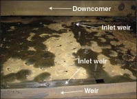 |
|
FIGURE 16. This panel was rotated about its normal
position, rendering the inlet weirs inoperable |
In each of the trays we took measurements of the weirs, and the clearances under the downcomers to ascertain a liquid seal on the tray. If there is no liquid seal, gas may rise up the downcomers, producing liquid entrainment and flooding. Conversely, if the clearance under the downcomer is too small, it will increase the height of liquid in the downcomer. When the downcomer backup reaches the tray above, flooding will occur. It is sufficient to have one undersized clearance to bottleneck an entire fractionator.
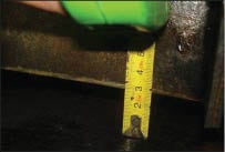
In the particular case shown in Figure 17, the clearance under the downcomer was 29 mm. According to the design drawing, however, this clearance should be 43.5 ± 3 mm. This problem was solved by cutting the bottom of the downcomer to acceptable values.
Between trays 19 and 20 are the atmospheric light-gas-oil (ALGO) pumparound inlet pipe distributors. It was noted during the inspection that during the installation of the distributors in the column, downcomers were damaged (Figure 18). This caused significant losses of fractionation capacity.
 |
|
FIGURE 17. Check that downcomer clearances
are within specifications |
 |
|
FIGURE 18. During installation of the distributors
in the column, downcomers were damaged |
Sumps. Kerosene, ALGO and atmospheric heavy-gas-oil (AHGO) sumps were tested with water. They were filled with water to a certain level. Then we cut off the water and waited about 20 minutes to look at the fall of the water level. The conclusion of the test was that no problems were observed with sump leakage.
Anecdotally, during the final visual inspection of the tower, just before being closed, we found a pipe scaffold in the AHGO sump. It was hiding, so that if we had not properly performed the final inspection, the scaffold debris may have generated significant damage in the area.
Gravity flow distributor. The gravity flow distributor, located in the wash section, was tested with water to see what happens when the flow increases. Figure 19 shows how it fills the central parting box, and the poor distribution of liquid that results when the flow is increased above design values.
 |
|
FIGURE 19. When flow is increased above design
values, poor distribution of liquid results in the gravity flow distributor |
Edited by Dorothy Lozowski
Authors

Juan Manuel Sanchez is the plant engineer of topping and vacuum units at YPF S.A.’s Luján de Cuyo Refinery (Complejo Industrial Luján de Cuyo, Brandsen, PC: 5507, Mendoza, Argentina; Email: [email protected]). He has worked at YPF for seven years. During his six years of process engineering of topping, vacuum and delayed coker units, he has inspected many towers from the point of view of the process. Henry Kister invited him to share his experiences during the 2010 AIChe Spring Meeting, where this topic was presented.

Álvaro Valverde is the process engineer of topping and delayed coke units at YPF’s Luján de Cuyo Refinery (Email: [email protected]). He has three years of experience following and monitoring the variables of these units. Valverde participated in the implementation of the naphtha unit and a new topping furnace. He is also responsible for naphthenic corrosion monitoring.

Carlos M. Di Marco is the plant engineer of coker and diesel hydrotreater (HDS)units at the Luján de Cuyo Refiney (Email: cmdimarcob @ypf.com). Previously, he worked for four years as a process engineer and participated in many turnarounds (amine, crude, coker and HDS units) and tower inspections. Together with Sanchez, Di Marco developed a procedure with techniques and recommendations for tower inspections for process engineers.

Eduardo Carosio is the process manager at the Luján de Cuyo Refinery, where he specialized in basic process design (Email: [email protected]). He holds a B.S.Ch.E. degree from the Universidad Tecnológica Nacional, Buenos Aires, Argentina. Carodio has participated in several post graduate courses, including the Program for Advanced Studies at the Massachusetts Institute of Technology. He has participated in large projects, including the installation of new units and columns and units revamps.