Process temperature measurement is a constantly evolving field, and new technologies have allowed for more reliable measurements to be realized in many applications
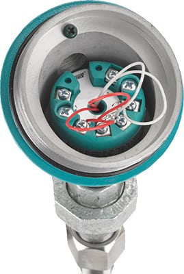
Figure 1. An RTD assembly with a transmitter mounted in the connection head is becoming a popular option, as industry trends indicate a shift away from the use of direct wiring and switches
Process temperature is the most widely used measurement in the chemical process industries (CPI), and is crucial to the efficiency and effectiveness of many processes. Examples of CPI units where process temperature measurement is critical include reactors, distillation columns, evaporators, heat exchangers, boilers, furnaces and more.
The market for process temperature measurement continues to evolve as user industries and technologies change. In recent years, several trends have been observed in the temperature-measurement market, based on newly available technologies, as well as the desire to reduce costs and improve operations. Several of these trends are covered in this article, including the following:
- A decreased reliance on thermocouples (T/Cs) as users shift to thin-film resistance temperature detectors (RTDs)
- A preference for the use of transmitters with RTDs (Figure 1) versus direct wiring
- A shift toward transmitters instead of switches in safety applications
- The increased availability of integrated temperature assemblies
- The widespread adoption of thermowell design according to the standards of the American Society of Mechanical Engineers (ASME; New York, N.Y.; www.asme.org) Performance Test Code (PTC) 19.3 TW-2010
- New products that are designed to solve old problems, such as high-accuracy RTDs used for energy flow or custody transfer, and clamp-on RTDs that are specially designed for use with small pipes and corrosive applications
This article discusses these trends and the impact they have on process-temperature measurement.
Shift to thin-film RTDs
Temperature is the most commonly measured variable in process control, with over $400 million in RTDs and T/Cs sold annually in the U.S. alone, with about 30% of that total being used in the CPI, according to Global Automation Research (Minneapolis, Minn.; www.globalautomationresearch.com). Over the years, the industry has experienced a great deal of evolution in sensors and available physical-construction options. While the options are numerous, the optimum configuration for a particular application is not always clear. However, there continues to be a steady shift toward the use of RTDs in lieu of T/Cs across the board.
Concerns about maintenance, cost and accuracy are the primary drivers in the shift to the use of RTDs from T/Cs. Although, in many cases, T/Cs will have a lower initial cost when compared to RTDs, users may find that the value of the accuracy and stability offered by RTDs exceeds the initial cost savings of installing a T/C. The shift away from thermocouples is also reinforced by a trend toward the use of thin-film RTDs from wire-wound designs, since the cost difference is much less than with wire-wound devices. Additionally, with recent advances in technology, users may find that the benefits of an RTD can be obtained at a lower price premium than in the past.
Still, applications do exist where the use of a T/C makes sense, including those where the process temperature exceeds the limit of an RTD (1,200°F), or when a very fast response is needed. However, there are some fast-response RTD designs available that may also negate the use of T/Cs in the latter case.
Thin-film RTDs are typically limited to temperatures of 500°F, while wire-wound elements can withstand temperatures up to 1,200°F. Also, due to the construction of the sensing element, thin-film RTDs do not perform as well in environments where high levels of vibration or severe mechanical shock occur.
Transmitters versus direct wiring
The majority of process temperature measurements are still wired directly to the control system or to the recorder in use. This is usually done when the controller is relatively inexpensive and is located close to the measurement point. Transmitters can provide functionality without direct wiring, instead interacting with the RTD directly, and there are several benefits to their use with RTDs, detailed in the sections below.
Decreasing wiring costs. Standard 4–20-mA wiring is far less expensive than RTD or T/C wiring. This difference can be verified by calculating the distance of the wire runs and the cost of the T/C wire, and comparing this value with the cost of the standard signal wire plus the transmitter. The cost of three- or four-wire RTD cable makes the decision easier as well, although a four-wire design allows the use of a lighter grade of wire.
Protecting signals from noise and grounding problems. Operating with bad input data can cause off-specification product and increase material and energy usage. Transmitter circuits are designed to minimize the impact of noise that can affect input data. This is particularly useful when the temperature measurement is occurring near electrical equipment that may generate high radio-frequency interference (RFI) or electromotive-force (EMF) levels. The transmitter also provides electrical grounding.
Reducing hardware and stocking costs. Field sensors are connected to the distributed control system (DCS) and programmable logic controller (PLC) via input and output cards. Each input/output (I/O) card has a fixed footprint, so these cards will often limit the number of field-temperature devices that are connected, since they may require up to four wires versus two for standard 4–20-mA devices. The DCS or PLC direct-temperature input card is usually more expensive per point, and sometimes has a lower density (fewer points per card) that can increase the overall I/O cost. Using a universal input transmitter also reduces the variety of transmitters that must be stocked as spares.
Enhancing accuracy and stability. Transmitters can be ranged to only view a narrow span (say, 50 to 250°F), whereas a direct input must be able to process the full range of sensors used. The smaller range also provides better resolution and accuracy.
Simplifying engineering and preventing miswiring.With only standard 4–20-mA input cards on the system, there is less need to group and segregate the temperature inputs. Maintenance of the I/O system is also made easier, and fewer I/O card spares will be needed.
Easing future upgrades. When a temperature instrument has been upgraded from a T/C to an RTD, it is much easier to make the change when only a short run of T/C wire needs to be replaced.
Transmitters versus switches
For safety applications, there is a growing recognition of the value of using a transmitter instead of a switch. This is because a transmitter has a “live zero” functionality, meaning that the 4–20-mA signal range indicates that the unit is working at a 0% output (4 mA). For a switch, the output possibilities are “zero” or “one,” with the “one” value normally indicating that the switch’s trip point has been exceeded. A “zero” output could result from a good measurement or a failed switch. This means that the information supplied by this measurement is less reliable than that provided by a transmitter.
The improved diagnostics available with smart devices make this position even more obvious. Engineers are increasingly using international standards, such as the International Electrical Commission’s (IEC; Geneva, Switzerland; www.iec.ch) IEC 61508, IEC 61511, and the International Society for Automation’s (ISA; Research Triangle Park, N.C.; www.isa.org) ISA S84 for designing their safety systems. Users even have the option to purchase temperature transmitters that have been tested and rated for safety-integrity levels (SIL) 2 or 3, as required for the process. This methodology is recommended.
The Callendar-Van Dusen Equation
The Callendar-Van Dusen (CVD) equation is used to define the relationship between resistance (R) and temperature (T) of platinum RTDs. It is also used in the international standard IEC 60751. For a more accurate relationship, the ITS-90 (International Temperature Scale) published by the International Committee for Weights and Measures is used. For the range from –200 to 0 °C, the CVD equation is as follows:
R(T) = R0[1 + AT + BT2 + C(T − 100)T3]
For the range between 0°C and 661°C, the equation is shown below:
R(T) = R0(1 + AT + BT2)
Originally developed by British physicist Hugh Longbourne Callendar, and refined by M. S. Van Dusen, the CVD equations are used to determine the temperature-resistance behavior for platinum resistance temperature detectors. The CVD coefficients A, B and C are temperature-dependent, and can be determined for a specific RTD by using calibration techniques
in a laboratory.
As an example, the coefficients for a Pt100 resistor (a platinum-constructed, 100-Ω RTD) according to the IEC751 and ITS-90 standards are given below:
• R0 = 100 Ω
• A = 3,908 × 10–3 °C–1
• B = –5,775 × 10–7 °C–2
• C = –4,183 × 10–12 °C–4
Yet another coefficient, α, is a linear parameter defined as the normalized slope between 0 and 100 °C, as shown below:
α = (R100–R0)/100 × R0
For Pt100 RTDs — the most frequently used RTD type — α will be equal to 0.00385, per IEC 60751 calculation standards.
Integrated assemblies
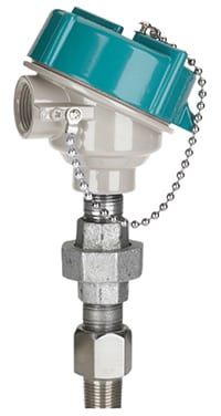
Figure 2. New integrated designs provide a thermowell, RTD, transmitter and local LCD display within a single device
Another trend in the industry is the growing use of integrated assemblies for process temperature measurement. An integrated assembly, as seen in Figure 2, provides a thermowell, RTD, transmitter and local LCD display with a single model number. This reduces costs for both suppliers and users by simplifying order processing and reducing installation costs. With an integrated assembly, the user gets a fully tested system, calibrated to match the sensor.
Thermowell design standards
In 2010, ASME updated its thermowell design standard (ASME PTC 19.3TW-2010) for the first time in many years, in response to numerous reports of failures. The consequences of poor thermowell design can be quite severe, including equipment damage, environmental incidents and loss of life. The new standard can be used for all common well styles — straight, tapered or reduced — and is intended to improve mechanical integrity and help to avoid issues created by excessive vibration, which causes sensor damage. Calculations to meet the new ASME standard should be available from suppliers.
High-accuracy RTDs
RTDs are rated for accuracy according to the IEC 60751 standard. For more details on IEC 60751 accuracy standards for temperature instruments, please see Part 2 of this Feature Report, “Transmitter-Sensor Matching Improves RTD Accuracy” on p. 46. Per IEC 60751, a Class B RTD has an accuracy of±0.3°C, while a Class A RTD has an accuracy of±0.15°C at 0°C. High-accuracy RTDs (what are called Class AA or A+) can have an accuracy as high as±0.03°C, depending on the device and process conditions. Typically, per IEC 60751, Class AA RTDs are rated with an accuracy of 0.1°C at 0°C.
High-accuracy RTDs can be used for several applications where such precision is beneficial, including custody transfer and energy flow. Energy flow, measured in Btu/h, is used to determine the efficiency of heat exchangers and chillers, and is used for advanced control of distillation columns measuring the hot-oil flow in the reboiler and the internal reflux rate of the reflux drum (Figure 3).
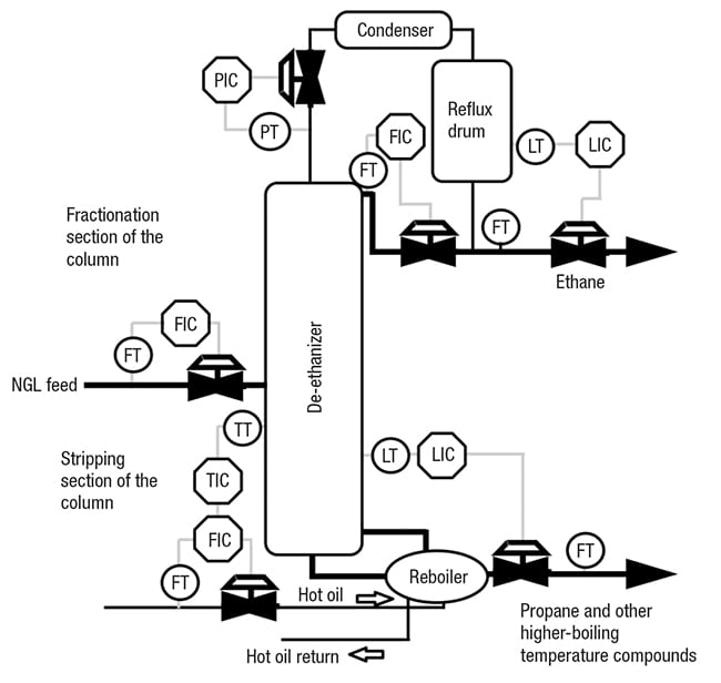
Figure 3. High-accuracy RTDs come in handy for energy-flow applications for the reboiler and reflux drum on a distillation column
When attempting to achieve the ultimate accuracy, the user has two options. First, Callendar-Van Dusen (CVD) data can be used for sensor matching from the RTD (usually a class B) and adjusted for the error in the transmitter (see the box above for more details on CVD calculations.) The second option is simply using a high-accuracy RTD. Several advantages of selecting a high-accuracy RTD are as follows:
- Element selection results in a higher-purity platinum, which provides improved accuracy and stability
- Inherent ability to minimize the effects of self-heating
- The RTD is not married to a particular transmitter. This allows RTD, transmitter and sensor interchangeability
- Reduces downtime
- Eliminates any costs and fees associated with CVD calibration
- Satisfies the need for the best-possible accuracy at the point of measurement
- Improved linearity allows two-point calibration for purposes of recertifying, rather than five points as recommended by CVD
- Provides actual point-to-point accuracy rather than linearization (around three to five temperature points) with the CVD algorithm
Defining the required accuracies using a simple mathematical formula can help to determine whether a Class A or B device will provide the acceptable tolerance. Equations (1) and (2) below provide the definitions for Class B and A, respectively, where temperature ( T) is measured in °C.
Class B: ∆ T =±(0.3 + 0.005 T) ( 1)
Class A: ∆ T =±(0.15 + 0.002 T) ( 2)
For example, using Equation (1) for Class B, the accuracy of the element at 100°C is± 0.8°C. In the range of 0 to 100°C, high-accuracy RTDs improve upon the accuracy of a Class B RTD by an order of magnitude. Therefore, in this range, the Class B formula can be used, with the accuracy value increased by an order of magnitude. Using this method, the accuracy at 100°C would be±0.08°C for a high-accuracy RTD.
Clamp-on RTDs
In processes with small pipes, especially in laboratories or pilot plants, it can be very difficult to obtain an accurate temperature measurement. One solution is to use an external, clamp-on RTD (Figure 4) that is designed specifically to match the outside diameter of the pipe to maintain maximum accuracy. These RTDs can be calibrated to account for the thermal gradient across the pipe wall to attain this high accuracy. Clamp-on RTDs are an acceptable alternative to traditional, inserted RTDs, because they demonstrate very similar behavior with regard to response and accuracy (Figure 5).
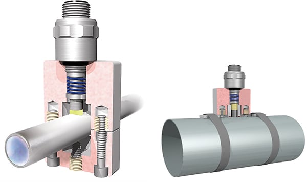
Figure 4. Clamp-on RTDs are useful in applications where very small pipes are required (left), but can also be used with large pipes (right). Clamp-on instruments are also beneficial in applications where the process conditions could be damaging to inserted instrumentation, such as with very corrosive materials
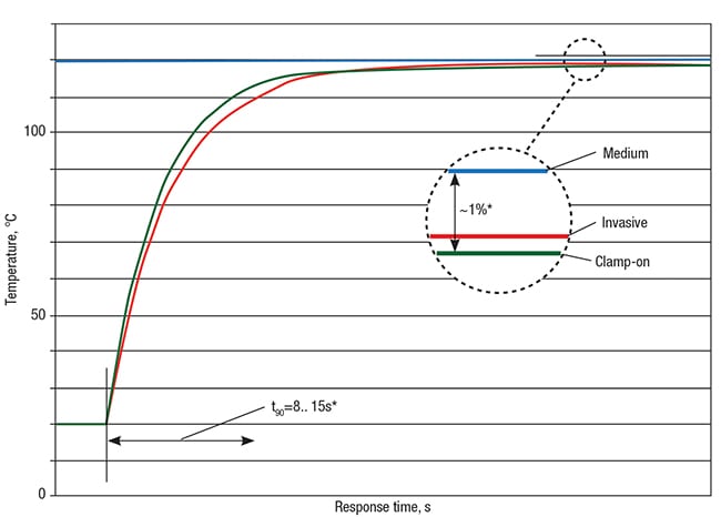
Figure 5. The accuracy and response of the clamp-on RTD compared to an inserted RTD show that they are very close throughout the response, meaning that the clamp-on is an acceptable alternative
The clamp-on approach is also useful when dealing with corrosive chemicals, since the sensing element does not come into contact with the process itself, only the outside of the piping.
Although temperature is among the simplest of the primary process measurements used today, an awareness of the latest options available for temperature measurement can yield significant savings and improvements to processes. ■
Edited by Mary Page Bailey
Author
 Mike Cushing is product marketing manager for Pressure & Temperature Products at Siemens Industry, Inc. (1201 Sumneytown Pike, Spring House, PA 19477; Phone: 267-470-3507; Email: michael.cushing@siemens.com). In this role, Cushing is responsible for product-management, marketing and business-development functions for Siemens’ growing pressure and temperature business. He is a senior member of ISA, has worked on various standards over the years and currently chairs the S77 standards committee on power-plant demand. Cushing has more than 30 years of experience in instrumentation and control systems, having held various positions in engineering, sales, product development and marketing. He has a B.S.Ch.E. from the New Jersey Institute of Technology and an M.B.A. in marketing from Rutgers University.