The Benfield gas-purification process remains a proven and robust technology for CO₂ and acid-gas removal in ammonia synthesis gas (syngas), refinery hydrogen units and petrochemical syngas trains. However, many operating systems are now pushed far beyond their original design capacities, with operational bottlenecks increasingly concentrated in the CO₂ absorption section.
These constraints often manifest as reduced hydraulic capacity, solvent losses, high CO₂ slippage and rising steam consumption. Left unresolved, they increase energy costs, impair downstream conversion efficiency, and elevate the risk of unplanned outages.
This article focuses on one such system — designated Act-1 — in an ammonia facility that had expanded to nearly 40% above its original design capacity. Previous modifications, including packing replacement, increased solution circulation and additional ejectors, could not prevent the following issues:
- Persistent CO₂ breakthrough impacting ammonia and urea production
- Escalating low-pressure steam demand
- Progressive mechanical degradation affecting the reboiler, the flash drum and ejectors, leading to reduced performance and higher maintenance frequency
The site pursued a fully-system revamp with an experienced engineering team. The solution employed simulation-driven diagnostics, hydraulic and mechanical evaluations and fit-for-purpose engineering to resolve root causes, providing a repeatable upgrade methodology for Benfield CO₂ systems in high-demand industrial environments.
Background and system history
The ammonia facility was commissioned in 1992 with a nameplate capacity of 1,500 metric tons per day (m.t./d). Subsequent debottlenecking projects in 1997 and 2009 increased output to 2,125 m.t./d. However, the Benfield CO₂ removal system was never proportionally upgraded. Core hydraulic and thermal designs remained unchanged, and only selective modifications were implemented. Figure 1 shows the system configuration after the 2009 expansion.
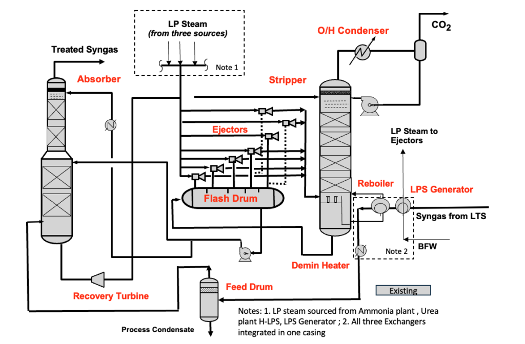
FIGURE 1. Pre-revamp Benfield system
Incremental modifications over the years
To accommodate steadily increasing plant throughput, a series of performance enhancements were introduced at different stages:
- Replaced random packing in the absorber with high-capacity metal tower packing to reduce flooding risk
- Added supplementary ejectors in the fourth and fifth flash drum compartments
- Installed chevron trays in the stripper overhead to minimize water and solvent carryover
- Upgraded the stripper overhead condenser and reflux system
- Modified the CO₂ knockout vessel
- Increased Benfield solution circulation rate by around 17%
- Increased potassium carbonate (around 7%) and activator (around 50%) concentrations
- Added low-pressure (LP) steam injection to both the stripper and ejectors
While these measures provided temporary relief, they could not compensate for the underlying hydraulic, thermal and mechanical constraints of the original design. Under sustained high loading, system performance continued to decline — ultimately making a comprehensive, system-wide revamp unavoidable.
Pre-revamp operating challenges
By the time the revamp engineering team was engaged, the CO₂ removal system faced persistent constraints that eroded energy efficiency, mechanical reliability and production capacity, described below.
High CO₂ slippage. Breakthrough levels reached up to 4,200 ppmv versus a design limit of 1,000 ppmv, increasing synthesis loop inerts, raising purge rates and lowering ammonia conversion. This, in turn, curtailed urea production potential
Hydraulic instability. Characterized by frequent pressure-drop excursions and near-flooding in the absorber and stripper — indicated severe capacity limits and poor vapor–liquid distribution
Elevated LP steam demand. Resulting in overfiring of auxiliary boilers, excess steam venting in the urea unit, increased cooling and deminerlized water use, and inefficient deaerator operation, all driving up utility costs
Feed separator overload. Higher feed temperatures and flows led to solvent carryover and exchanger fouling downstream
Undersized flash drum and ejector inefficiency. Constraining stripping performance and limiting hydraulic flexibility.
Thermal inefficiencies. Fouled heat-transfer surfaces and restricted flow in the reboiler loop reduced thermal performance
Progressive mechanical degradation. Deterioration of ejectors, flash drums, and reboilers increased maintenance frequency and risk of unplanned shutdowns
Collectively, these issues compromised reliability, increased energy consumption and created sustained bottlenecks across downstream units during high-throughput operations.
Revamp approach
To address persistent hydraulic, thermal, and reliability constraints, the revamp engineering team developed and executed a two-phase revamp strategy in close collaboration with the plant’s engineering and operations teams. The plan combined validated process simulation, cost–benefit analysis and targeted process design with execution by an EPC contractor following the process design package (PDP).
Phase 1 — Simulation, diagnostics and assessment
- Validated process simulation models — Calibrated to actual operating data under varying loads, enabling accurate bottleneck diagnosis and post-revamp performance forecasting.
- System evaluation — Hydraulic, thermal, and mechanical assessments of absorber, stripper, flash drum, ejectors and reboiler circuits, including heat-duty analysis and equipment condition checks.
- Cost-benefit screening — Upgrade scenarios evaluated for technical impact, feasibility, and ROI, factoring in layout constraints and vendor input.
- Plant owner concurrence — Final scope agreed jointly with plant engineering and operations to align with priorities and budget.
Phase 2 — PDP
- Defined upgrades and optimized operating parameters, including:
- Revised flash drum sizing and configuration
- Specifications for new ejectors, reboiler, and column internals
- Recommended setpoints for high-load operation
- Formed the technical basis for procurement, budgeting, and layout planning.
Following development of the PDP, the plant owner engaged an EPC firm for detailed engineering, procurement, and installation. Commissioned in mid-2022, the upgraded CO₂ removal system restored hydraulic stability, reduced CO₂ slippage, improved energy efficiency and enabled reliable, sustained high-throughput operation.
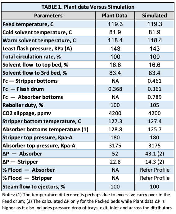
Plant data versus simulation
The engineering team developed a detailed simulation model of the Benfield CO₂ removal system using a rigorous, rate-based framework. Actual plant operating data, including flowrates, temperatures, pressures, CO₂ loading, solvent composition and utility usage, were integrated with original design documentation and field-verified equipment configurations. Special care was taken to accurately represent the installed column internals, including specific packing types and hydraulic capacities in both the absorber and stripper.
The model was calibrated to match observed behavior under high-throughput operation and validated against historical operating records. Key parameters, such as CO₂ removal efficiency, pressure drop, steam usage and liquid distribution, showed strong agreement between simulation predictions and actual plant performance. This confirmed the model’s reliability as a decision-making tool for targeted upgrades.
Table 1 presents a comparison of simulated and observed performance metrics.
Once validated, the model was used for targeted parametric studies to assess the impact of changes in:
- Circulation rate
- Packing configuration
- Steam flow distribution
- Ejector performance under elevated loads
These studies quantified the technical benefit and feasibility of each potential modification, considering hydraulic limits and integration constraints.
Figure 2 summarizes the predicted effects on CO₂ slippage, column pressure drops and steam consumption. The insights from these simulations formed a data-driven foundation for final equipment selection and operating strategy during the revamp design phase.
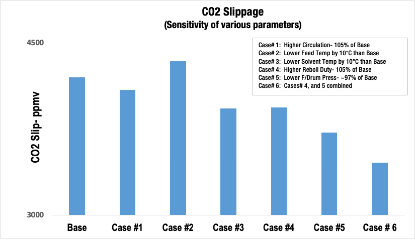
FIGURE 2. CO2 slippage (sensitivity of various parameters)
Key findings
The Phase 1 study, conducted under base (normal) operating conditions, identified the following issues and improvement opportunities across the Benfield CO₂ removal system.
Overall equipment loading
Nearly all major components operated at or above original design limits. Hydraulic constraints in the absorber and stripper columns significantly impaired vapor–liquid distribution, column efficiency and overall system performance.
Absorber column
Flooding conditions — Beds #2 and #4 operated close to hydraulic limits (~98% capacity, Figure 2A), risking incipient flooding.
Liquid distributors — The liquid distributors in the lower two beds were under-rated and likely overflowing, reducing efficiency. Upper distributors, while near design capacity, had low drip density and poor liquid distribution. Figure 3 shows that the lower distributors are operating at more than 125% of their rated capacity; the upper distributors are nearing their maximum limits.
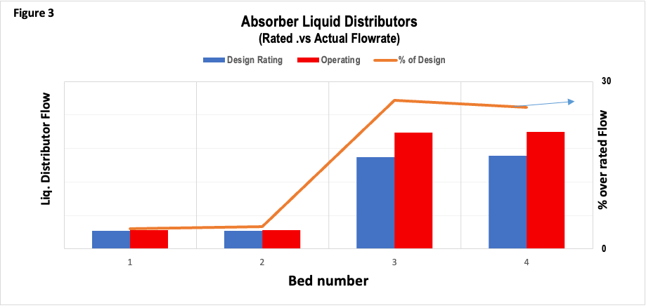
FIGURE 3. Absorber liquid distributors (rated versus actual flowrate)
Vapor distribution – Excessive vapor velocity through the feed nozzle into Bed #4 caused maldistribution. Two installation options for a new vapor distributor were assessed: (1) Hot-work installation during turnaround (TAR) — technically preferred but outage-dependent. (2) External installation with Bed #4 shortened/raised by around 1 m — less desirable due to loss of manway access.
Stripper column
Flooding conditions — Bed #4 operated at around 94% flood capacity (Figure 4).
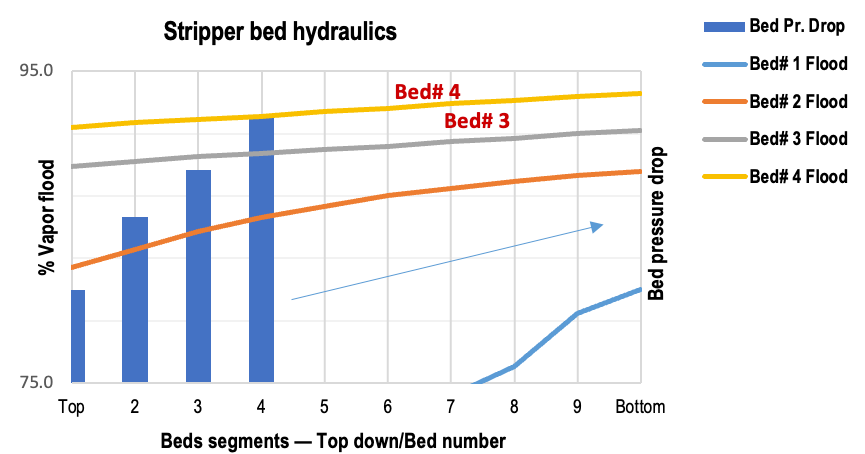
FIGURE 4. Stripper bed hydraulics
Liquid distributors — All four distributors operated above 140% of their rated capacity (Figure 5), resulting in poor liquid distribution and degraded performance.
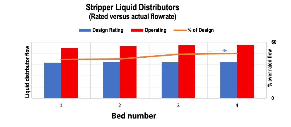
FIGURE 5. Stripper liquid distributors (rated versus actual flowrate)
Vapor distribution — Two vapor distributors are recommended; the feasibility of hot-work installation for TAR is to be confirmed.
Reboiler circuit — The liquid level in the reboiler could be increased by modifying the bottom chimney tray collector box (TAR hot work required).
Wash trays — Likely operating in a spray regime due to low liquid rates, which risks carryover. Action: Redirected cold condensate makeup from the reboiler vapor line to the wash trays to improve liquid loading.
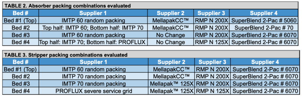
Packing evaluation
The engineering team independently evaluated multiple packing configurations for both columns (Tables 2 and 3) using the validated Benfield simulation model. Recommendation: Retain the existing packings; defer the replacement decision until post-revamp validation of the upgraded vapor and liquid distributors. Key observations: (1) 4th-generation random packings offered better hydraulics but increased CO₂ slippage. (2) Structured packings showed potential for improved hydraulics and CO₂ removal efficiency, but performance under high liquid load remains uncertain with limited full-scale validation.
Flash drum and ejector system
Existing issues — The flash drum showed cracks in its internals/welds; several ejectors exhibited wear and declining efficiency. The drum is undersized, with inadequate vapor disengagement and residence time.
New design — Replacement drum around 160% larger, retaining original five-compartment layout to minimize piping changes. One ejector per compartment, designed for existing LP steam conditions.
Sensitivity analysis (Figures 6 and 7) revealed that higher steam pressure significantly reduced steam consumption, whereas steam superheat had a minimal effect on steam use.
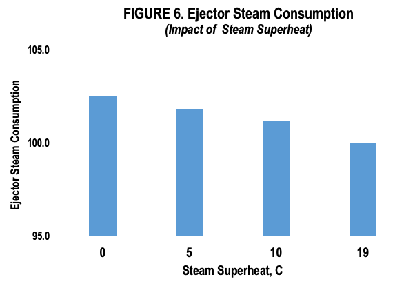
FIGURE 6. Ejector steam consumption (impact of steam superheat)
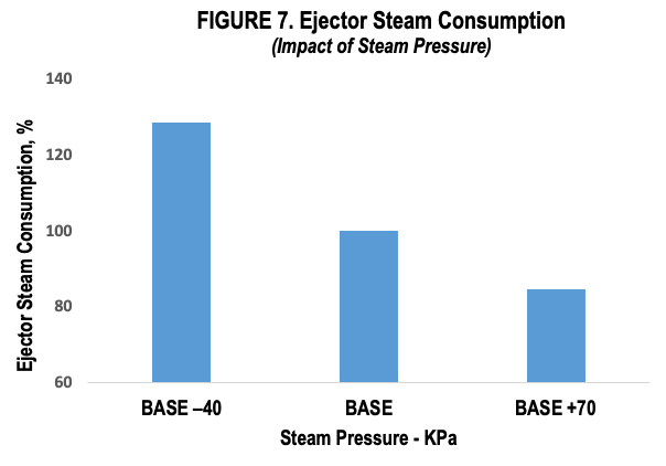
FIGURE 7. Ejector steam consumption (impact of steam pressure)
Stripper reboiler replacement
Rationale — Severe tube wall thinning posed reliability and mechanical integrity risks.
New Design — Higher-duty reboiler to increase CO₂ stripping capacity and improve thermosiphon circulation, fitting within existing space/piping limits. A longer tube bundle can be accommodated without requiring layout changes.
Benefits — Reduced steam demand, lowering auxiliary boiler load and greenhouse gas emissions. Lower heat load on the demineralized water heater improved deaerator stability.
Recovery turbine
Already at full capacity with the largest impeller in place. Recovering around 225 kW of additional power would require significant modifications, including the relocation of the pump. A cost–benefit analysis deemed the upgrade unjustified.
Separators
The absorber feed separator is significantly undersized, causing excessive vapor velocity and liquid carryover. The stripper overhead separator and treated syngas separator are adequately sized for the current loads.
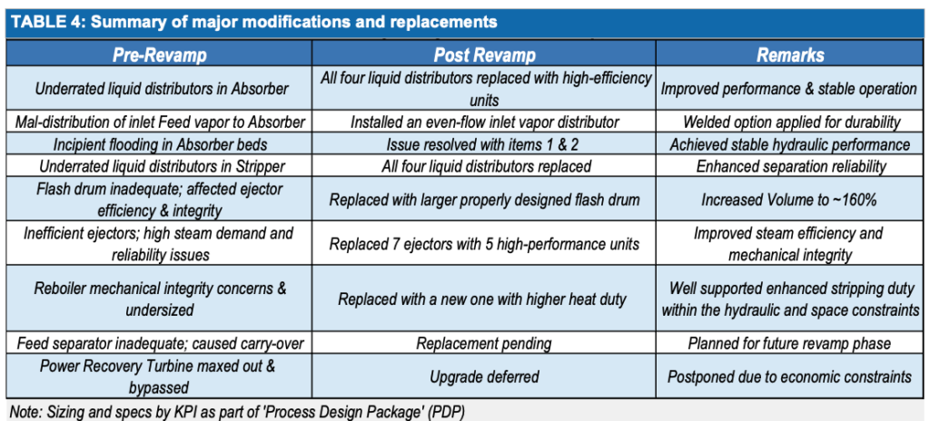
Key modifications and justifications
A comprehensive revamp was executed to address the hydraulic constraints, reliability risks and energy inefficiencies identified during the Phase 1 assessment. The major upgrades introduced in the 2022 revamp are outlined in Table 4 and reflected in the post-revamp process flow diagram shown in Figure 8.
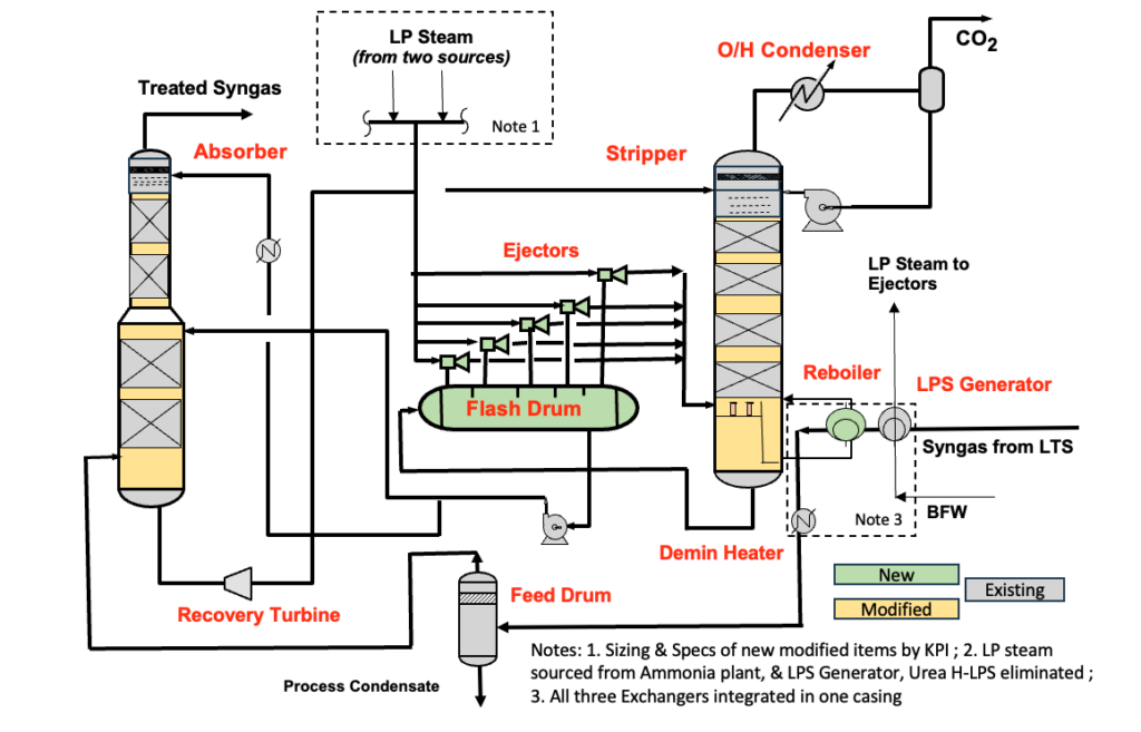
FIGURE 8. Post-revamp Benfield system
Absorber vapor distributor
- Issue: Maldistribution and excessive inlet vapor velocity at the feed nozzle resulted in poor contact with the lower bed and localized flooding.
- Solution: A vane-type vapor distributor was installed to ensure even vapor entry across the column cross-section.
- Impact: Improved vapor distribution enhanced mass transfer efficiency, reduced CO₂ slippage, and mitigated localized flooding risks.
Absorber liquid distributors
- Issue: All four distributors were significantly overloaded, operating beyond their hydraulic rating, which caused uneven wetting and compromised bed performance.
- Solution: Replaced with high-capacity orifice-deck distributors designed to handle increased circulation rates and provide uniform liquid loading.
- Impact: Improved column efficiency, stabilized hydraulic performance, and restored reliable absorber operation.
Stripper liquid distributors
- Issue: Severe maldistribution due to under-rated liquid distributors constrained column separation performance.
- Solution: All four distributors were upgraded to high-efficiency designs suited for current liquid flow requirements.
- Impact: Ensured uniform wetting, improved CO₂ stripping, and reduced variability in product gas quality.
Flash drum replacement
- Issue: The existing flash drum was undersized and mechanically degraded, limiting vapor disengagement and reducing ejector suction stability.
- Solution: Installed a new vessel with 160% of the original volume, while retaining the five-compartment layout to simplify tie-ins.
- Impact: Enhanced vapor-liquid separation, improved ejector reliability, and reduced entrainment into downstream equipment.
Ejector system optimization
- Issue: The original seven ejectors showed declining performance and elevated steam consumption due to age and wear.
- Solution: Replaced with five modern high-efficiency ejectors optimized for the available low-pressure (LP) steam conditions.
- Impact: Lowered motive steam demand, eliminated reliance on higher LP steam headers, and reduced venting in downstream urea operations.
Stripper reboiler upgrade
- Issue: Tube thinning and reduced heat transfer in the existing reboiler posed a reliability risk and limited stripping efficiency.
- Solution: A higher-duty reboiler was installed, sized to fit within the original footprint and piping envelope.
- Impact: Improved CO₂ stripping capacity, reduced LP steam consumption, and enhanced thermal stability, contributing to lower emissions and improved ammonia synthesis loop efficiency.
Feed separator (planned upgrade)
- Issue: The Absorber feed separator was undersized, leading to carryover of liquid droplets and impacting column hydraulics.
- Solution: Replacement is scheduled for a future phase to match current feed conditions.
- Justification: Enhancing disengagement capacity is critical to protecting absorber performance and minimizing solvent losses.
Power recovery turbine (deferred)
- Issue: The existing turbine had reached its capacity limit, with no further impeller upgrades possible.
- Solution: Upgrade was deferred due to the need for extensive piping and pump relocation.
- Justification: Economic evaluation concluded that the estimated 225 kW power recovery did not justify the associated capital expenditure.
Table 4 provides a consolidated summary linking each pre-revamp issue to its respective solution, including the operational benefits realized post-implementation.
The simulation-driven revamp delivered lasting performance improvements, with the calibrated process model pinpointing critical upgrades and supporting a thorough cost–benefit assessment during the design phase.
Key improvements realized
- CO₂ Slippage Reduction — CO₂ breakthrough decreased by approximately 1,500 ppmv (Figure 4B), improving synthesis loop composition and ammonia conversion efficiency. This directly enabled incremental ammonia and urea production, with the plant achieving record, stable output post-revamp.
- Restored Hydraulic Stability — Upgraded vapor and liquid distributors eliminated incipient flooding in both absorber and stripper columns. The absorber now operates stably with no differential pressure excursions, even at elevated throughput.
- Utility Efficiency Gains — Reduced high-to-low-pressure (H–LP) steam consumption, curtailed auxiliary boiler firing, and eliminated steam venting in the urea section, improving overall energy utilization and lowering operating costs.
- Enhanced Mechanical Integrity — Replacement of the flash drum, ejectors, and reboiler addressed known deficiencies and improved long-term reliability. Maintenance intervals are extended, and the risk of mechanical failure has been significantly reduced.
Table 5 summarizes the key post-revamp operating metrics, confirming improved energy efficiency, stable throughput and enhanced reliability following the mid-2022 startup.
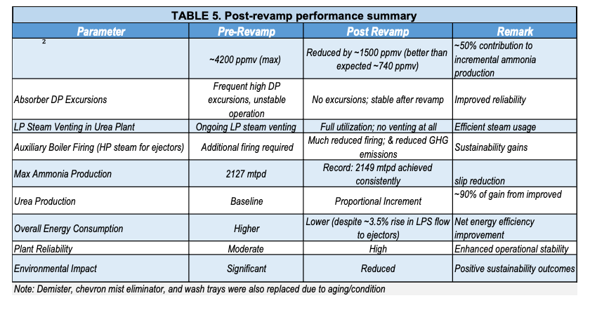
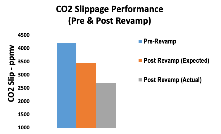
FIGURE 9. CO2 slippage performance (pre- and post-revamp)
Conclusion
The revamp of the Act-1 Benfield CO₂ system demonstrates how a structured, simulation-driven approach can deliver lasting improvements in performance. By combining validated process models with detailed hydraulic and mechanical evaluations, the engineering team was able to pinpoint root causes rather than rely on incremental fixes. This enabled a revamp that reduced CO₂ breakthrough, cut steam demand, and stabilized key equipment operation.
Beyond this ammonia case, the methodology illustrates how digital tools and fit-for-purpose engineering can modernize aging Benfield units across refineries, petrochemical complexes, and gas-processing facilities. The result is higher throughput, lower energy intensity and sustained reliability —key outcomes for plants operating under growing capacity, cost and emissions pressures. ♦
Edited by Mary Page Bailey
Acknowledgement
All images provided by author
References
- Cost-Effective Revamp of CO₂ Removal Systems in Ammonia Plants, Presented at the Nitrogen + Syngas Conference, London, United Kingdom, March 2017.
- Benfield System Revamp Experience at Yara Plant, Presented at the Nitrogen + Syngas Conference, Barcelona, Spain, March 2023.
Author
 V.K. Arora, P.E., leads Kinetics Process Improvements Inc. (KPI; 16000 Park Ten Place, Suite 903, Houston, TX 77084; Email: vka@kpieng.com; Phone: 281-773-1629; Website: kpieng.net). Arora is a chemical engineer with over 35 years of experience delivering value-driven, practical, and economical process solutions across petrochemical, refining, and syngas facilities. A Texas-licensed professional engineer and IIT Delhi graduate, he has guided KPI for more than 20 years, specializing in high-return brownfield revamps, debottlenecking, and techno-economic feasibility studies. His work spans ethylene plants, propane dehydrogenation, acrylic acid and esters, ammonia and methanol facilities, and integrated low-carbon process solutions. He holds four ammonia process patents and has held senior leadership roles at the following companies: Lummus Technology, KBR Inc., Saudi Basic Industries Corp.(SABIC), Reliance Industries and Technip.