Switching from one fluid to another in a heat transfer system requires an engineering evaluation. Here is what to include
In well-designed and well-maintained heat transfer systems, heat transfer fluids generally last for a long time and function as intended. However, there are situations in which it is necessary to change heat transfer fluids. When a switch in fluids is required, facilities in the chemical process industries (CPI) should pay careful attention to a number of important considerations surrounding the properties of the old and new fluids, as well as the design of the heat transfer system. This article provides information about conducting an engineering evaluation to determine how the fluid change will affect safety, environmental concerns, system maintenance and process performance.
Heat transfer system operation
Steam is often used for process heating. Primarily, steam transfers heat when it condenses. To transfer heat at high temperature, the steam pressure must be very high. For example, 600-psig steam condenses at approximately 490°F, but many processes require heating to higher temperatures than that. For these applications, a heat transfer fluid can be used. Heat transfer fluids are sometimes referred to as thermal fluids or hot oils.
Heat transfer fluids have a much lower vapor pressure than water, so they require a much lower operating pressure at a given temperature. Also, a heat transfer fluid system can be designed to provide both heating and cooling to a process, if required.
Some systems are designed to use heat transfer fluid in the vapor phase, but most systems use heat transfer fluid in the liquid phase. A typical liquid-phase heat transfer fluid system, as shown in Figure 1, includes a heater, a pump to circulate fluid through the heater to the process, an expansion tank to accommodate thermal expansion of the fluid, and one or more process heat exchangers. Subloop pumps may be used to circulate fluid through process heat exchangers. Sometimes subloops are operated at a lower temperature than the main circulating loop, and fluid from the main loop is only added as needed to maintain the desired operating temperature. System volume can vary from a few gallons for a pilot-scale system to over 100,000 gallons for a large-system with multiple heaters.
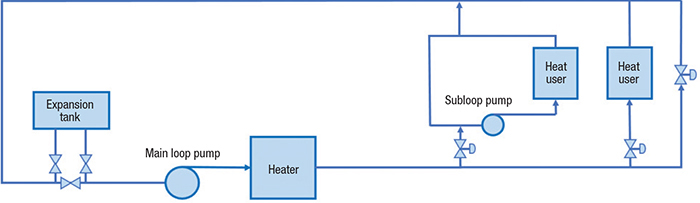
Figure 1. This process diagram shows a typical liquid-phase heat transfer fluid system
Heat transfer fluids degrade over time when operated at high temperature. Thermal degradation products include low-boiling components, high-boiling components and sludges. In a well-designed and well-maintained system, the fluid should last for many years. The condition of the fluid should be routinely monitored to assess when fluid maintenance is needed.
Considering a fluid change
Plant owners with a heat transfer fluid system may decide to switch fluids for several reasons, including the ones listed here:
Rapid performance degradation. The current fluid performance has degraded too quickly at the current operating temperature. There may be fouling of heat exchangers by high-boiling solids in the degraded fluid, which can reduce heat transfer to the process. A significant level of low-boiling components in the degraded fluid may be accumulating in the heat exchangers, which can reduce heat transfer to the process. Similarly, accumulation in pumps can reduce pump output. These problems can limit production rate.
Need higher temperature. The owner may be planning to increase the system operating temperature to increase heat transfer to the process, and the current fluid will degrade too quickly at the higher temperature.
System-fluid mismatch. The owner has discovered a mismatch between the system design and the current fluid. As an example, the author has seen a system where the selected fluid’s vapor pressure at operating temperature was higher than the pressure rating of the expansion tank and some other components, so fluid was continuously being vented out of the system.
Cost considerations. The owner may be trying to reduce cost. However, the ongoing cost to add fluid to the system must be considered, as well as the initial fill cost. A fluid that is more resistant to thermal degradation will have lower ongoing cost for makeup fluid, and fewer issues with fluid degradation products.
Supplier technical support. The owner may need a more extensive level of technical support from the fluid supplier. The owner can benefit from an experienced fluid supplier with deep knowledge of fluid chemistry who can provide detailed information about why the fluid condition is changing and make practical recommendations about what actions are needed. In the event of fluid contamination, an experienced supplier can evaluate the impact and help the owner determine what actions to take.
Comparing fluids
The most common high-temperature heat transfer fluids are synthetic organic fluids, mineral oils and silicone-based fluids. Most heat transfer fluids have unique chemistries, so their physical properties are different. Because fluids have different physical properties, it is always appropriate to do an engineering evaluation to determine how the fluid change will affect safety requirements, environmental requirements, operation and maintenance of the system. The engineering evaluation should include all of the factors described below.
Fluid temperature ratings. Heat transfer fluids have maximum bulk-temperature and maximum film-temperature ratings that vary by chemistry and are determined by the fluid supplier. Bulk temperature is the temperature that the majority of the fluid experiences. Film temperature is the temperature experienced by the film layer in contact with the heater tubes or heating element as heat is transferred into the fluid. Film temperatures are higher than bulk temperatures, so the thermal degradation rate experienced by the fluid’s film layer is higher.
The volume of the film layer is small compared to total system volume. For systems with a well-designed heater operating at or below its design capacity, the amount of thermal degradation experienced by the film layer will be a small portion of the thermal degradation of the total system.
The heater should be designed for fully turbulent flow inside the tubes or across the heating element. This increases the heat transfer coefficient and decreases fluid film temperature and film thickness. A more conservatively designed heater will result in a smaller difference between the fluid film temperature and the bulk temperature, as illustrated in Figure 2.
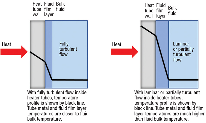
Figure 2. The black line represents the heat transfer fluid’s temperature profile inside the heater tubes
There is no single, universal approach to determine fluid temperature ratings, so some suppliers may be more conservative with their ratings than others. Each supplier can explain how its fluid temperature ratings were determined. Thermal stability (the resistance to permanent changes in properties caused solely by heat) must be considered in determining fluid temperature ratings, since it strongly influences the life of the fluid. Thermal stability of fluids can be measured using ASTM test method D6743, the Standard Test Method for Thermal Stability of Organic Heat Transfer Fluids, which quantifies the amount of thermal degradation that the fluid experiences at a given temperature and time period. At its maximum bulk-temperature rating and maximum film-temperature rating, a fluid should have a thermal degradation rate that is sufficiently low that the fluid will last for many years.
In general, the selected fluid should have a bulk-temperature rating equal to or higher than the highest operating temperature of the system. Also, the fluid’s film temperature rating should be equal to or higher than the highest film temperature that will occur in the heater. Film temperature is a function of the heater heat flux (heat transferred per unit area), as well as the fluid properties (which affect the heat transfer coefficient of the fluid). Film temperature is directly proportional to heat flux. Given the same fluid flowrate through the heater, an increase in heat flux (by increasing the firing rate of the heater) will result in an increase in film temperature. Film temperature is inversely proportional to the heat-transfer coefficient of the fluid film. Given the same flowrate through the heater and same firing rate, a new fluid with higher heat-transfer-film coefficient than the old fluid will experience a lower film temperature.
Fluid heat transfer properties. The effectiveness with which heat is transferred from the heat transfer fluid to the process is expressed by overall heat transfer coefficient. Equation (1) describes the heat transfer through a wall.
U = 1/hP + L/k + 1/hHTF (1)
Where:
U is the overall heat transfer coefficient
hP is the process-fluid-film heat transfer coefficient
L is the thickness of wall
k is the thermal conductivity of wall material
hHTF is the heat transfer coefficient for the fluid film
The properties of the process fluid and heat transfer fluid influence the overall heat transfer coefficient. In some situations, the process side may dominate the overall heat transfer coefficient. In other situations, the heat transfer fluid side may dominate the overall heat transfer coefficient — in these instances, it is important to evaluate how changing the heat transfer fluid affects overall heat transfer coefficient.
The Sieder-Tate equation (Equation (2)) can be used to calculate the fluid-film heat transfer coefficient using fluid properties.
hD/k = 0.022 (DG/u)0.8 (cpu/k)0.4 (u/uw)0.16 (2)
Where:
h is the fluid-film heat transfer coefficient
D is the inside diameter of pipe
G is the mass velocity
k is the thermal conductivity at fluid bulk temperature
p is the density at fluid bulk temperature
cp is the specific heat at fluid bulk temperature
u is the absolute viscosity at fluid bulk temperature
uw is the absolute viscosity at fluid film temperature
The equation can be solved for the fluid-film heat transfer coefficient h:
h = 0.022 (k/D) (DG/u)0.8 (cpu/k)0.4 (u/uw)0.16
The terms can be regrouped in this manner, assuming that (u/uw)0.16 is equal to 1:
h = 0.022 (D)–0.2 (G)0.8 (p)0.8 (cp)0.4 (k)0.6 (u)–0.4
Therefore, the ratio of fluid-film heat transfer coefficients for two heat transfer fluids is proportional to the ratio of their mass velocities, densities, specific heats, thermal conductivities and absolute viscosities raised to the appropriate exponent.
For heat exchangers where the heat-transfer-fluid side significantly influences the overall heat transfer coefficient, heat transfer to the process will be reduced if the new fluid has a lower heat transfer film coefficient than the existing fluid.
Fluid thermal expansion. Heat transfer fluids have a high coefficient of thermal expansion. Therefore, expansion tanks must have sufficient capacity to safely absorb the volume increase that the fluid experiences as it changes from the lowest temperature, when the system is down, to the highest operating temperature. It is good engineering practice to size the expansion tank to accommodate two times the volume change due to thermal expansion. Some systems utilize a smaller expansion tank located at the highest elevation of the system along with a larger overflow tank located at ground level. The combined capacity of these two tanks needs to be large enough to accommodate the thermal expansion of the fluid.
The amount of thermal expansion should be calculated for both the current fluid and for the new fluid. If the amount of thermal expansion for the new fluid is more than the amount for the old fluid, then expansion tank capacity must be checked to make sure that it is sufficiently large.
To minimize oxidation of the heat transfer fluid due to contact with air, the expansion tank should have an inert gas blanket. Oxidation will shorten the life of the fluid.
Fluid vapor pressure. A liquid heat transfer fluid system must operate at a pressure higher than the vapor pressure of the fluid at the operating temperature. Otherwise, some of the fluid will flash to vapor. The presence of vapor will cause pump problems and inhibit heat transfer. Low-pressure points in the system include the suction of the main loop circulating pumps, as well as the areas downstream of control valves that regulate flow from the main loop into subloops.
The expansion tank is typically connected to the return header just upstream of the circulating pumps for the main loop. The pressure of the inert gas blanket on the expansion tank can be set high enough to keep the system operating pressure above the fluid vapor pressure.
If the vapor pressure of the new fluid is higher than the vapor pressure of the old fluid, then the design pressure of system components must be checked to verify that all components can handle the higher operating pressure. In all cases, the sizing and setpoints of relief valves must be checked to determine if they are adequate for the new fluid.
Pump capacity and net positive suction head. If the new fluid has higher density than the old fluid at the operating temperature, then it will require more energy to pump it. The pump supplier should be consulted to verify that the existing pumps and drives will perform adequately with the new fluid. In some cases, a larger drive may be required.
The pressure of the inert gas blanket in the expansion tank should also be set high enough to provide adequate net positive suction head for the main loop circulating pumps. Net positive suction head required (NPSHR) versus pump flowrate is typically shown on the pump performance curve.
Net positive suction head available (NPSHA) can be calculated using this formula: NPSHA = expansion tank pressure – vapor pressure of the fluid at the operating temperature + static head between the expansion tank level and the centerline of the pump – pump suction piping losses.
NPSHA must be higher than NPSHR, or cavitation will occur and cause damage to the pump.
Pumpability. At low ambient temperature, the viscosity of any heat transfer fluid increases, so it is more difficult to pump. If the new fluid has higher viscosity at low ambient temperature than the old fluid, then pumping it at low temperature will be more challenging. Heat tracing can be installed on pump suction piping to help warm the fluid. Also, pumps can be started with the discharge valve partially closed to prevent overloading the pump motor.
Some heat-transfer fluids solidify at ambient temperature. For these systems, heat tracing is needed to prevent solidification of the fluid inside transfer lines when flow is stagnant.
Fluid safety properties. Several properties can characterize the flammability hazard of a heat transfer fluid. Data on flashpoint, fire point and autoignition temperature are typically published by the heat transfer fluid supplier.
It is common for a heat transfer fluid system to have an operating temperature higher than the fluid flashpoint. The flashpoint is the lowest temperature at which an ignition source causes the vapors of the test sample to ignite under the specified test conditions. Examples of flashpoint laboratory tests are ASTM D92, which uses the Cleveland open-cup test apparatus, and ASTM D93, which uses the Pensky-Martens closed-cup testing apparatus.
Since flashpoint values are a function of the test apparatus design and test procedure, open-cup values should not be compared to closed-cup values. ASTM D92 also measures fire point, which is the lowest temperature at which the application of an ignition source causes the vapors of the test specimen to ignite and sustain burning for a minimum of five seconds under specified test conditions.
The operating temperature of the heat transfer fluid system should always be below the fluid autoignition temperature. Autoignition temperature is the minimum temperature at which autoignition occurs under the specified test conditions. ASTM E659 and DIN 51794 are test methods that measure the autoignition temperature of a fluid. The autoignition temperature of the new fluid should be higher than the highest operating temperature of the system.
Fluid initial boiling point. Heat transfer fluid systems should be designed to be leak-tight. It is good practice to avoid threaded piping connections and to minimize the number of flanges used. If a heat transfer fluid is heated to a temperature above its initial boiling point at atmospheric pressure, then accidentally leaked fluid will form some vapor and a mist cloud could result. If the new fluid will be heated to a temperature above its initial boiling point at atmospheric pressure, then plans for dealing with an accidental leak should be developed.
Environmental considerations. Used heat transfer fluids must be disposed of in accordance with local regulations. In the U.S., used heat transfer fluids are regulated by the Environmental Protection Agency (EPA; www.epa.gov) in 40 CFR part 279: Standards for the Management of Used Oil, which requires spill containment, a spill response plan and training. If leaked, some fluids have a spill reporting requirement. The heat transfer fluid Safety Data Sheet (SDS) should include information on accidental release measures, handling, personnel exposure and toxicity. The SDS for the fluid should be reviewed to ensure that adequate plans for containment, response, training and reporting are in place.
Implementing a fluid change
After the engineering evaluation has been completed, a plan for removing the old fluid, flushing the system, and filling with new fluid should be developed. A knowledgeable heat transfer fluid supplier will be able to help the owner develop this plan.
The old heat transfer fluid should be drained completely from the system through drain valves at low points in the system. Pressurized nitrogen may be used to help push fluid to the low points. If drains are not already in place at the low points, they will need to be installed.
After the system has been drained, the system can be filled with flushing fluid, which acts as a solvent to help remove thicker deposits of old fluid that may not have completely drained from the system. The flushing fluid should be compatible with all system components. The flushing fluid is typically heated and circulated throughout the system to remove deposits.
Chemical cleaning can be considered as an alternative to the flushing fluid. However, chemical cleaning is typically more expensive, and multiple flushes required during the cleaning process will generate more waste that must be disposed of.
After the flushing fluid has been drained, the system can be filled with the new fluid. If the system does not already have a side-stream filter installed, consider installing one to remove solids during operation of the system. Startup of the system with new fluid should include holding at about 220°F for several hours while circulating through the expansion tank to allow venting of moisture from the system. A blanket gas purge during the venting process can help greatly.
It is valuable to have a monitoring program to track the condition of the heat transfer fluid. Tracking key fluid parameters with trend analysis can detect changes in fluid condition before they become a problem. A monitoring program allows the fluid supplier to provide timely, practical recommendations for comprehensive maintenance for the heat transfer fluid system, so the owner can plan ahead to minimize the potential for an issue that might cause production downtime.
Edited by Scott Jenkins
Disclaimer
Although the information and recommendations set forth here are presented in good faith and believed to be correct, neither Eastman, nor any of its affiliates, makes any representations or warranties as to the completeness or accuracy thereof. Information is supplied upon the condition that the persons receiving same will make their own determination as to its suitability for their purposes prior to use. In no event will Eastman, or its subsidiaries, be responsible for damages of any nature whatsoever resulting from the use of or reliance upon this information. Nothing contained herein is to be construed as a recommendation to use any product, process, equipment or formulation.
Author
 Gerald E. Guffey II is a senior associate engineer in the Worldwide Engineering and Construction Division of Eastman Chemical Co. (100 North Eastman Road, Kingsport, TN 37660; Phone: 423-229-1095; Email: gguffey@eastman.com). He has been involved in design and evaluation of heat transfer fluid systems and fired heaters for more than twenty years. He has been involved in the development of standards for heat transfer fluids as an ASTM member since 1997. He holds a bachelor of science degree in mechanical engineering from Georgia Tech.