Some of the many things to consider for the complex task of performing a column revamp are presented in this cover story
Petroleum refineries, chemical-processing plants, natural-gas purification plants and other facilities in the chemical process industries (CPI) all contain columns. These columns perform distillations [1], regenerations, strippings and absorptions. Column diameters range from 12 in. to 50 ft, and column heights range from 10 to 350 ft.
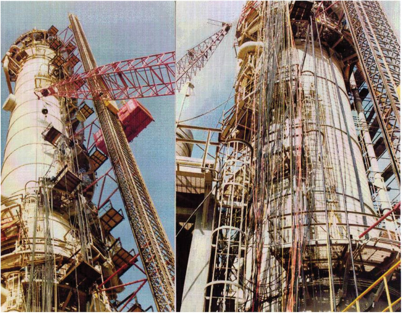
FIGURE 1. Revamping a column is a major undertaking
Prior to about 1970, the majority of the column work performed in the U.S. was the building and installation of new, grass roots, columns. Subsequent to that, the workload shifted, with many existing columns being revamped to achieve performance improvements or maintenance targets. When columns are revamped, some columns are revamped on the outside; some, on the inside (Figure 1); and some, both.
Associated with columns are heat exchangers, reboilers, condensers, receivers, pumps, valves, tanks and instrumentation. Most column revamps necessarily include evaluations and modifications of this ancillary equipment.
Unfortunately for us, no two real column revamps are identical. They are never easy. And column revamps cannot be boiled down to a step-by-step procedure that can be applied to most columns. Instead, this article presents some of the many considerations that are involved in column revamps.
Trays and packings
Today, globally, approximately one half of columns are equipped with trays and the other half contain packings [2]. The packings can be random or structured. For many years, the performance of trays was considered to be more predictable than packing. Around 1980, however, work by Fractionation Research Inc. (FRI; Stillwater, Okla.; www.fri.org), and others, showed that successful packing performance usually hinges on proper liquid distribution above packed beds. At about that same time, sheet-metal structured packing was invented, and such packing sometimes showed advantages over both random packings and trays.
When compared to trays, the biggest advantage attributable to packings is lower pressure drops. This is particularly true with columns that are operating at pressures below atmospheric. As an example, prior to about 1985, most ethylbenzene-styrene vacuum columns were trayed. Many of those columns were soon revamped with structured packings to reduce the pressure drops across the columns, to reduce the bottom temperatures and to reduce renegade polymerization. Generally, the pressure drop across a bed of structured packing is about one-sixth of that across a stack of trays having the same total height.
On the other hand, there are certainly some services where packing seems to be inapplicable. High-pressure distillation columns, where pure products are being targeted, have resisted the packing “revolution.” Trays perform better, and much more predictably, in such columns where the volumetric liquid-to-vapor ratios are high. Regarding such packed columns, some distillation theoreticians contend that the high liquid rates are causing vapor to back-mix downward. Some theoreticians contend that the low surface tensions of the liquid phases cause tiny liquid droplets to be sheared off easily from the downward-flowing liquid films; those droplets are entrained detrimentally upwards in such columns.
Random packings (for instance, Pall rings) are still very viable in many columns. Random packings are easy to install and have low pressure drops. Their optimum performance depends upon the liquid distributors that are feeding the packed beds. Good liquid distribution is also, of course, required with structured packings.
Regardless of the tower internals, fouling is never good. With trays, some parts get plugged up and are no longer capable of passing liquid or vapor. With packings, distributors become plugged and liquid distributions become non-optimum. Structured packings are much more prone to fouling than random packings, because the metal sheets of structured packings are very tightly spaced.
The companies that develop and sell trays and packings have been very successful at improving the performances of those mass-transfer products. Subsequent to about 1960, there have been four generations of trays as follows:
- Crossflow
- Augmented crossflow
- Counterflow
- Cocurrent flow
Generally, each generation had a higher capacity. Some generations exhibit higher efficiencies than others.
Some practitioners divide the history of random packings into four generations. First came Raschig rings and Berl saddles; then, Pall rings and Intalox saddles; then, proprietary rings from several vendors; and then, high-performance rings from several vendors.
Structured packings had the following history:
- Gauze
- Corrugated and textured sheet metal
- High-capacity corrugated and textured sheet metal
High-capacity structured packings generally exhibit about 20% more capacity than “conventional” sheet-metal structured packings, with no loss in efficiency.
All of these new generations of trays, random packings and structured packings have made it easily possible, at times, to make large improvements in column performances with relatively easy column revamps.
Many column revamps include the changing out of the column internals. These change-outs can be divided into the following broad categories:
- Trays replace trays
- Trays replace packing
- Packing replaces packing
- Packing replaces trays
When trays replace packings, it is usually because the packing performance has been disappointing. When packing replaces trays, it is usually in pursuit of reduced pressure drops.
Revamp targets
Some columns are revamped on the outside. Old insulation is removed. The bare tower is sand-blasted, re-painted and then reinsulated. Such work is required to properly address corrosion under insulation (CUI), which is an increasing safety problem with the aged and aging columns of the western world. After painting, some of these columns are left uninsulated. This allows for easy determinations of future metal-thickness losses almost everywhere on the column shell.
Some columns are revamped on the inside, which is the primary topic of this article. The possible targets of such revamps are the following:
- Replacement, in kind, of old, corroded or plugged, internals
- Increased capacity
- Improved separation (better purities, recoveries or both)
- Reduced energy consumption
In some cases, a column’s service (key separation) is changed completely. Such a revamp can prove to be particularly challenging.
A simple replacement of old internals requires that details of those internals are available via drawings or purchase orders (POs). Such drawings and POs often prove to be outdated, and wrong. Whenever possible, before such a revamp, the tower should be entered to ascertain exactly what is presently residing inside the tower.
All of the other revamp targets require the performance of process simulations work. Many such computer programs are available commercially. For distillation columns, “simple” programs employing equilibrium stages, or “theoretical trays,” suffice. Carbon-dioxide absorbers and regenerators are a completely different case. Such columns often exhibit and require very few equilibrium stages. For example, a carbon-dioxide absorber might require 0.8, or 3.2, equilibrium stages. For such columns, computer programs that utilize the rate-based (approach to equilibrium) calculation strategy will give more satisfying results.
Some engineers might argue that a revamp targeting a simple capacity increase does not require a process simulation. This is not true. The highest volumetric flowrates inside a tower are rarely determinable from simple mass balances of the feed and product streams. Volumetric flowrate bulges occur inside columns. Also, stage-by-stage densities, viscosities and surface tensions are required. Feed flashes might cause the above-feed tray or packing layer to be the most congested. Old, original, process simulations often prove to be misleading when employed to evaluate current processing conditions.
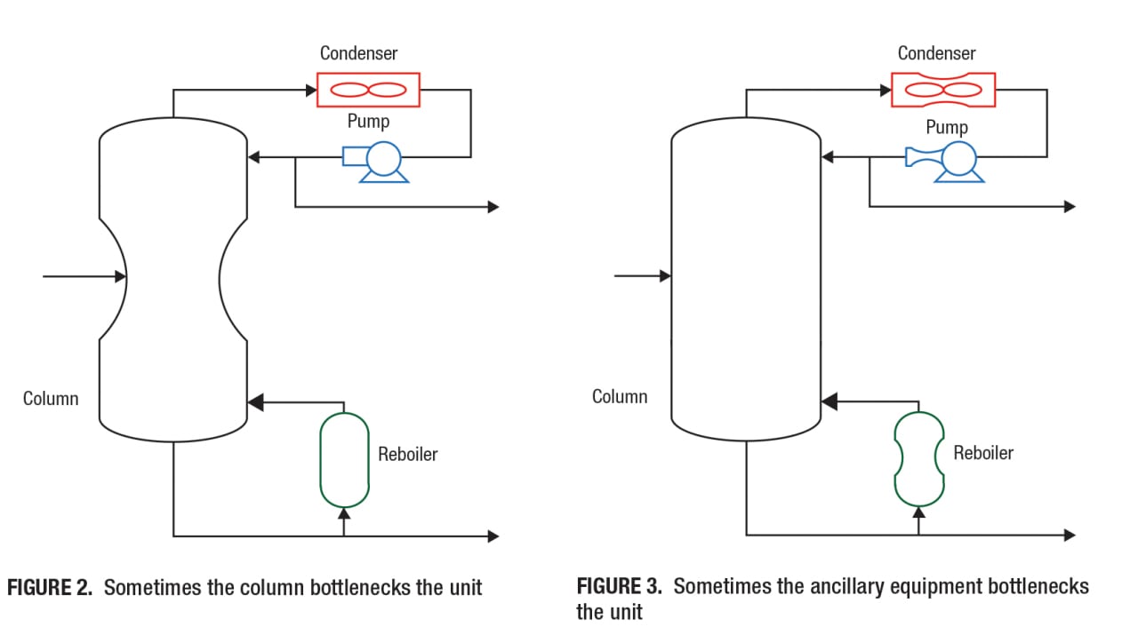
Computer simulations of columns will also help to identify bottlenecks in the columns’ ancillary equipment. Too often, columns are revamped with superior internals, and eventually, it may be determined that the old internals were not bottlenecking the unit; the problem might have been reboiler circuitry piping, an under-sized reflux pump, or condenser cooling water temperature, and so on [3]. Figure 2 illustrates a tower that is bottlenecked by its internals (trays or packings). Figure 3 demonstrates that the ancillary equipment often bottlenecks performance.
The target of some column revamps is an improved separation. Maybe a top product needs to be more pure. Maybe the losses of that product, out the bottom of the tower, need to be decreased. The pursuit of such targets absolutely requires the performance of process simulation work. Such work will sometimes include a multiplicity of feed cases, such as near-term, future, worst-case, best-case or other scenario. A serious revamp study usually begins with a simulation of the existing operation. In a perfect world, a perfect vapor-liquid equilibrium (VLE) thermodynamic model is employed in that simulation. A somewhat imperfect model can suffice as long as the number of equilibrium stages being exhibited by the existing, old trays or packings is reasonable. For example, a process simulation showing that 130 theoretical trays are being exhibited by 100 actual trays is not reasonable. The VLE model is probably wrong and a process simulation of the future conditions should not be trusted. For this particular example, a process simulation showing that 90 theoretical trays are being exhibited is reasonable. That VLE model is possibly “good enough.”
The target of some column revamps is energy reduction. Figure 4 applies to distillation columns. Two curves show the well-known distillation relationship between the number of equilibrium stages (NES) and the reflux ratio. The y -axis of this graph could be relabeled as number of theoretical trays (NTT). The present x-axis shows reflux ratio, but this axis could be changed to show energy consumption. Both of the curves of Figure 4 show that as the staging in a column is increased, the energy requirement decreases. There are minima, however, on staging and on reflux ratio. Figure 4 includes two curves, one for an easy separation and one for a difficult separation. As expected, the latter requires more stages, more energy or both.
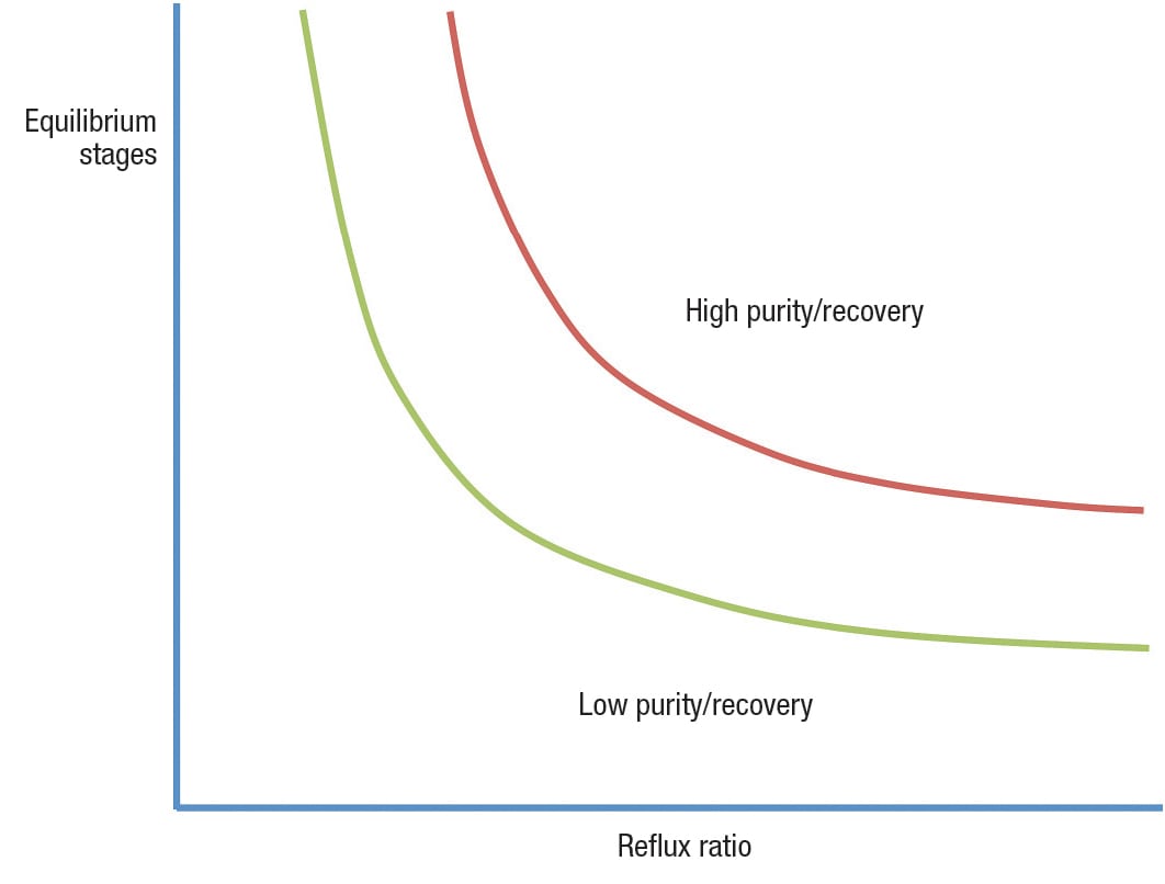
FIGURE 4. Attainment of purity and recovery target depend upon the number of equilibrium stages and the reflux ratio
Most importantly, Figure 4 shows that energy consumption can be reduced with more staging. More staging can be obtained with more trays, more-efficient trays, more packing or more-efficient packing. One way to place more trays or more packing in a column is to increase the height of the column. Indeed, sometimes, the head is cut off of an old column and a new spool piece is added to the shell to increase the column’s height.
Usually, however, increased staging is achieved as follows:
- Adding trays by decreasing tray spacings, for example, 100 trays at 24-in. spacings are replaced by 150 trays at 16-in. spacings
- Replacing random packing with more-efficient (that is, smaller) packing elements
- Replacing structured packing with more-efficient (that is, higher-surface area) structured packing
In all of these cases, the new trays or the new packings must be capable of handling the new internal flowrates, without flooding.
Figure 5 is a three-dimensional graph. The datum labeled “original column” shows the “as is” operating point. A feedrate increase could be achieved with a simple revamp, for example, higher capacity trays or higher capacity packings. Assuming that there were no changes in the tray or packing efficiencies after the simple revamp, the column would be operating at a higher reflux rate, but the same reflux ratio. With a simple revamp, the staging in the column is not changed.
![FIGURE 5. A simple revamp can yield a feedrate increase and there are times when a complex revamp can yield a larger feedrate increase [2]](https://www.chemengonline.com/wp-content/uploads/2015/04/45.jpg)
FIGURE 5. A simple revamp can yield a feedrate increase and there are times when a complex revamp can yield a larger feedrate increase [2]
Now imagine a complex revamp — for example, the replacement of 100 trays with 150 trays. Assuming a tray efficiency of 80%, the number of equilibrium stages supplied by the trays would be increased from 80 to 120. This has a large impact on the requisite reflux ratio, as shown in Figures 4 and 5. The reduced reflux ratio leads to a decrease in the reflux rate, a decrease in the reboiler boil-up and decreases in the internal vapor and liquid flowrates. The reduced internal flowrates make it possible to increase the feedrate to the column, as shown in the datum labeled “complex revamp.” Similarly, high-efficiency packings could replace less-efficient packings to achieve the benefits of a complex column revamp.
Mechanical considerations
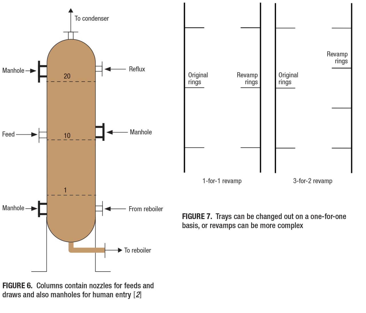
Figure 6 shows a very short distillation column with only 20 trays. Included is a feed nozzle half-way up the column. Process simulation work on any distillation column shows that there is an optimum feed point location, where energy consumption is minimized. That optimum location could be in the upper half or the lower half of the column. During some distillation column revamps, the feed location is changed. The obvious way to move a column’s feed point is to add a new nozzle to the column. This is not always easy. Another way to change a feed location is to use the old, original feed nozzle and then run a pipe up or down through a set of trays (or packings) and then terminate that pipe with horizontal distributor piping at the optimum feed location. Primarily, this internal piping strategy avoids welding a new nozzle to the outside of an old column.
An explosion that occurred in 1984 in Lemont, Ill., served as a wake-up call to global column-revamp practitioners. When welding work is performed on “old” pressure vessels, that work must be followed by local or total heat treating (stress relief). Such heat treating is expensive when performed correctly.
In columns, trays are supported by rings. With a new column, those rings are often welded to the inside of the column while the column is in the fabrication shop. Eventually, the column is shipped to the production site and the column is erected.
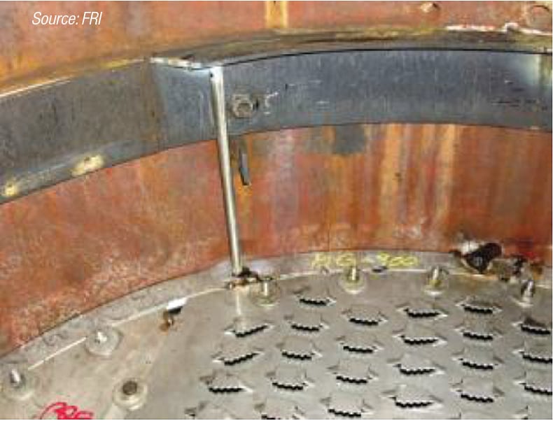
FIGURE 8. New tray rings can be welded to tower walls or they can be supported using posts that are attached to the old rings
Imagine a column with 100 rings and 100 trays. Imagine a scenario wherein the 100 trays are going to be replaced by 150 trays. This is sometimes called a “three-for-two revamp” and is shown in Figure 7. One option is to use many of the existing rings and then to weld many new rings to the inside of the column [4]. This welding will necessitate heat treating. Another option is to support new rings using old rings and vertical posts. As shown in Figure 8, FRI demonstrated the post-supporting strategy of new rings in one of its test towers. This strategy avoids the necessity for heat treating, because the new rings and posts are not welded directly to the shell of the pressure vessel.
Referring back to Figure 6, most columns contain manholes. These manholes allow humans to enter columns for inspection, maintenance and revamp work. Figure 9 is a photograph (side view) of one of FRI’s manholes. The inside dimensions (IDs) of column manholes are of extreme importance when planning a revamp and when designing parts for trays and for packing distributors. The parts must, of course, fit through the manhole, and then the parts must be “rotate-able” into vertical orientations, for transporting downward inside the column. Similarly, large blocks of structured packing must fit inside the open manholes. In some cases, large parts of trays and distributors are broken down, in the planning and drawing stages, into sub-parts. For example, a large central tray downcomer might be designed and fabricated as two pieces. In some cases, column-revamp work is facilitated by cutting the tops off of columns and then reattaching those tops after the revamp work is completed. Very unfortunately, the history of global column-revamp work includes numerous cases where tray and packing parts did not fit into columns after those parts were designed, fabricated and delivered to revamp sites.
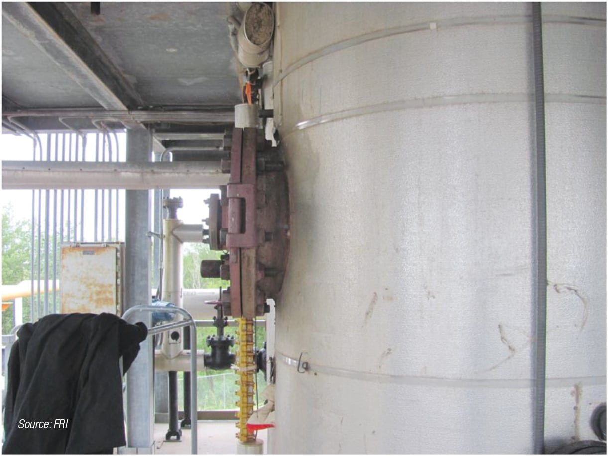
FIGURE 9. Column manholes allow humans and equipment to enter
Levelness
Some old and new columns are not perfectly straight, or upright. Long column shells are fabricated in pieces. Sometimes when the shell pieces are welded together, the column makes a slight turn. Additionally, long shells can become bowed, especially if left in a horizontal position in the sun for too long. Once a long column is erected, that is, uprighted, it is difficult to see if the column is bowed, especially because of the column’s insulation, ladders, platforms and piping hook-ups. On the other hand, if a column is not perfectly upright, that can often be seen from about 100 yards away. A column that is off vertical by only 1 deg can be seen by eye.
Columns that are not perfectly vertical usually have rings that are not perfectly horizontal. When trays or packing distributors are placed upon those rings, those trays and distributors are prone to malperformances — sometimes not meeting process targets. It is also, of course, possible that the rings were installed improperly in the shell fabrication shops. Tray and packing vendors, engineering companies and operating companies all have standards regarding ring levelness tolerances. Usually, larger tolerances are allowed at larger diameters. It is very important that tray and distributor installation companies adhere to these levelness tolerances, regardless of how difficult they sometimes appear to be. In worst-case scenarios, shims can be employed on the rings to install trays and distributors without significant out-of-levelness. Again, very unfortunately, the history of global column-revamp work contains numerous cases where non-horizontal trays and distributors performed poorly.
Gamma scanning
Before initiating serious column revamp work, a column should be gamma-scanned especially at processing conditions near its flood point. Gamma scanning can identify the location of any hydraulic bottlenecks in trayed or packed columns. Once the location has been identified, tray and packing engineers, especially from the vendor companies, can determine the reason that the hydraulic bottleneck is occurring. Column flooding is often defined as “liquid cannot get down the column.” When column flooding occurs, there are many possible reasons including excessive vapor traffic and excessive liquid traffic. Column flooding usually initiates at a single vertical point in a column. Because the full liquid stream is not getting past that point, the section of the column beneath the bottleneck is often starved of liquid. At the same time, the section of the column above the bottleneck is accumulating liquid. This starvation and accumulation are observable in thorough top-to-bottom gamma scans. Reboiler and condenser circuitry should also be scanned at those rates where a column appears to be flooded. Also, premature flooding is often attributable to solids and plugging. Sometimes, column internals can simply be cleaned, rather than replaced.
Larger columns
In 1985, the number of global columns over 300 ft in height could have been counted on one hand. Today, several global columns are approaching 350 ft in height.
In 1985, a propylene column 15 ft in diameter was considered to be “huge.” Today, propylene columns 30 ft in diameter have been commissioned and are being designed.
A column that is 30 ft in diameter has four times the cross-sectional area of a 15-ft-dia. column. As a result, with large-diameter trayed and packed towers, the possibilities for liquid and vapor maldistributions are greatly increased. With trays, for example, long liquid-flow path lengths help to create hydraulic gradients in the froths. In response to the froth height differences, vapor streams have a natural tendency to flow through the deck areas having the shortest froth heights. As a worst-case scenario, vapor crossflow channeling (VCC) can occur [5] and tray efficiencies can suffer.
Again, very large trays have very large deck areas. Such areas are particularly prone to froth stagnations, or even retrograde (backwards) froth flow. If properly designed and specified, push valves on those deck areas can keep the froths moving toward the outlet weirs.
Regarding packing, the difficulties associated with the attainment of perfect liquid distributions at the tops of packed beds are increased appreciably with very large column cross-sectional areas. Some companies, including vendors, insist that all liquid distributors be tested with water at vendor company test stands.
The bottom line is that, with trayed and packed towers, malperformances are more likely to occur before and after column revamp work, when tower diameters are extremely large.
Very large and very tall columns bring up other issues. Revamping such towers during 30-day turnarounds is often excessively challenging. A multiplicity of teams, and work elevations, are required. Each team requires an observer/coordinator at each manhole and also its own on-the-ground assistants to keep parts moving down and up the tower.
Tide marks
As trays and packings are being removed from a tower, those trays, packings and packing distributors need to be examined before they are discarded or reused. Besides plugging, one of the first things to look for is metal thinning due to corrosion. Some services are particularly prone to acid build-ups, and acids eat away at metals, including column shells. Sometimes, so-called “tide marks” can be seen on the inside walls of trayed columns that have been running for many years. Those tide marks show froth heights, and maybe froth height differences. Figure 10 is a photograph from one of FRI’s kettle reboilers [6]. Tide marks are clearly evident on the inside walls of that kettle. In this case, those tide marks indicate the average depth of the boiling pool.
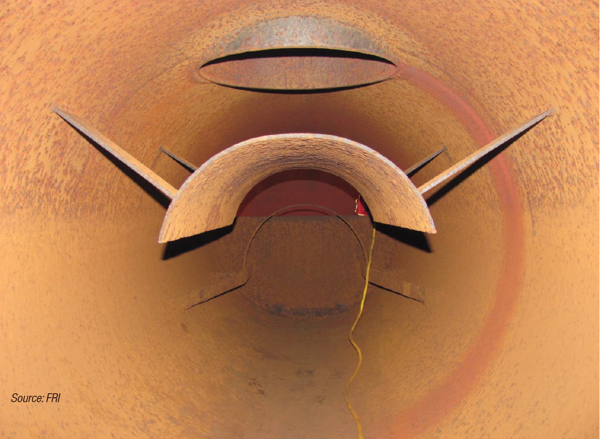
FIGURE 10. Tide marks can sometimes be found inside of old vessels, in this case, a kettle reboiler
Final post-revamp inspections
After any revamp, there comes a point in time when a column is ready for a final inspection, before the manhole covers are closed and the column is buttoned up. This inspection should always involve a member of the company that owns and operates the column.
Trays are usually equipped with manways that allow workers and inspectors to climb vertically through tray stacks. Multi-pass crossflow trays, such as four-pass and six-pass trays, are usually equipped with multiple vertical manway paths. The downcomers and anti-jump baffles of multi-pass trays make it impossible to inspect an entire freshly installed tray from just a single set of vertical manways. Such multi-pass trays require that each set of vertical manways be climbed through so that every area and volume of a freshly installed tray can be inspected before those manways and column manholes are closed.
It is, of course, impossible to climb vertically through a bed of packing, whether random or structured. Nevertheless, it often happens that liquid distributors are positioned at the same elevations as column manholes. It is therefore easily possible to inspect most packing distributors before the manholes are buttoned up.
All findings of column inspections need to be thoroughly documented, including inspector names and dates.
Safety considerations
General. There are many people who perform column revamps very regularly. There are other people who become involved in such work only occasionally, or even just once in a career. These people include engineers, technicians, mechanics, welders, electricians and so on. The next few paragraphs are particularly for the people who are not already experienced, and expert, at column revamp safety aspects.
Ultimately, you are responsible for your own safety. At the plant, you are in your shoes. Only you go where you go. You should not expect to have an experienced safety expert at your side everywhere that you go at a plant during a column revamp.
The first people to talk to regarding column revamp safety are the safety professionals and the experienced veterans (engineers and technicians) where you work. Your company has, or should have, procedures and policies regarding plant visits. Training classes will possibly be needed. Paperwork will need to be attended to, earnestly. A second group of people to talk to are the safety professionals and experienced veterans at the plant. This includes engineers, outside technicians and board operators. On an increasing basis, plants are providing safety training to first-time entrants to those plants. This training can last an hour or as long as three days. Sometimes, tests will need to be taken at the plant, to assure everybody that you are fully ready to encounter all of the known and potential hazards that are present near and in columns during revamps.
OSHA standards. There are several applicable federal Occupational Safety and Health Administration (OSHA; Washington, D.C.) standards. Certain states and localities have their own standards and these must, and should, be adhered to also. Among the applicable federal standards are the following:
OSHA Standard 29 CFR 1910.146 applies to entry into confined spaces. During a column revamp, some people need to enter the column. Those people need to know what was processed in the column. Were there any poisons or dangerous hydrocarbons or chemicals? Is the column properly blanked off so that those chemicals have no possibility to reenter the column? Has the appropriate equipment been locked out and tagged out (LOTO)? It should be assumed, by the way, that all valves leak. Has the column been steamed out? Aired out? Is the oxygen content going to be monitored continuously while the vessel is occupied?
Regarding entry to any confined space, a key player is the attendant, sometimes called the “hole watch,” who is usually positioned outside of any manhole where people enter the column. Nobody enters the column without the attendant’s full permission and knowledge. The attendant logs all entries and exits. The attendant has many other responsibilities, including the blowing of an air horn if any dangers arise outside of the column, and, the contacting of rescue personnel if anything goes wrong inside the column. The attendant must sometimes prevent the rescue team from rushing into the column if the rescue team might possibly suffer the same calamity as what brought the team to the column in the first place. Very unfortunately, a large fraction of confined-space rescues involve fatalities and the rescue teams end up focusing on body retrievals. Most importantly, the attendant should be regarded as “the boss.”
OSHA Standard 29 CFR 1910 also includes chapters regarding falls and fall-protection equipment. Falls are the most common cause of work-related injuries and deaths. Climbing up and down the outside of a column involves the risk of falling. Climbing up and down inside the column involves the same risk. As was stated previously, some of these newer columns are 350 ft tall. Body belts, harnesses, deceleration devices, lanyards, lifelines, arrest systems, ropes, ladders and scaffolds are all available to make the climbs safe.
OSHA Standard 1910.132 applies to personal protective equipment (PPE). For column revamp work, the following are regarded as possibly applicable PPE: hard hats, gloves, safety glasses with side shields, steel-toed boots, shields, barriers, respiratory devices and flame-resistant clothing. Anybody who wears PPE needs to be trained regarding the PPE. PPE should always be regarded as the last line of defense against injury. To avoid PPE coming into play at a revamp site, engineering controls, policies and procedures need to be in place, and adhered to. For example, platforms on the sides of columns have guardrails and toe guards. These are intended to prevent people or untethered equipment from falling off of the platforms. If equipment does somehow fall from a platform, hard hats being worn by the people underneath will lessen the injuries, if any, sustained by those people. The first line of defense is the guard rails and the toe guards.
Policies and procedures. LOTO stands for “lock out tag out” and is a policy and a procedure whereby energy sources (potential, kinetic, pneumatic, radiation, electric and so on) are totally isolated from humans. Dangerous machines are shut off and cannot be restarted easily. Hazardous power sources are isolated and made inoperative often via padlocks. Associated with those padlocks are cardboard or plastic tags that are easily seen and that identify the source of the padlocks. When two or more companies or subcontractors need to be protected from an accidental restart of those machines, it is sometimes required that those two or more companies each add their own padlocks to the machine.
JHA stands for “job hazard analysis” and can be applied to any small or large project. Via a JHA, the hazards associated with a project are identified. The means by which the dangers are eliminated, or reduced to reasonable levels, are listed and enacted. Most JHAs ultimately involve at least one multi-person meeting where the listed hazards and actions are discussed openly.
MOC stands for “memorandum of change.” Any change to a unit’s piping and instrumentation diagram (P&ID) or procedures needs to be preceded by an MOC, which should also involve an open discussion between many parties. MOCs, including the appropriate costs, ultimately need to be approved by management before a change or changes are actually effected. Once such changes have occurred, the unit’s process flow diagrams (PFDs) and P&IDs need to be updated to include the changes. All operating units must have up-to-date PFDs and P&IDs while those units are operating.
PSSR stand for “pre-startup safety review.” After a unit has been modified, and before the blinds are removed, the valves are opened and the pumps are restarted, a meeting should be held to determine whether the unit is truly totally ready to be placed back into service. Among the questions that need to be answered is this one: Have all affected employees been apprised or trained regarding the changes that have been made to the unit?
Miscellaneous. Column owners or operators rarely do their own revamp work. Some vendors of tower internals have field service organizations at their disposal. Otherwise, there are very experienced companies that perform such work.
Before any column can be entered by humans it must be steamed-out, especially to remove chemicals that adhere to the column wall and the column internals — subsequent to the pump-out. Every column and service is different. Some columns are steamed for 24 h, whereas others require three full days. Thereafter, air movers are required to establish breathable atmospheres and to prevent air from becoming dangerously stale. Thereafter, the column is still not ready for full entry. Workers with respiratory equipment should peer carefully into the column and take samples of any liquids or solids (for instance, deposits) that are found. Those samples require analyses. For example, pyrophoric compounds, such as polybutadiene, are sometimes in evidence in olefin plant depropanizers, even after long steam-outs. It sometimes takes a full week, after shutdown, for some columns to be totally ready for human entries.
Column revamp work, especially for those people who do not get involved in it routinely, is very tiring. For example, when climbing up the outside of a column, a worker’s arms become fatigued before the legs. On very rare occasions, with very tall columns, special scaffolds are erected and those special scaffolds are equipped with elevators. Revamp workers who have such elevators at their disposal should consider themselves lucky.
When first entering any plant, notice should be taken of the wind sock and the wind direction. If anything goes wrong in a nearby operating unit, know where to go to avoid any harmful vapors, including smoke.
Column revamps can occur anywhere and during any season. Dress appropriately. Wind speeds near the tops of columns can easily be twice those at ground level. Wherever you go when you are at a plant, somebody must know where you are.
Whenever two or more teams are working at different elevations inside a column, means must be in place to assure that workers lower in the column are not struck by objects that fall by accident from above. The fact that all of the people inside the column are wearing hard hats is insufficient. Nets can be strung horizontally inside columns to protect the lower workers.
New plants have manholes that are nominally 24 in. in diameter. Older plants often have manholes that have IDs of only 17 in. Some humans simply will not fit through such small manholes, especially when they are wearing full safety gear. Then, even if those people fit through those manholes, rescue difficulties are exacerbated.
People who enter columns, and especially tall columns, for the first time sometimes become petrified — and even dysfunctional. Attendants must keep an eye out for such people and such people should not be allowed to enter columns until they can demonstrate that their fears are under control.
Structured packing has been known to catch fire in dozens of columns [7]. Usually, sparks and slag from welding ignite deposits on the structured packing sheets and then the burning spreads to the sheet metal. Once these fires begin, they are very difficult to stop. Some revamp companies and some operating companies insist that structured packings be removed from a column before any welding work is performed above those packings.
General. Very unfortunately, some injuries are permanent. Like they said at IBM — think! Like one of DuPont’s safety programs — Take Two minutes before embarking on even the smallest of new adventures. Seek the advice and assistance of safety professionals and experienced veterans, including board operators and outside technicians. Some of those people have made safety-related mistakes and are eager to tell you about those mistakes. While at the plant, never be lulled into a false sense of security. Expect the unexpected — and “unexpect” the expected.
It has been estimated that there are 100,000 columns in the world. Many of them have already been revamped. All of them are targets for potential future revamps. If you become involved in one, or some, of those revamps, be totally prepared. Be safe. ■
Edited by Gerald Ondrey
Acknowledgements
The authors express their gratitude to the many staff members of Gallop Field Services and Fractionation Research Inc. who contributed to the material of this article.
References
1. Resetarits, M.R. and Lockett, M.J., Distillation, “Encyclopedia of Physical Science and Technology,” 3rd Ed., Vol. 4, Academic Press Inc., 2002, pp. 547–559.
2. Gorak, A. and Olujic, Z., “Distillation: Equipment and Processes,” 1st. Ed.. Elsevier Publishing, Chapter 2 — Distillation Trays; Chapter 3 — Random Packings; and Chapter 4 — Structured Packings, 2014.
3. Kister, H.Z., “Distillation Troubleshooting,” AIChE: Wiley-Interscience, Hoboken, N.J., 2006.
4. Resetarits, M.R., Agnello, J., Lockett, M.J. and Kirkpatrick, H.L., “Retraying increases C3 splitter column capacity,” Oil and Gas Journal, June 6, 1988, pp. 54–59.
5. Kister, H., Can valve trays experience vapor cross-flow channeling?, The Chem. Engineer, June 10, 1993, p. 18.
6. Resetarits, M.R., Cai, T.J., Chambers, S., Pless, L. and Carlson, R., Gamma Scanning of a Kettle Vapor Line, AIChE Fall Meeting, Oct. 30, 2012.
7. FRI Design Practices Committee, Causes and Prevention of Packing Fires, Chem. Eng., July 2007, pp. 33–42.
Authors
 Mike Resetarits consults in the areas of distillation, absorption and extraction, having worked in those areas for 40 years (Email: mike.resetarits@att.net). He has appreciable Expert Witness experience. He began his career in separations with Union Carbide Corp. He then worked for UOP and then Koch-Glitsch and then as an independent consultant. From 2008 until 2014, Resetarits served as technical director at Fractionation Research Inc. (FRI) in Stillwater, Okla. He holds a B.S.Ch.E from SUNY at Buffalo and an M.S.Ch.E. from Northwestern University. He also holds an M.B.A. from Canisius College.
 Tim ReBeau is vice president and co-owner of Gallop Tower Field Service (TFS; 1602 Mooney Rd. Houston, TX 77093; Phone: 281-449-1051; Fax: 281-449-4241 Email: tim.rebeau@ gallopcgi.com). He currently oversees the estimating and sales departments for tray and packing installations, welding and revamp projects for distillation columns. He has 20 years of experience, beginning his career at Cana-Tex (1995–2005) and, after purchase by Sulzer Chemtech (2005–2010), continued there until 2010. In 2010, ReBeau and business partner Mike Mitchell started the TFS division of Gallop, which is dedicated to tower internals installations and revamps.
 Terry Thurber is currently the Safety Focal Point at Fractionation Research, Inc. (FRI; 424 S. Squires St., Suite 200, Stillwater, OK 74074; Phone: 405-385-0354; Fax: 405-385-0357; Email: safety@fri.org). He has worked in both the pipeline transportation and storage, and process system sides, of the energy industry. He has been involved in well over one hundred permit-required confined space entries as either an attendant, entrant, entry supervisor, program auditor, or trainer. He is certified through OSHA Training Institute to conduct training of OSHA 10 and OSHA 30 classes and he is also a certified safety and health official.