The ability to reduce fugitive emissions through the use of strategic design modifications not only protects workers and the environment, but reduces losses of valuable process materials
The industrialized nations of the world have all placed increased emphasis on the control of industrial emissions, to protect the atmosphere. Many types of emissions result from process streams, and as such, can be controlled by operators with the right engineering interventions. However, a considerable proportion of emissions are unanticipated fugitive emissions [ 1]. Fugitive emissions are defined as a chemical, or a mixture of chemicals, in any physical form, released as a result of an unanticipated or spurious leak in an industrial site [ 2,3,4]. Such leaks occur because of discontinuities in the solid barrier that is intended to maintain containment.
Worldwide, fugitive emissions from industrial applications amount to more than a million metric tons per year (m.t./yr), and fugitive emissions in the U.S. are estimated to be in excess of 300,000 m.t./yr, accounting for about one third of the total organic emissions from chemical plants [ 5]. This situation is mirrored in Europe, and is likely worse in other parts of the world, where emission standards and policing levels may be lower.
Fugitive emissions create not only environmental and health issues, but they have economic impacts, as well. Fugitive emissions represent a loss of potentially valuable materials and reduce overall plant efficiency [ 6]. In many cases, the true economic impacts are not recognized, because many of the costs associated with fugitive emissions are not readily apparent. Since October 2007, all existing processing plants and power stations within the European Union (E.U.) have had to comply with the IPPC directive 96/61/EU, which aims to improve the management of industrial processes and ensure a higher level of protection for the environment. The challenging environmental, health and economic demands that are driving the need to reduce leaks and fugitive emissions [ 7] are more urgent than ever. The implementation of legislation in the U.S. governing emissions of volatile organic compounds, together with E.U. directives, has provided a stimulus for work aimed at reducing fugitive emissions.
Conceptual design and FEED
This article focuses on how fugitive emissions should be considered during the conceptual design and front-end engineering design (FEED) stages. As shown in the example in this article, an emission factor is applied to estimate the amount of potential fugitive emissions that could be expected, as well as the potential atmospheric concentration and associated health risks. The health risk is then calculated using the established Health Quotient (HQ) Index, a dimensionless value that indicates a relative health risk between two or more processes or scenarios based on the amount of fugitive emissions generated by both (HQ is typically expressed as a ratio of emission concentration and exposure limit).
The example discussed in this article demonstrates the estimation of potential fugitive emissions from an extractive distillation system that consists of two distillation units. The process involves the extraction of isopropanol (IPA) from water using ethylene glycol as the entrainer (the entrainer is the solvent used in an extractive distillation system). Since actual plant monitoring data were not available, an estimation method was used, based on the Average Emission Factor approach discussed in Ref. 8.
The fugitive emissions rate obtained using that methodoogy was then used as the input data to determine the resulting chemical concentration (based on the volumetric flowrate of air) within the process area. In this estimation exercise, the volumetric flowrate is estimated, since the process is still in the design phase. This calculation requires data on wind speeds, plot dimensions and the maximum height of the column or vessel below which the leak sources reside [ 9–11]. The details on how the calculations are performed are described below.
The example discussed here examines the estimation of a chemical concentration that could result from fugitive emissions for both the process flow diagram (PFD) and the piping and instrumentation diagrams (P&ID), both of which are important diagrams used during the conceptual design and FEED stages, respectively. Note that one may further differentiate the calculation using preliminary PFD and detailed PFD, with the latter having results of mass and energy balances [ 9]. Only the latter one (that is, with detailed mass and energy balances available) is considered in this article.
The estimated values calculated using the methodology described here serve as input data for estimating the associated health risk for the proposed design at any stage. Such risk estimation is vital in predicting the potential adverse health impacts workers could encounter, due to potential fugitive emissions released from the proposed process or plant design.
Illustrative example
The PFD of extractive distillation for the separation of IPA and waterconsists of two distillation columns with a direct sequence (Figure 1). In the extractive column (EXT), ethylene glycol (EG), which is used as the entrainer (Stream S), is introduced at the stage above the azeotropic feed. This design allows for enhanced contact with the binary mixture, which facilitates separation. Stream F consists of a fresh feed of the binary mixture (65% IPA and 35% water).
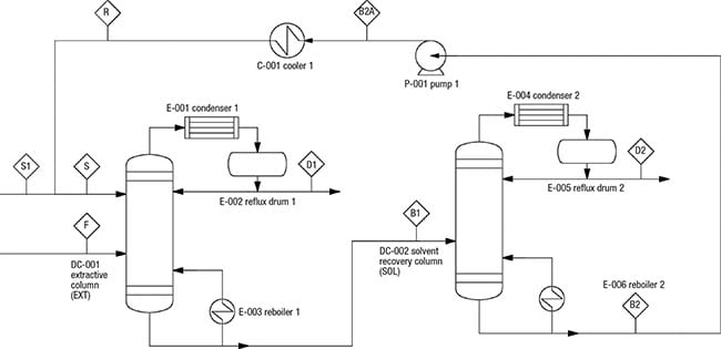
Figure 1. This diagram shows the PFD of an extractive distillation system for IPA-water separation. This system provides the basis for the estimation methodology discussed in this article
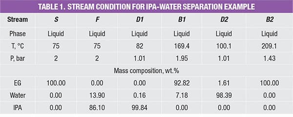
The entrainer EG changes the relative volatility of the chemicals and directs IPA to the distillate stream of the EXT column. At the same time, water and EG leave in the column bottom stream, and are fed to the solvent-recovery column (SOL). In the latter, the heavy entrainer EG will be separated from water by a binary distillation and the EG is recycled to the EXT column. The stream conditions (temperature, pressure and mass compositions) are shown in Table 1.
Calculation for the PFD level
The potential fugitive emissions (FE) rate for the PFD level is calculated based on the pre-calculated module data, as shown in Table 2. These data were originally reported by Hassim and others [ 9] to assist designers in performing emissions estimation from their process. Despite this apparent simplification, these data are reliable since the emissions values in the database were calculated based on the actual P&ID of the typical process modules (unit operations) in chemical plants. Note that there are useful data for other reported unit operations, such as columns, reactors and more. Readers may refer to the original source [ 9] for these data.
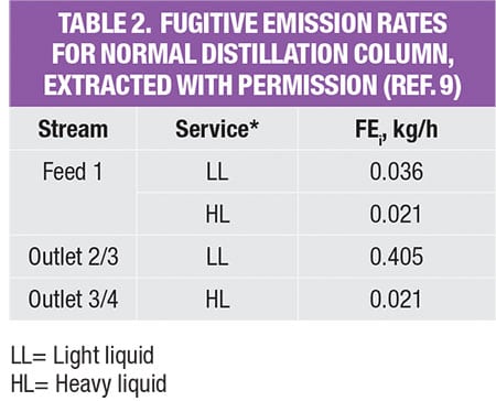
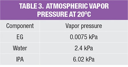
As shown in Table 2, in order to estimate fugitive emissions, the service type of the streams must be identified. For liquid streams, the stream service type is classified according to their vapor pressure and mass compositions. To be classified as light liquid (LL), the vapor pressure of the pure component at 20°C needs to be higher than 0.3 kPa (vapor pressure for the three pure components, in the example is given in Table 3). For a liquid stream with mixture of chemicals (which is very common in the chemical process industries), the summation of these components should be ≥20 wt.% in the stream mass composition. Otherwise, the liquid stream is regarded as heavy liquid (HL). As for gas streams, the classification is much more straightforward, as it is regarded directly as gas service.
The values in the database yield the amount of potential fugitive emissions from that particular process stream. Because the process stream is comprised of a mixture of chemicals, the stream emissions rate is multiplied by mass composition of each chemical component, to obtain the amount of potential fugitive emissions of the individual components, respectively; results of this calculation for the case example discussed here are shown in Table 4.
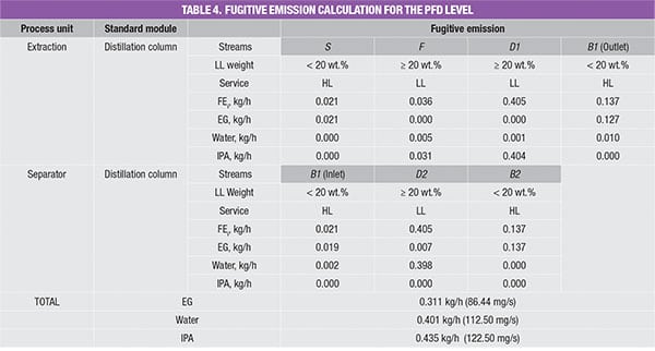
For example, the feed stream of the extractive column (Stream F) consists of 13.9% of water and 86.1% of IPA. Since its LL weight is higher than 20 wt.%, the estimated fugitive emission of the stream is reported as 0.036 kg/h, according to Table 2. This estimated stream value is assumed to be contributed by water and IPA according to their mass composition, that is, 0.005 kg/h (=0.036 × 13.9%) and 0.031 kg/h (=0.036 × 86.1%), respectively. The total amount of fugitive emission for the respective component is then determined by summing up the emisEGsion rates of this particular chemical component in all process streams throughout the process, given in the last three rows in Table 4.
Calculation for the P&ID level
The P&ID is an important diagram used during the FEED stage of plant design. By taking the P&ID into consideration, we can estimate fugitive emissions in a more accurate and wide-ranging manner because the diagram provides more details about the process. At this stage, the actual piping and connections are made available, therefore enabling more precise data estimation.
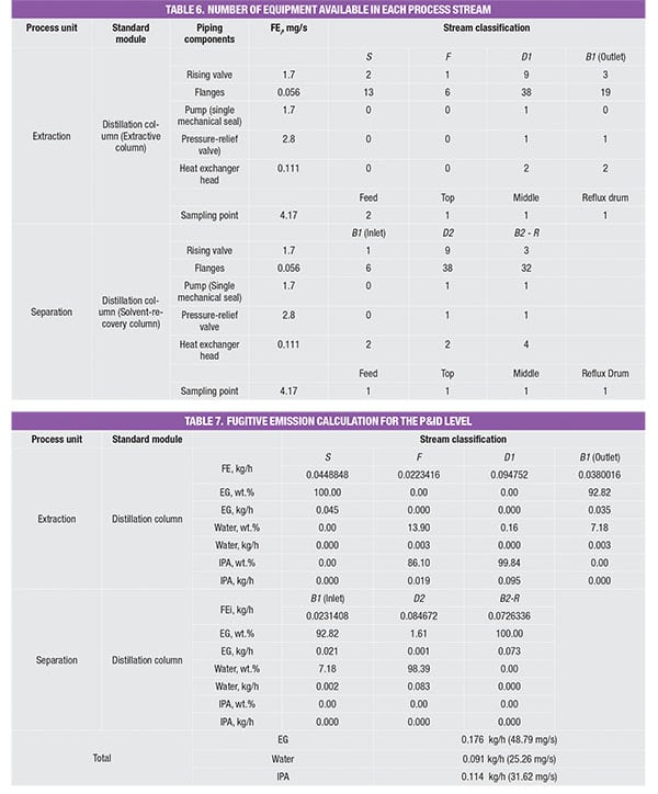
As shown in the P&ID diagram for the IPA/water separation in Figure 2, identification of all potential leak sources (flanges, relief valves, valves, pumps, sampling points, and heat exchanger heads) are calculated using the guidelines provided in Table 5.
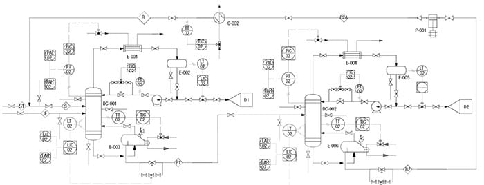
Figure 2. Here is the P&ID for the extractive distillation system used for IPA-water separation, which is discussed in the case example profiled here
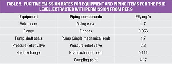
As shown in the database (Table 5), the emissions rate is now more equipment-specific. At this stage, all piping and instrumentation have been identified and more accurate emission factors are used to estimate the fugitive emission caused by the extractive distillation system. Note that data for other equipment, such as compressors, rotary, bolted manways and hatches were also reported by Hassim and others in Ref. 7.
The number of piping equipment components is first identified and summed to obtain an appropriate emission factor, as shown in Table 6. Similarly, the emissions rate for each process stream is determined based on the respective component mass composition, as shown in Table 7. Similar to the PFD case, the total emission rate for the respective components is estimated by summing the respective emission rates in the individual streams.
Estimation of health risk
The section above allows us to determine the fugitive emission rate at different stages of design. However, the HQ is determined based on chemical concentration. Therefore, estimation of volumetric flowrate based on wind speed and process module area is required to obtain the emitted chemical concentration. The relationship between emission rate and concentration is given by Equation (1):
![]() (1)
(1)
Where:
C i = The concentration of chemical i, mg/m 3
FE i =The emission rate of chemical i, mg/s
V∙ = The air volumetric flowrate, m 3 /s, which is calculated based on Equation (2):
![]() (2)
(2)
Where:
v = wind speed, m/s
A n = process module area, m 2
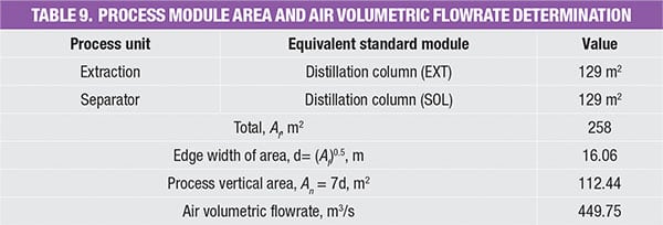
As indicated by Equation (2), the area of the process modules is needed in order to determine the air volumetric flowrate. Note that there are differences when estimations are done based on the PFD and the P&ID. The latter takes wind direction into account, as the real plot plan is available, resulting in a more accurate estimation of the cross-sectional area.
On the other hand, values derived at the PFD level are based on the average floor area, average wind speed and average height of piping components. For the simple example that involved only two distillation columns, estimation of airflow based on the PFD is adequate.
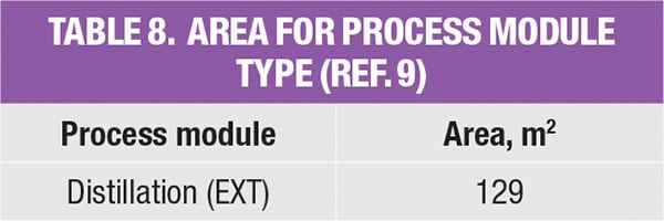
Table 8 shows a reported average floor area for some common modules in the chemical process plants [ 9]. Readers may also refer to the original source for data of other process module, such as flash column, stripper, compressor and so on. The average floor area for the IPA/water separation example is hence calculated based on the reported value for the distillation module (that is, 129 m 2, as shown in Table 9). The main assumption made is that the plot plan is a square shape (to obtain the edge width area), while the process vertical area is calculated using an average piping height of 7 m.
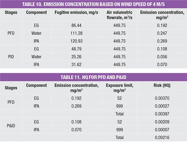
As the emission rate for respective chemicals in the process stream has been identified in the PFD and P&ID stage, the concentration for each stage can be determined, based on the calculated volumetric flowrate of air. This is shown in Table 10.
As the components involved are classified as non-carcinogens, the method used to estimate the risk of chronic exposure is to calculate the HQ, using an exposure limit based on 8 h. As noted, HQ is typically expressed as a ratio of emission concentration and exposure limit. As the system consists of a mixture of components, the HQ mix is the summation of the HQ values of the individual components. An HQ value of <1 is widely acceptable, where the associated risk is considered minimal. Results (Table 11) show that the extractive distillation system yields HQ values of 0.00397 and 0.00216, for the PFD & P&ID level, respectively. Both values fall well below the acceptable safe range of <1.0, indicating that the system is relatively safe.
Reduction of fugitive emissions
Although it has been identified that this extractive distillation system is relatively safe, additional efforts are still needed to continuously improve the health quality of the process plants. According to material safety and data sheet (MSDS), longterm exposure to IPA and EG can cause targeted organ failure. Process operators should seek methods to further reduce fugitive emissions due to the process operations.
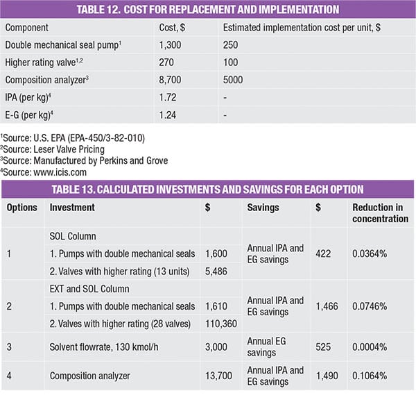
A few improvement strategies are shown in Table 13. For instance:
- Option 1 involves modification of valves (to use those with a higher rating) and also pumps (to favor those with double mechanical seals) in the solvent-recovery column (SOL)
- Option 2 includes replacement of valves (to use those with higher rating) and also pumps (to favor those with double mechanical seals) in both the extractive and recovery column
- Option 3 involves reducing solvent (EG) usage
- Option 4 introduces an online sampling method to reduce the number of sampling points (which is the source of fugitive leakage)
These options were evaluated monetarily, in terms of investment made and savings obtained, as compared to the base case. The investment made takes into account of modification and implementation costs (Table 12). For instance, installing 13 units of valves with a higher rating would cost a total of $4,810 [(270+100) × 13)]. On the other hand, the savings obtained refers to the amount of emissions prevented annually, reflected as loss of product and thus calculated as a function of the prevailing chemical price (Table 12). Table 13 shows the investments and saving for all options, which are also plotted on the impact diagram in Figure 3.
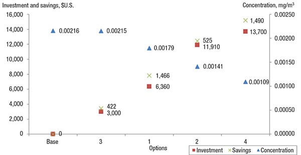
Figure 3. This impact diagram shows the savings, investment and reduction in emissions concentrations for the various options (listed in Table 13), allowing engineers to assess their options
As shown in Figure 3, as the concentration of fugitive emissions decreases, the savings and investment made increases, as a function of the higher cost of piping and equipment that uses better sealing and sampling. The use of modern piping equipment will further reduce fugitive emissions, thus allowing more chemicals to be retained within the system. These are a few proposed modifications that could be looked into to reduce fugitive emissions. However, the best option will be determined on a case-by-case basis.
Final thoughts
A health-risk assessment based on fugitive emissions was carried out to estimate the potential hazard level of the system discussed here. The results used two different methods of estimation at different levels of the design phase. As seen from the comparison, the fugitive emission value is the lowest in the P&ID stage, as the estimation uses more accurate emission factor data. In addition, at this stage, the number and type of the piping components and fittings employed in the process are known more accurately. Processes with a HQ value <1.0 are considered to fall safely within the acceptable range.
Nevertheless, modifications can still be done to improve the system. Certainly, for cases where the calculated risk is beyond the acceptable range, optimization needs to be carried out to reduce the risk. Optimization may involve reduction of solvent fed, piping modifications and more, to reduce the fugitive emissions to safer level. This effort improves operation in process plants (by reducing potential losses of valuable materials) and helps to protect workers and the environment.
Edited by Suzanne Shelley
References
1. Onat, A., A review of fugitive emissions, Sealing Technology, October, 2006.
2. Ellis, B.S., Emissions legislation — Development and progress, In International Seal Forum at Achema 97 Frankfurt, 1997.
3. ESA/FSA (European Sealing Association/Fluid Sealing Association), Guidelines for Safe Seal Usage — Flanges and Gaskets. Publication number 009/98, 1998.
4. ESA (European Sealing Association), Sealing Technology — BAT Guidance Notes, Publication number 014/05, 2005.
5. Lakhapate, P.J., Fugitive emissions — The bad guys of the pollution world who avoid even the toughest seals. Science in Africa, www.scienceinafrica.co.za/2006/april/fugitiveemissions.htm, April 2006.
6. Szweda, R., Fugitive emissions: The matter of imperfect seals. Sealing Technology, November 2000.
7. Nicholls, T., Maintaining integrity — A managed approach.Valve World, September 2005, www.valve-world.net.
8. EPA, Protocols for generating unit-specific emission estimates for equipment leaks of VOC and VHAP, Publication number EPA-450/3-88-070, North Carolina, 1988.
9. Hassim, Mimi H., Alberto L. Pérez, and M Hurme. Estimation of chemical concentration due to fugitive emissions during chemical process design, Process Safety and Environmental Protection, 88.3, 2010, 173–184.
10. Hassim, M.H., and M. Hurme. Inherent occupational health assessment during basic engineering stage, Journal of Loss Prevention in the Process Industries, 23.2, 2010, 260–268.
11. Hassim, M.H., and M. Hurme. Occupational chemical exposure and risk estimation In process development and design, Process Safety and Environmental Protection, 88.4, 2010, 225–235.
Authors
 Yieng Shing Seah recently completed her chemical engineering undergraduate program at the University of Nottingham, Malaysia Campus (Dept. of Chemical and Environmental Engineering; Phone: +6011-23240305; E-mail: [email protected]). Her research interests are in the area of process safety and food processing. Her undergraduate research project on lipase purification has resulted in another recent publication in ISI journal Separation and Purification Technology.
 Dominic C. Y. Foo, Ph.D, P.E. is a professor of process design and integration at the University of Nottingham, Malaysia Campus (Dept. of Chemical and Environmental Engineering, and Center of Excellence for Green Technologies, University of Nottingham Malaysia Campus, Broga Road, 43500 Semenyih, Selangor, Malaysia; Phone: +60(3)-8924-8130; Fax: +60(3)-8924-8017; E-mail: [email protected]). He is a professional engineer registered with the Board of Engineers Malaysia. Foo is also the winner of the Innovator of the Year Award 2009 from IChemE U.K., Young Engineer Award 2010 from the Institution of EngineersMalaysia, Outstanding Young Malaysian Award 2012, Outstanding Asian Researcher and Engineer of the Society of Chemical Engineers, Japan (SCEJ), and Top Research Scientist Malaysia 2016 from the Academy of Science Malaysia. He has more than110 published papers in a variety of chemical, energy and environmental engineering journals. Foo is also the Editor-in-Chief for Process Integration and Optimization for Sustainability, the subject editor for Trans.IChemE Part B — Process Safety and Env. Protection, and an editorial board member for Chem. Eng. Trans., Water Conservation Science and Engineering. He is also the author of the textbook of “Process Integration for Resource Conservation,” published by CRC Press in 2012. He obtained his B.Eng., M.Eng. and Ph.D., all in chemical engineering, from Universiti Teknologi Malaysia.
 Mimi Hassim, Ph.D., C.Eng., is a senior lecturer of chemical engineering at Universiti Teknologi Malaysia (Dept. of Chemical Engineering, Universiti Teknologi Malaysia, UTM Skudai, 81310 Johor, Malaysia; Phone: +60(7)-553-5548; Fax: +607-558-1463; E-mail: [email protected]). She is a chartered engineer with the Engineering Council U.K.. She received her B.Eng. degree from Universiti Teknologi Malaysia, M.Sc. degree from Loughborough University (U.K.), and doctoral degree from Aalto University School of Science and Technology (Finland). Hassim is an established researcher working on inherent occupational health studies of chemical processes. She has published more than 50 journal and indexed papers, and has presented in various conferences. Hassim has been chosen to represent the Malaysian Industrial Hygiene Association (MIHA) to present her work in the 31st Annual Conference & Exhibition organized by The Australian Institute of Occupational Hygienists; and full sponsorship by the ASEAN University Network/Southeast Asia Engineering Education Development Network (AUN/SEED-Net) to represent UTM in the Regional Conference on Natural Disaster (RCND) in Jogjakarta. She was invited to be the keynote speaker in the Symposium on Process Safety at Safety Centre, IIT Gandhinagar. Hassim also serves on the international scientific committees for several international conferences. She is also the subject editor (Chemical Safety and Occupational Health) for the Process Safety and Environmental Protection, a guest editor for Jurnal Teknologi, and the technical English editor for The Journal of Sustainable Development of Energy, Water and Environment Systems (JSDEWES). Hassim is a member of the Global Young Academy and currently serves as the General Secretary of the Malaysian Young Scientist Network.