Ceramic filters are well suited for high-temperature processes that are subject to strict emissions limits, including those for dioxins
About IncinerationIncineration processes are being widely used more and more to deal with the disposal of waste materials. In many countries, land filling of waste materials is not practical or desirable due to a lack of appropriate sites. Incineration has the benefit of reducing both the volume and mass of waste, thus reducing the amount of material to be disposed of. Incineration is now applied to a wide range of waste streams from high-tonnage municipal solid waste (MSW) through to the lower-tonnage specialty wastes produced by industrial processes. However, whatever the application, the imperative for the incineration process is broadly the same — a reduction in mass and volume while rendering the remaining waste material as inert as possible and, of course, producing the absolute minimum of emissions. Waste incineration, as with other industrial processes, has been the subject of ever tightening emissions legislation in recent years. Public disquiet over incineration processes and the generation of potentially dangerous emissions has subsequently, detrimentally affected the approval of many new installations. Consequently, the industry has sought effective post-incinerator processes for dealing with off gases in terms of reducing and eliminating emissions and where practical, recovering useful energy. Many techniques and combinations of techniques have been developed and are under development — a broad overview of which is beyond the scope of this paper. |
Ceramic filters offer practical operating benefits and commercial competitiveness in pollution abatement applications where processes combine elevated-temperature off gases with the need for high levels of corrosion resistance and the ability to eliminate dust emissions. This article discusses the applicability of ceramic filtration technology, with focus on, and examples of its use in incineration processes.
The ability to deliver low emissions, even with fine particles that are 2.5 micrometers (µm) or smaller (PM 2.5), while operating at an elevated temperature is the primary driver for the application of ceramic elements to high temperature processes that are subject to strict emissions limits. Such processes include metal smelting, chemicals production and waste incineration. In the latter case, ceramic elements have been applied to a number of small- to medium-scale incineration duties including medical waste, soil cleaning, asphalt recycling, industrial waste, chemical waste and building waste.
Several new, high-temperature incineration installations have been set up to deal with waste that is of mixed composition from various sources. Ceramic elements have been selected as the filter medium for a number of these installations. Of particular interest are the emissions of dioxin chemicals and particulate matter that have been under close scrutiny since the 1990s. Official emissions reports commissioned for these plants indicate emissions well within regulated limits.
Ceramic filtration technology
The concept of using a refractory ceramic material to form a filter medium, predominantly for use at elevated temperature (generally in the region of 200 – 400°C, but can be up to 900°C) has been around for many years [ 1]. One of the earlier forms of ceramic filter was devised for advanced power-generation applications with the requirement for operation at high temperature and high pressure. In the form of flanged tubes, closed at one end, these “high density” media are still in widespread use across a broad range of applications.
Low-density ceramic filter elements (hereafter referred to as ceramic elements) were initially developed in the middle 1980s. One of the first applications for ceramic elements was in thermal soil remediation. This process involves driving off the volatiles from contaminated soil in a rotary furnace to decontaminate it and make it reusable. The first stage in the complex off-gas treatment train is high temperature filtration, which removes particulates from the gas prior to further processing.
The ceramic elements manufactured in the middle 1980s were sectional, meaning they were built up from a series of inner- and outer-tube sections. The first monolithic elements were produced around the late 1980s and early 1990s. One of the early applications envisaged was advanced power generation, so the form of the first monolithic ceramic element was typical of the high-density elements being applied in the development of advanced power-generation technology — it was a 1-m-long tube, with a 60-mm outside dia., closed at one end and with an integral mounting flange at the other end.
Table 1 summarizes the main characteristics of the two types of elements referred to as low and high density. In addition to the characteristics outlined in the table, one major difference between high- and low-density ceramic filter elements is the forming method. Typically, high density elements are manufactured from refractory grains (such as alumina or silicon carbide) by pressing or tamping to form the basic shape. Low-density ceramic filter elements are vacuum formed from a slurry of refractory fibers to produce a blank, which is machined to shape, or in some cases to produce the final shape. It is also worth mentioning that ceramic filter elements are also produced in the form of plain tubes and can be applied to “inside out” filtration as well as “outside in”. Normally, however, “outside in” filtration is employed.
| High density | Low density | |
|---|---|---|
| Structure | Granular | Fibrous |
| Density | High | Low |
| Filter drag | High | Low |
| Porosity, % (inverse of resistance to flow) | 0.3 – 0.4 | 0.8 – 0.9 |
| Tensile strength | High | Low |
| Fracture mechanism | Brittle | Ductile |
| Thermal shock resistance | Low | High |
| Cost | High | Low |
Characteristics and benefits. The key characteristics of ceramic elements are summarized in Table 2. Ceramic elements are formed from refractory ceramic fibers with a fiber diameter of around 3 µm. Fiber diameter is crucial to promoting surface filtration and thereby good filtration characteristics. The structure and composition of ceramic elements confer three principal benefits for the technology:
-
High-temperature filtration capability
-
High collection efficiency
-
Corrosion resistance
Although the maximum use temperature claimed by the various manufacturers for their ceramic elements varies, it is typically stated as 900°C (1,650°F). This temperature is well above that required by the majority of “end-of-pipe” air pollution control (APC) duties that utilize traditional fabric bags for particulate capture. The ceiling temperature for commonly used fabric-bag materials is shown in Table 3.
| Form | Monolithic rigid tube |
| Composition | Refractory fibers plus organic and inorganic binding agents |
| Porosity | about 80 – 90% |
| Density | about 0.3 – 0.4 g/cc |
| Support | Self supporting from integral flange |
| Geometry | Outer dia. up to 150 mm; Length up to 3 m |
| Operating Temperature (°C) | ||
|---|---|---|
| Continuous | Surge | |
| Sulfar (“Ryton”) | 180 | 200 |
| Aramid (“Nomex”) | 200 | 240 |
| Polyimide (“P84”) | 240 | 260 |
| PTFE (“Teflon”) | 260 | 280 |
| Glass | 260 | 300 |
| Ceramic elements | 900 | 900 |
The elevated ceiling temperature of ceramic elements coupled with high filtration efficiency constitutes the basis for selection of the technology. Where the off gas to be filtered is consistently at a temperature below 250°C, then a needlefelt or coated needlefelt manufactured from a traditional polymeric material will often be adequate. However, stringent emissions regulations coupled with an elevated or variable off-gas temperature can be too tough for polymeric fabrics and favor the application of ceramic elements. Examples of the emissions achieved by ceramic elements are presented in Table 4.
| Process | Dust loading | Particle size | Emission level | Inferred efficiency |
|---|---|---|---|---|
| mg/Nm 3 | d 501,µm | mg/Nm 3 | % | |
| 1. Diameter of median size particle | ||||
| Zirconia production | Up to 8,000 | 1.2 | 0.8 | 99.99 |
| Aluminum powder production | 550 | <50 | <1 | >99.8 |
| Secondary aluminum | about 870 | <1 | 0.5 | 99.9 |
| Smokeless fuel production | 1,000 | 4.8 | 1.5 | 99.85 |
| Nickel refining | about 11,800 | <10 | <1 | >99.99 |
Application and duties. Many industrial processes, and in particular, high-temperature processes, emit off-gas streams of mixed gas laden with particulate matter that has a variable composition. Managing these off-gas streams is a necessary part of the industrial activity. Air emissions from an incineration plant can involve a broad range of species, including particulate matter, oxides of nitrogen (NOx), oxides of sulfur (SOx), hydrogen chloride, volatile organic compounds (VOCs), polychlorinated biphenyls/dibenzo furans (dioxins) and heavy metals. The abatement regime is required to reduce these pollutants to below the regulated limits. The European Waste Incineration Directive, currently being enacted in the U.K. and elsewhere, requires specified incineration processes to meet a series of defined emission limit values (ELVs). These are outlined in Table 5.
| Directive Requirement | |||
|---|---|---|---|
| ELV mg/m 3 | Averaging/Monitoring Period | Monitoring Frequency | |
| 2. Conseil European pour la Normalisation | |||
| Total Dust | 10 | Daily average | Continuous |
| VOCs (as TOC) | 10 | Daily average | Continuous |
| HCl | 10 | Daily average | Continuous |
| HF | 1 | Daily average | Continuous |
| SO 2 | 50 | Daily average | Continuous |
| NOx (as NO 2) | 200 | Daily average | Continuous |
| CO | 50 | Daily average | Continuous |
|
Cd and Tl Hg Sb, As, Pb, Cr, Co, Cu, Mn, Ni and V |
total 0.05 0.05 total 0.5 |
All average values over the sample period (30 min to 8 h) to be less than these limits |
Periodic: 2 per year but every 3 months during first year of operation |
| Dioxins and furans | 0.1 ng/m 3 TEQ | CEN 2 method, sample period 6 to 8 h | As above |
A number of established and emerging technologies have been developed to meet regulated emission limits. These include barrier filters, dry, semi-dry and wet scrubbing, cyclones, electrostatic precipitators and catalysis-conversion processes. These cleanup processes are used, often in combination, to achieve at least the regulated emission limits. Process choice is affected by many factors, apart from the regulations in force, not least of which are economics and reliability.

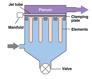 FIGURE 3. This is a general view of the filter plant and direct cooling chamber at Honshu I. The ceramic filter plant can be seen center left in the plant. To the right of the filter plant is the direct cooling chamber and to the left the exhaust stack |
Ceramic elements can be employed in a filtration plant to meet the particulate (dust) emission target across a broad range of processes. In this article, the terms filter plant and filtration plant refer to a full filter assembly consisting of the housing and filter elements (Figure 1). The filtration plant can be a new build, or ceramic elements can be retrofitted into an existing bag-house filter. The filter plant, housing the array(s) of ceramic elements, is often used in combination with dry scrubbing and is placed downstream of cooling or heat recovery apparatus.
In principal, the operation of ceramic filter plants is similar to fabric bag houses. The gas to be cleaned is typically drawn into the plant by an induced-draft fan such that the particulate matter being collected builds up on the outside of the elements in the form of a cake. The cleaned gas passes through the wall of the elements and into the plenum, the cake being periodically removed from the elements by a reverse-pulse mechanism. The rigid nature of the elements promotes surface filtration, which in turn results in low emissions and extended media life.
Ceramic elements have been applied to a wide range of services where the benefits of the technology can be utilized, for example the need for efficient filtration at an elevated temperature. Some of these applications are listed in Table 6.
| Air pollution control applications | Product collection/recovery applications |
|---|---|
| Waste incineration | Titanium dioxide production |
| Soil cleaning | Fumed silica production |
| Metals smelting | Carbon black production |
| Minerals processing | Catalyst manufacture |
| Foundry processes | Platinum smelting |
| Glass furnaces | Metal powder production |
| Cement production | Activated carbon production |
| Fluidized beds | |
| Boiler plant |
The waste incineration applications can be further sub-divided into a number of small- to medium-scale duties. These include clinical, chemical, petrochemical sludge, animal waste, laboratory waste, tires and building waste.
Japan’s incineration example
With an area of 147,000 square miles, a population of 127,000,000, and around two thirds of the land area being mountainous and forested, Japan’s relative lack of space has precluded dependence on landfilling for waste management. Japan has achieved creditable recycling rates for waste paper, tires, and aluminum and steel cans; and Japan has utilized incineration for many years.
Of the 51.6-million metric tons (m.t.) of municipal waste created in 1998, some 78% was incinerated in 1,800 incinerators. A further 400-million m.t. of industrial waste are handled by 3,300 privately owned industrial incinerators.
In the 1980s, the Japanese system for dealing with municipal waste, with its integrated recycling and incineration program, was looked upon as somewhat of a model for municipal waste management. However, in the 1990s the growth of incineration led to greater public and media awareness of the potential for pollution created by the many incineration facilities. Particular emphasis was placed on dioxin emissions with the dioxin family of chemicals being suspected of causing a range of health problems.
Tougher emissions regulations for municipal waste incinerators were introduced in 1997, which included a tighter standard for dioxins. The dioxin standard for waste incinerators in Japan is now in line with that specified in European regulations at 0.1 ng/Nm 3 TEQ (toxic equivalent). The standards for other pollutants, such as acid gases and particulates, are generally higher than those adopted in Europe. For instance, the particulate standard for municipal waste incinerators is 50 mg/Nm 3 while a higher figure is regulated for smaller incineration facilities, typically 100 – 150 mg/Nm 3.
Case study background. As with municipal waste, the incineration of building waste has been the subject of more stringent emissions legislation in recent years. Such waste is derived from the construction and upgrade of buildings. Due to the source of the waste, the composition is highly variable, and contains wood, paper, cardboard, plastics and metal. There are a number of building-waste incineration plants in Japan, most of which are new installations. The first of these plants, a new installation utilizing ceramic elements, was commissioned in May 2002.
During that project design stage the end user considered both PTFE on PTFE needlefelt as well as ceramic elements for the off-gas filtration medium. Given the similar price of the two types of media, ceramic elements were eventually selected due to their additional benefits over the PTFE medium, which include the following:
-
Temperature capability giving process latitude and “insurance” against temperature surges
-
Low emissions
-
Effective acid-gas scrubbing in combination with a dry sorbent
To date, three plants have been commissioned that utilize ceramic elements in the gas cleaning train — two on Honshu and one on Shikoku island. The first plant to be commissioned (referred to hereafter as Honshu I) is in the Chugoku region, the second plant is on Shikoku (Shikoku I) and the third plant also on Honshu (Honshu II). This case study focuses on Honshu I, but emissions test data, also included, have been made available for Honshu II.
Installation details. A simplified schematic diagram of the Honshu I plant is shown as Figure 2. Bulk waste is delivered to the plant and pre-sorted prior to being fed by mechanical loader into a shredder. Metal objects are removed by hand from the shredded material on the conveyor line, which feeds a hydraulically operated charging ram that feeds the primary combustion chamber.

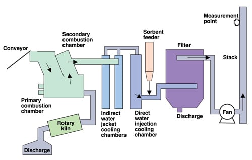 FIGURE 2. The Honshu incineration plant is shown here schematically |
Primary and secondary combustion is carried out at in excess of 1,270 K with further ash treatment in a rotary kiln to reduce final discharge volume. Combustion off gases are cooled by indirect, followed by direct cooling to accurately control temperature prior to sorbent injection.
Principal filter parameters are the following:
-
Element type: 3 m length · 0.15 m outer dia.
-
Number of elements: 324
-
Configuration: Vertically mounted 36 · 9 array
-
Filtration area: 453.6 m 2
-
Design gas volume: 20,000 Nm 3 /h
-
Designed filtration velocity: 1.41 m/min at 523 K
-
Sorbent: Slaked lime and activated carbon
Figure 3 shows a general view of the incineration facility and filter plant. The Shikoku I and Honshu II plants are similar in concept and operation to the Honshu I plant described above. Principal filter parameters for the Honshu II plant are as follows:
-
Element type: 3 m length · 0.15 m outside dia.
-
Number of elements: 216
-
Configuration: Vertically mounted 24 · 9 array
-
Filtration area: 302.4 m 2
-
Design gas volume: 10,000 Nm 3 /h
-
Designed filtration velocity: 1.06 m/min at 523 K
-
Sorbent: Slaked lime and activated carbon
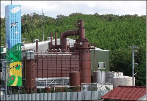
FIGURE 3. This is a general view of the filter plant and direct cooling chamber at Honshu I.
The ceramic filter plant can be seen center left in the plant. To the right of the filter plant is
the direct cooling chamber and to the left the exhaust stack
The plant is designed somewhat more conservatively than the Honshu I plant to give a lower operational face velocity.
Operational results. In order to be granted an operating permit, all three of the incineration installations had to undergo an official emissions test, based on isokinetic sampling, soon after commissioning. Results from these tests are presented to the plant operators with actual readings being compared to the regulations in force. The official test results from the Honshu I and II plants are presented in Tables 7 and 8. The acid-gas emission figures are a function of the sorbent being employed and its application. Residence time of the sorbent in the gas stream is crucial to allow acid species to react.
| Item | Unit | Value | |
|---|---|---|---|
| 1) Dioxin | ng-TEQ/Nm 3 | 0.00032 | |
| 2) Dibenzofuran | ng-TEQ/Nm 3 | 0.02296 | |
| 3) PCB | ng-TEQ/Nm 3 | 0.0000326 | |
| 4) 1) + 2) + 3) | ng-TEQ/Nm 3 | 0.023 | |
| 5) Total particulate | mg/Nm 3 | 0.3 | |
| 6) HCl | mg/Nm 3 | 2 | |
| 7) Sox | ppm | <1 | |
| 8) NOx | ppm | 120 | |
| 9) CO | ppm | 0 | |
| 10) O 2 | % | 10.6 | |
| 11) Moisture | % | 22.0 | |
|
12) Actual gas volume |
Wet Dry |
Nm 3 /h Nm 3 /h |
19,110 14,910 |
| 13) Gas temperature | o C (K) | 188 (461) | |
| Item | Unit | Value 3 | Regulation 3 | |
|---|---|---|---|---|
| 3. Empty cells mean either not measured or not regulated | ||||
| 1) Dioxin | ng-TEQ/Nm 3 | |||
| 2) Dibenzofuran | ng-TEQ/Nm 3 | 0.010 | ||
| 3) PCB | ng-TEQ/Nm 3 | 0.000010 | ||
| 4) 1) + 2) + 3) | ng-TEQ/Nm 3 | 0.01 | 0.1 | |
| 5) Total particulate | mg/Nm 3 | 0.1 | 250 | |
| 6) HCl | mg/Nm 3 | 45 | 700 | |
|
7) Sox |
Concentration Emission |
ppm Nm 3 /h |
28 0.34 |
10.44 |
| 8) NOx | ppm | 100 | ||
| 9) CO | ppm | 0 | ||
| 10) O 2 | % | 11.1 | ||
| 11) Moisture | % | 7.4 | ||
|
12) Actual gas volume |
Wet Dry |
Nm 3 /h Nm 3 /h |
13,000 12,000 |
|
| 13) Gas temperature | o C (K) | 134 (407) | ||
Future developments
Ceramic elements are employed in filter plants, either new or retrofitted, in much the same way as traditional polymeric filter bags. It has been demonstrated that ceramic filters offer practical operating benefits and commercial competitiveness in high-temperature processes where corrosion resistance and the ability to eliminate dust emissions are needed.
A further important development of this technology has seen the introduction of ceramic filter elements that not only deliver the dual benefits of high particulate-removal efficiency and temperature resistance, but also treat gaseous pollutants. Fairly recently, these benefits have been enhanced by the addition of a catalyst to the filter systems [ 2]. The catalyst can reduce NOx with efficiency up to 95%, with the addition of ammonia or urea, and destroy VOCs as well as dioxins. This new technology has potential for application where particulate and NOx control are needed in tandem, and is competitive with electrostatic precipitators and standard selective catalytic reactors, particularly in the power generation, glass and cement industries.
Edited by Dorothy Lozowski
References
-
Ondrey, G., Some Filters Like it Hot, Chem. Eng., November 2001, pp. 29 – 39.
-
Ondrey, G., Remove dust and pollutants with this catalytic filter, Chem. Eng., July 2005, p.16.
 |
Authors
|
 Gary Elliott is the general manager of Clear Edge Filtration’s (formerly Madison Filter) Cerafil Division (Clear Edge UK Ltd., The Stable, Rock Farm, Seckington, Tamworth, B79 OLA, U.K.; Phone: +44–1827–839125; Email: Gary.Elliott@clear-edge.com). After graduating with a B.S. degree from Leicester University, Elliott worked in the field of high temperature ceramic in the metallurgical field, and more recently in the field of gas filtration. Elliott has specialized in applying ceramic filters to industrial gas filtration for pollution control duties as well as for process filtration and product collection.
 Andrew Startin is the product manager at Clear Edge Filtration’s Cerafil Division, where he is responsible for technical and business development aspects of Cerafil. He graduated in 1981 from Brunel University (London, England) with a degree in materials science and technology. From there, he joined Doulton Industrial Products in Stone, Staffordshire where he worked on projects developing industrial ceramics primarily for the aerospace industry. He then joined Ashland Chemicals and followed by Universal Abrasives where he was involved in further development work on technical and industrial ceramics. In 1990 Startin joined Foseco, Birmingham, and first became involved with Cerafil ceramic filter elements in 1992. He became a full time member of the Cerafil team in 1994.