Significant improvement in reducing fluid loss, optimizing flow paths and easing operation are among the advances in next-generation coupler technologies
According to the National Response Center’s (NRC) “Spills and Accidents” database, which collects data on toxic chemical spills and other accidents ranging from an oil sheen on water to the release of thousands of gallons, there were a total of 26,987 reported spill incidents in the U.S. in 2015. State-by-state, they ranged from a high of 3,228 reported events in Louisiana to a low of 35 incidents in South Dakota.
Across those state-specific numbers, 42% of the spill events involved mobile vehicles, 30% took place at a fixed site and 11% occurred at a storage tank, platform or pipeline. In other words, those three categories accounted for 83% of the total number of incidents in 2015. Looking at the causes of these chemical spills and accidents, 24% were due to equipment failure, while operator error and transport accidents both accounted for 7% of the total.
Knowing these numbers, it’s not hard to imagine a great deal of sleepless nights for the people who manufacture, store, transport, dose, blend, mix, bottle and package finished chemical products or their feedstocks as the ever-present threat of a catastrophic spill hangs precariously over their heads. The complexity of chemicals processing facilities (Figure 1) demands excellence with regard to safety and security. Because of the many transfer points in the manufacturing and handling supply chains in the chemical process industries (CPI), operators must constantly ensure that their liquid-transfer equipment and loading systems are of the highest quality and reliability.
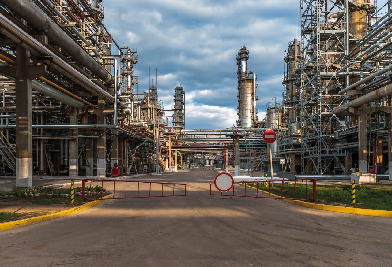
FIGURE 1. CPI site operators must be certain that the liquid-transfer equipment and loading systems they employ, including dry-disconnect couplers, constantly meet the highest levels of quality and safe, reliable operation
This includes the loading arms, hoses and disconnects that are used to transfer chemical products and feedstocks from, for example, barges, railcars, transport vehicles and pipelines to storage tanks, and from production lines to bottling, packaging and tote-filling operations. This article details the operation of various types of dry-disconnect couplers, and illustrates how selecting the proper style of coupler can help increase safety, optimize flowrates and prevent the types of costly and dangerous chemical spills or accidents that the NRC so fervently monitors.
Poppet-Style Versus Ball-Valve Dry Disconnect Couplers
The differing operational mechanisms of poppet and ball-valve dry-disconnect couplers are described in the sections below.
Poppet Style Design
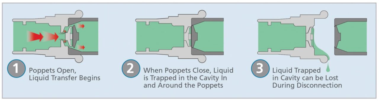 When utilizing poppet-style disconnects, liquid transfer is initiated when the poppets are opened by the operator (Step 1). The liquid transfer is completed when the operator closes the poppets (Step 2). However, at this time, a small amount of liquid can be trapped, and during disconnection, it is possible that the trapped liquid can escape, leading to a minor product spill (Step 3).
Ball-Valve Style Design
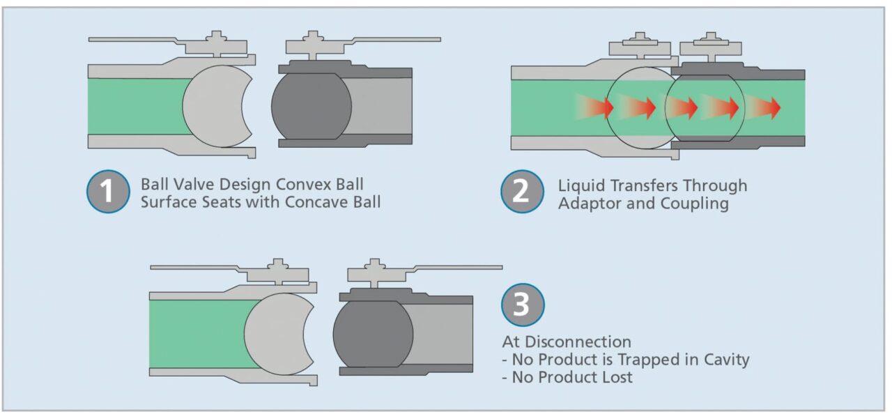 The operation of double ball-valve dry disconnects allows a convex ball to seat with a concave ball when the valve is opened (Step 1). This straight-through design allows the liquid to transfer through the adaptor and coupling with no reduction in flowrate (Step 2). Upon disconnection there are no cavities created in which product can nest, meaning no product will be spilled. This no-spill operation is accomplished through the use of five independent and redundant mechanical interlocks that require deliberate sequential action by users, thereby eliminating unintentional spills and catastrophic chemical releases.
Know what is needed
In general, designing and constructing a loading system for chemicals is a complex process. Many different variables must be accounted for, and no two systems are ever exactly alike. For example, will finished products or raw feedstocks be loaded onto or unloaded from railcars, barges, pipelines or tanker trucks? Will the loading and unloading take place from bottom outlet valves on the transport vehicles, or will they be top-loading operations, which will require the use of loading arms and support structures? All of these questions are critical considerations and their answers will help determine which specific loading-system components will be required. This also means that the engineers who fashion these systems and their individual components must work closely with users to create systems that meet unique needs, while also building units that deliver reliability and safety. Before a loading system is ever installed and the first ounce of chemical transferred, the following are some of the most important operational considerations that must be taken into account:
- Is it a top-, bottom- or side-loading application? Knowing the configuration will help determine the overall design of the system
- What are the ambient weather conditions where the system will be used, and will the equipment encounter extremely cold or hot temperatures? Environmental conditions must always be taken into consideration when working with chemicals that possess unique traits
- Do the products being handled produce extreme temperatures that must be accounted for? If so, proper metals and elastomers for these temperature conditions must be used
- What type of products will the loading system be used for? Temperature, corrosiveness and viscosity are just some of the considerations here
- Will any type of cleaning or purging procedure be employed?
- What materials of construction (metals, elastomers and so on) are most compatible with the products to be handled? Materials that are not compatible with products to be handled are more susceptible to failures that can lead to catastrophic spill incidents
- How long must the loading arms be? The precise dimensions of the loading system must be known and the system designed to exactly meet those parameters
- Will railcars or trucks need to be spotted from various distances, requiring more flexibility?
- What level of product flowrates will be required? Loading and unloading times must be optimized, especially at facilities where high volumes of finished products and feedstocks must be transferred on a daily basis
- Will any specialized welding be needed for the job? More specifically, is it a hygienic or sanitary application that requires a special weld procedure to ensure that there is no buildup of bacteria on the interior of the loading arm or its components?
- What is the design of the support structure, and is it capable of handling heavier, longer loading arms?
- Are there any specialized material-handling requirements that must be accounted for? For example, will the system be handling a chemical that can explode in the presence of air, which would necessitate an entirely leak-free operation?
- Is the loading system ergonomically designed so that it is not only safe for the application, but also minimizes the physical demands on the operator?
While all of these questions are crucial to designing the proper loading system, many operators, oftentimes by necessity, are known as “first cost” equipment buyers, meaning that they look for equipment with a low initial cost, regardless of brand or quality. However, while the initial cost may be low, these operators can expect higher costs on the back end in the form of increased maintenance and downtime, service and replacement charges, not to mention the incalculable cost incurred if a high-profile incident occurs, such as an equipment failure that results in the leak of a hazardous chemical. Another item to consider is the potential damage to the environment and the facility’s reputation that can occur when failing equipment results in a product leak that can lead to personal injury or contamination to the air, soil or groundwater.
Facility operators who are quick to embrace low initial cost for their loading-system purchases would be wise to first conduct a lifecycle cost analysis (LCA) for their site. This would include not only the “first cost” of the equipment, but cost estimates for any subsequent maintenance, service and replacement instances that can result in excessive loading-system downtime or an environmental incident. Those that do complete an LCA will find more often than not that choosing equipment based on quality construction is a much better choice than relying solely on price first.
Even after acknowledging and addressing the questions that must be considered before deciding on the proper loading system for the operation, finding the operational optimum in manufacturing and handling requires many specific steps to be completed succinctly and reliably. Consider the transfer of liquids in the process — as mentioned, there are many specific transfer points that must be taken into account, and throughout the myriad liquid-transfer processes, chemical manufacturers and handlers aim to optimize two critical areas: the safety of production personnel and the environment; and the time needed to complete the manufacturing process.
Ensuring personal and environmental safety is important because not only the end products, but also many of the raw materials used in chemical manufacture, can be volatile, hazardous or corrosive — from general categories like acids and solvents to more specific formulations such as butadiene, xylene and toluene — so they therefore must be treated with the utmost respect and properly contained.
Additionally, preventing spills or leaks is vital because any that occur, besides being dangerous on various levels, have the potential to interrupt the production schedule, which not only delays product completion, but can also lead to the loss of high-value, expensive ingredients and the incurrence of prohibitive cleanup costs.
Plunging ahead
When considering the dry-disconnect couplers that will play an important and prominent role at the end of hoses and loading arms in the safe transfer of hazardous chemicals and their feedstocks, a certain type of technology has charged to the forefront over the years. This technology is referred to in the industry as either a bayonet-and-plunger or poppet style dry-disconnect coupler.
The bayonet-and-plunger dry-disconnect coupler technology has gained acceptance because its design and operation possesses a number of benefits for the user. Most importantly, there is relatively little fluid loss when the coupler is disconnected — as little as 0.5 mL of fluid, or the equivalent of 1/10th of a teaspoon. These couplers are also generally equipped with safety locks that prevent the coupler from opening accidentally as the liquid is flowing through it.
Most brands of bayonet-and-plunger couplers are lightweight and easy to maneuver, which eliminates undue operational stress and strain on hoses and loading arms, as well as the person operating the loading system. Their low cost also makes them attractive to manufacturers who are looking to streamline capital expenditures and protect the operation’s bottom line.
With all that being said, bayonet-and-plunger couplers do have several operational characteristics that can potentially limit their optimal application in chemical manufacturing settings. First, while an extremely small amount of fluid may be lost during disconnection, there are other coupler technologies that have been proven to lose less fluid.
From an operational standpoint, the biggest shortfall of bayonet-and-plunger couplers is their internal design, which puts a number of parts in direct contact with the fluid flow. Any type of flowrate restriction will negatively affect the production process. For example, if an engineer specifies a 2-in. line and a bayonet-and-plunger coupler with a 2-in. I.D. is installed, the flowrate will actually be less than what is to be expected from a free-flow 2-in. line because the liquid will have to work its way around the coupler parts that it comes into contact with. This may also necessitate the installation of a larger-than-necessary 2.5- or 3-in. coupler, which can be more expensive.
Additionally, the bayonet-and-plunger coupler’s internal components (things such as springs, guides and poppets) can also create areas where the liquid can collect and nest, which makes it difficult to clear the lines and maintain a clean pumping environment. This is especially true when handling liquids with higher viscosities.
Bayonet-and-plunger couplers can be at a disadvantage when manufacturers choose to incorporate a closed-loop fluid-transfer system. The drawback is that in a closed-loop system, there may be numerous valves deployed, meaning that, at some point, the closing of two valves will leave product trapped in the hose between the closed valves. The pressure that is created when the downstream valve is subsequently opened has the potential to damage the dry-disconnect coupler downstream of it, which can lead to leaks and product spills.
Lastly, bayonet-and-plunger couplers are harder to repair or maintain inline because of the number of parts they contain. In fact, many bayonet-and-plunger suppliers require the coupler to be removed and returned to the manufacturer for repairs. If the coupler can be repaired in the field, the number of steps in the repair process, along with the number of parts to consider, can make it difficult or confusing for the maintenance technician, which could result in a repair job that leaves the coupler vulnerable to less than optimum operation and an increased risk of leaks or spills.
Double ball-valve couplers
In addition to bayonet-and-plunger dry-disconnect couplers, an emerging coupler technology is the low-spill dry-disconnect coupler (Figure 2) that operates via a double ball-valve design. This technology features a convex ball that rests in a concave ball, resulting in the elimination of any cavity between the mating halves. This guarantees that no residual fluid will be trapped there, lowering the risk of spills and giving the liquid virtually no place to collect or hide, which eases cleaning. The box on page 55 compares the differing flow mechanisms of double ball-valve and poppet-style dry-disconnect couplers.
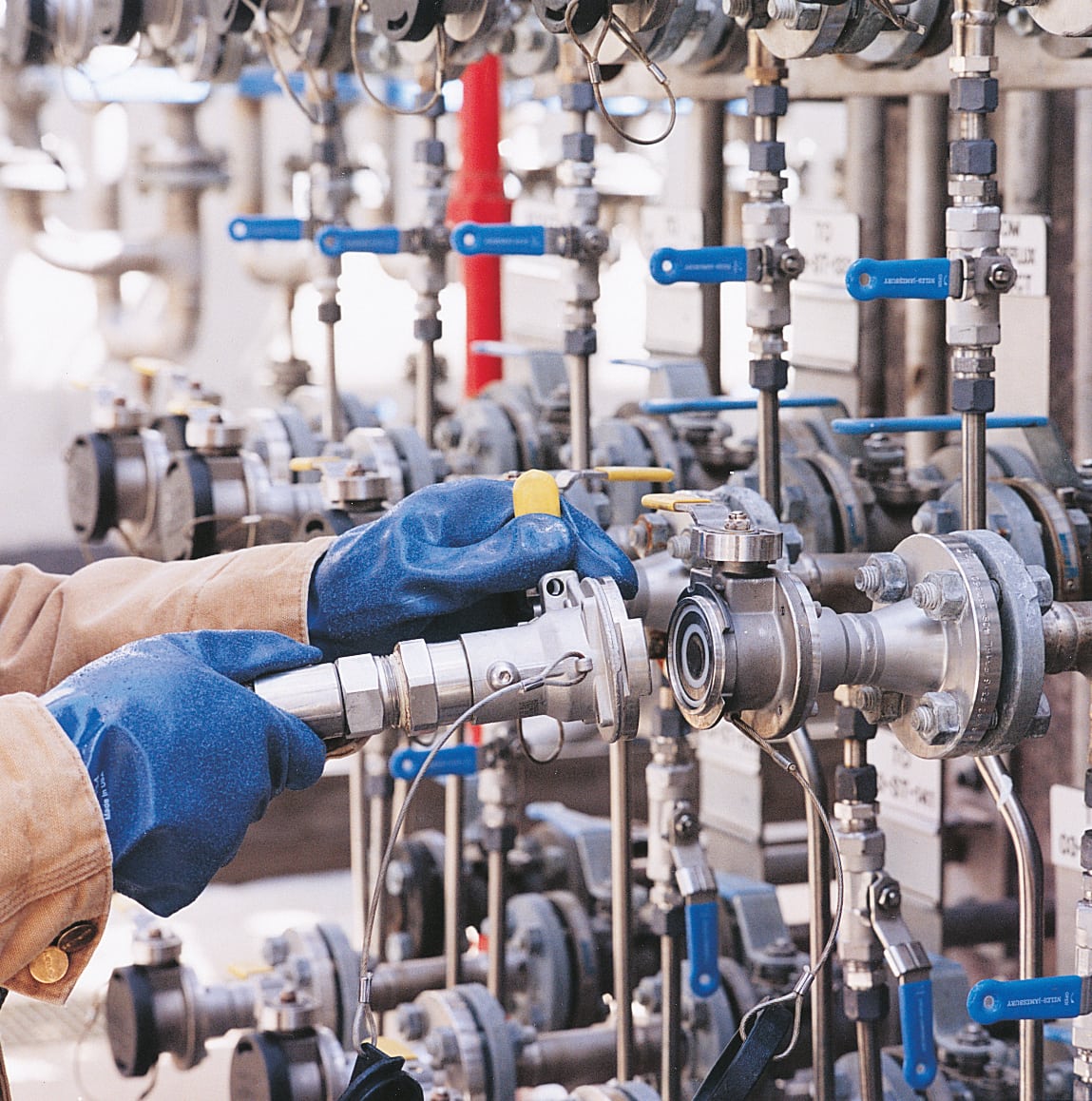
FIGURE 2. Numerous variables and components must be carefully considered when designing a loading system to ensure that leaks are kept to
a minimum
The double ball-valve design also incorporates multiple safety interlocks that allow the valve to open and close only through a deliberate action by the user. This prevents any accidental opening of the valve, which lowers the risk of unintentional spills and catastrophic chemical releases. This is not only critical when transferring raw materials from large storage vessels, but also during the numerous tote-filling operations that are a staple of chemical manufacture. This constant on-and-off filling of smaller-capacity containers can put undue strain on the couplers, but the double ball-valve design and unique method of operation nullify the harmful effects.
The ball-valve design of the coupler also enables it to offer an unrestricted flow path (Figure 3), which minimizes pressure drop. In other words, a liquid-transfer system that calls for a 2-in. hose can utilize a 2-in. double ball-valve coupler model without any reduction or restriction to the required flowrate. In addition to allowing the plant operator to correctly size his or her equipment, an unrestricted flow path optimizes flowrates, resulting in faster loading and unloading times and a more efficient and cost-effective operation.
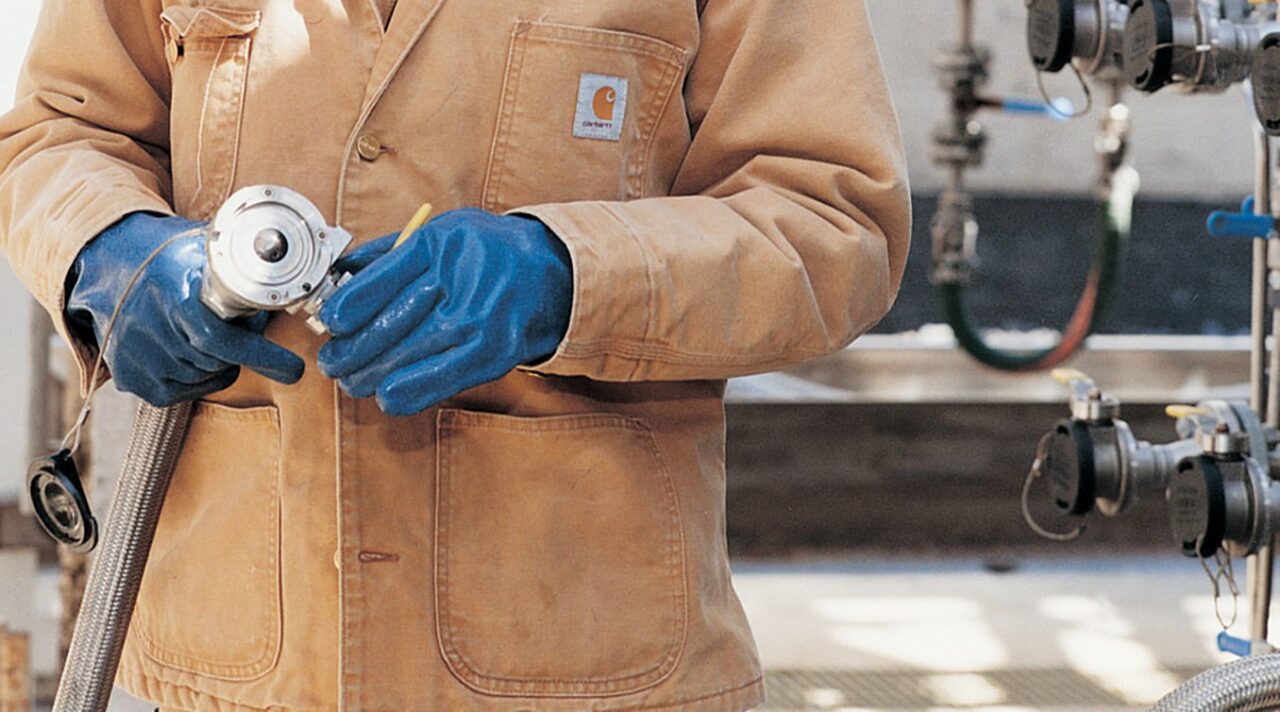
FIGURE 3. Maximized product flowrates and shutoff reliability in the coupling connection allow for improved product containment
Since the design of double ball-valve couplers incorporates fewer parts than poppet-style technologies, they can be repaired onsite, with no need for time-consuming returns to the manufacturer or in-the-field repair personnel to battle with complicated and confusing repair or maintenance instructions.
Secure product handling is key for full containment. For extremely product-sensitive operations, the double ball-valve-style dry-disconnect coupler offers a keyed interface option that locks out and isolates transfer lines. This means a specific coupler can only be used with a specific hose or loading arm. This capability helps prevent cross-contamination of liquids at sites where numerous unique formulations are handled extensively, and must be transferred through common piping systems.
Achieving safe operation and cost-effectiveness is a day-to-day challenge for chemical manufacturers and handlers, especially when both the finished products and raw materials are hazardous and expensive. With many production operations requiring large tank farms and the transfer of thousands of gallons of raw materials and end products on a daily basis, the type of dry-disconnect coupler used, and the technology’s ability to optimize reliability, safety and cost is a critical consideration.
A careful understanding of the operational advantages of different dry-disconnect technologies — including leak-free product containment and ease of repair and maintenance — will enable manufacturers and handlers to achieve a peace of mind and hopefully decrease the workload of organizations like the National Response Center. ■
Edited by Mary Page Bailey
Author
 David Morrow is a veteran designer of bulk liquid-handling systems presently employed as director of product management for OPW Engineered Systems, part of Dover Corp.’s OPW division (2726 Henkle Drive, Lebanon, Ohio, 45036; Phone: 513-305-2059; Email: David.Morrow@opwglobal.com; Website: www.opw-es.com). His nearly 20-year career working in difficult liquid-transfer applications has included varied experiences ranging from bottom-loading petroleum in China to acids in Germany to crude oil in South Dakota. Morrow graduated from the University of Cincinnati.