Several aspects of crossflow membrane filtration, including process design, equipment selection and control, are detailed here
A membrane, also referred to as a semipermeable membrane, is a thin layer of material that selectively passes one or more components of a feed solution or slurry, while retaining the others. Biological membranes have existed since the dawn of time, but synthetic membranes are of greater industrial importance. These were first employed commercially in crossflow filtration operations in the 1960s, and growth in the ensuing years was remarkably fast. Today, crossflow membrane filtration (CMF) is a major unit operation that is pervasive in numerous industries.
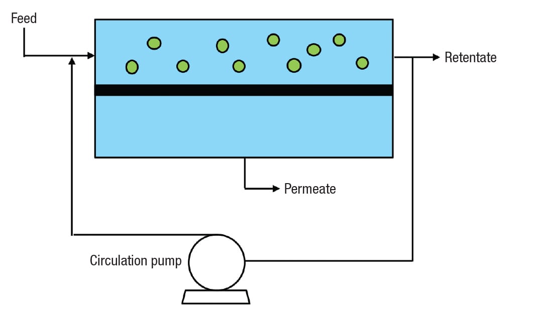
Figure 1. Crossflow membrane filtration (CMF) differs from conventional filtration in that feed flow is parallel to, rather than perpendicular to, the filtration surface
The concept is illustrated in Figure 1. Unlike conventional filtration [ 1], feed flow is parallel to, rather than perpendicular to, the filtration surface. During a given pass, only a small portion of the feed permeates the membrane and becomes permeate, while a much larger portion is retained as retentate. Most of the retentate is returned for multiple passes, by the action of the circulation pump. This allows a high linear velocity, which imparts a shear to the membrane that helps to keep the filtration surface clean. The valuable stream may be the permeate, the retentate, or both.
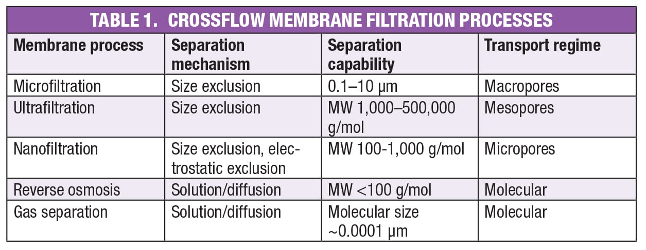
As shown in Table 1, membrane pore size varies considerably, with separation capabilities from angstroms (Å) to several microns (μm) in particle size. The relatively coarse microfiltration (MF) membranes are used to separate liquids from undissolved solids by size exclusion, as in traditional filtration processes. In principle, the liquid composition does not change, although in some cases there are phenomena other than size exclusion that do lead to retention of dissolved species, including adsorption onto the membrane surface or the undissolved solids themselves. The relatively large pores characteristic of microfiltration membranes are known as macropores.
Like microfiltration, ultrafiltration (UF) operates using traditional size exclusion, but with smaller mesopores rather than macropores. While both UF and MF are used to remove undissolved solids, UF membranes are also capable of separating large and small molecules in solution. UF membranes are described by their nominal molecular weight (MW) cutoff (NMWC), which is a rough indication of the smallest molecule that the membrane will retain. However, because permeability depends on more than just molecular size, exclusion of all molecules above a certain NMWC is unlikely. As a rule of thumb, for complete removal of molecules of a given size, a membrane rated one-tenth that size should be selected. Ultrafiltration membranes are available with NMWCs of 1,000 to 500,000.
This article focuses on MF and UF, except for a brief mention of the other processes listed in Table 1. Nanofiltration membranes contain micropores that are tight enough to separate very small molecules, such as monosaccharides from disaccharides. For neutral molecules, the principle is size exclusion, the same as in UF and MF, with NMWCs of 100–1,000. However, nanofiltration membranes can be functionalized with charged groups, making electrostatic interactions an important factor in performance. Such membranes are used, for example, to repel anions in wastewater treatment applications. Nanofiltration is a relatively new classification — before the term was coined, these products were considered loose reverse osmosis membranes.
Reverse osmosis membranes were the first to see large-scale industrial use, primarily for desalination of seawater. Unlike the membrane processes discussed so far, the separation mechanism is solution/diffusion, meaning molecules dissolve in the polymeric membrane, then pass through by diffusion. In desalination, the most common application, the electrostatic attraction between ions and surrounding water molecules leads to hydrated structures that dissolve and diffuse much more slowly than free water molecules. For this reason, the free water passes through, while the ions are largely rejected. RO membranes are non-porous, meaning there are no distinct pores that accommodate fluid flow. The openings are the interstitial spaces between the polymer chains, and the transport regime is known as molecular because the size of these openings is of the same order of magnitude as the small molecules (nominally, molecular weight less than 100 g/mol) that pass through these membranes.
Finally, the tightest membranes are those used for gas separations — for example, separation of air into nitrogen and oxygen. These non-porous membranes also fall into the molecular transport regime, and pass molecules on the order of 0.0001 μm in size.
Advantages and disadvantages
The main advantage of crossflow membrane filtration is the shear imparted to the filtration surface, which reduces fouling by particulate matter or retained molecules. Another advantage is ease of scaleup, which is linear and straightforward. Pilot work is done with one or a few modules identical to those to be used in production, which minimizes scaleup risk. The required number of production modules is easily calculated from the target production rate and the permeate flowrate per unit filtration area, or flux, obtained in the pilot plant. Other advantages of CMF are: mild processing conditions (temperature, pressure); high product yield; ability to operate as a closed system, reducing risk to personnel and the environment when handling hazardous materials; and the ability to tailor membrane properties to match specific user requirements.
On the downside, the capital cost of membrane plants is relatively high, especially if exotic membrane materials are required. In addition, many polymeric membranes are subject to swelling in the presence of high concentrations of organic compounds, and cannot be operated at high temperatures. These challenges can be met with inorganic materials or high-performance polymers, but the cost is higher. Other disadvantages include formation of a polarization layer on the membrane surface, which reduces flux; fouling, requiring periodic cleaning; and in some cases, significant dilution when retained species are washed to increase product yield or remove contaminants — a process known as diafiltration.
Batch process flowsheet
A process flowsheet for a batch or semi-continuous membrane filtration process (continuous processes are discussed later) is shown in Figure 2. Please note that this is just an example. Like any chemical engineering unit operation, CMF processes vary widely in complexity, ranging from completely manual to highly automated. In a batch process, retentate is circulated through the membrane module then back to the feed/retentate tank, where the volume gradually decreases, and the concentration of the retained species increases, as permeate is removed. In a semi-continuous process, fresh feed is added to the tank at the same rate permeate is withdrawn, so that the retentate concentration still increases while the tank level remains constant.
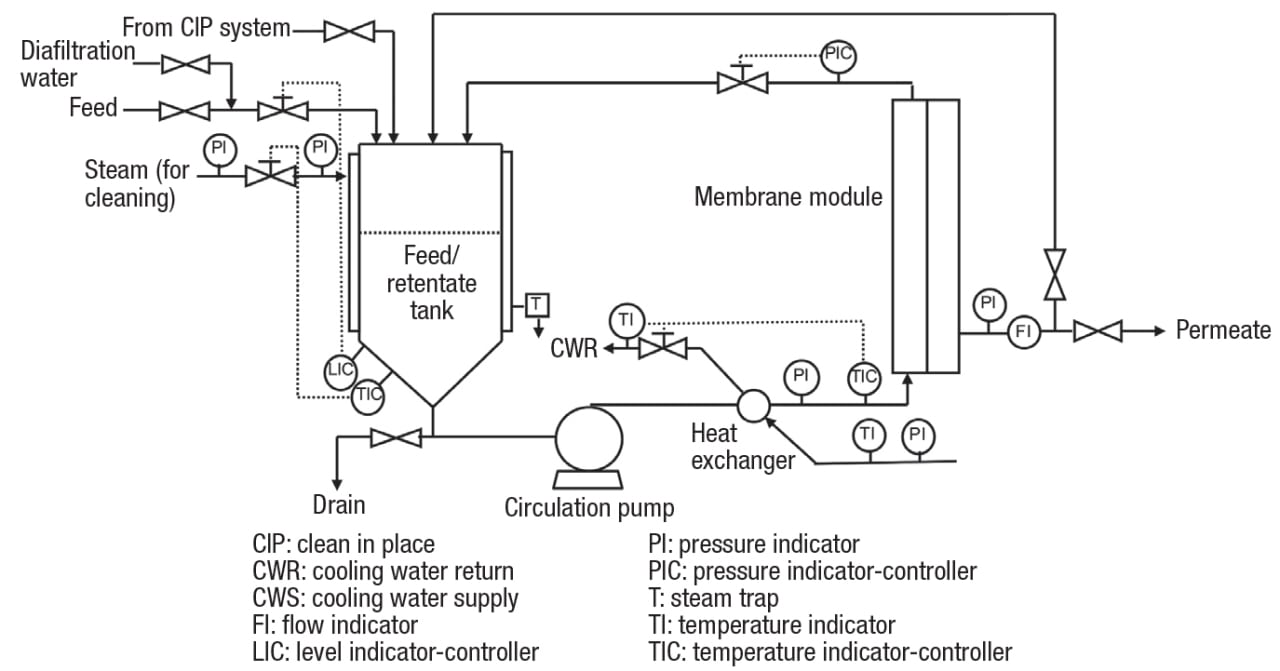
Figure 2. Batch or semi-continuous crossflow membrane filtration processes can vary widely in complexity, depending on the application
The pressure driving force, known as transmembrane pressure (TMP), is generated by the combined action of the circulation pump and the throttling valve downstream of the module. These must be balanced to maintain a stable operation. For example, throttling the valve will increase the transmembrane pressure, which tends to increase the flux (up to a point — this is discussed further later in the article). At the same time, the flowrate will decrease, and the reduced shearing action will result in a lower flux.
Note that in Figure 2, the pump discharge is cooled. This may seem counterintuitive, because in most cases, a higher temperature results in a lower viscosity, and in turn, a higher filtration rate. However, the circulation pumps used in crossflow membrane units are rather large, and generate a significant amount of heat. For this reason, cooling may be needed to avoid damage to the product, or in the case of common polymeric membranes, remain below the maximum allowable operating temperature. This is especially true in a batch process when the retentate volume becomes small. Cleaning is done without the need for disassembly, a feature known as clean in place (CIP), which is common in food and pharmaceutical applications. The indicated ability to recycle permeate to the feed/retentate tank is useful during certain portions of the CIP cycle.
MF and UF basics
Microfiltration membranes, which are used to produce clear permeate from slurries containing solids as large as 10 μm, typically have ratings of 0.1, 0.2, 0.45 or 0.65 μm. Required transmembrane pressure is low, usually 10–50 psi — as explained later, higher is not necessarily better. Volume reduction is typically 5–12, corresponding to undissolved solids of 100–700 g/L in the retentate. Greater volume reduction and higher retentate solids are achieved with rigid, incompressible solids than with soft or gel-like materials that are more difficult to handle. A partial list of applications of crossflow membrane microfiltration (CMMF) is given in Table 2.
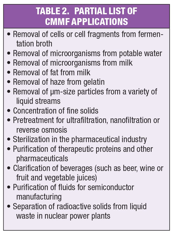
In addition to the general advantages of CMF cited previously, CMMF offers a permeate that is completely solids-free, and typically more clear than filtrates from conventional filters [ 1] or centrifuges [ 2]. Moreover, no filter aids or other processing aids are needed. Disadvantages are the inability to produce a cake, as well as possible pluggage of membrane pores with compressible solids. However, if macromolecules are not needed, the latter issue can be overcome with the use of a coarse ultrafiltration membrane, with pores large enough to pass all but the largest dissolved molecules, yet sufficiently small to exclude undissolved solids. This technique is used, for example, in the filtration of apple juice.
Operating pressures in ultrafiltration are higher than in CMMF, but still relatively low. If undissolved solids are not present, volume reductions of 30 or higher are possible, much higher than those achievable with CMMF. The limitation may be the retentate viscosity, the solubility limit of one or more components or the practical problem of equipment holdup — that is, enough retentate is needed to fill the pipes and avoid pump cavitation. Ultrafiltration is widely used in the food industry— for example, to concentrate proteins in skim milk or cheese whey. The process is also commonly used in drug purification and other pharmaceutical applications, as well as water purification and chemical recovery in the textile, paper and waste-treatment industries.
Pressure effects and polarization
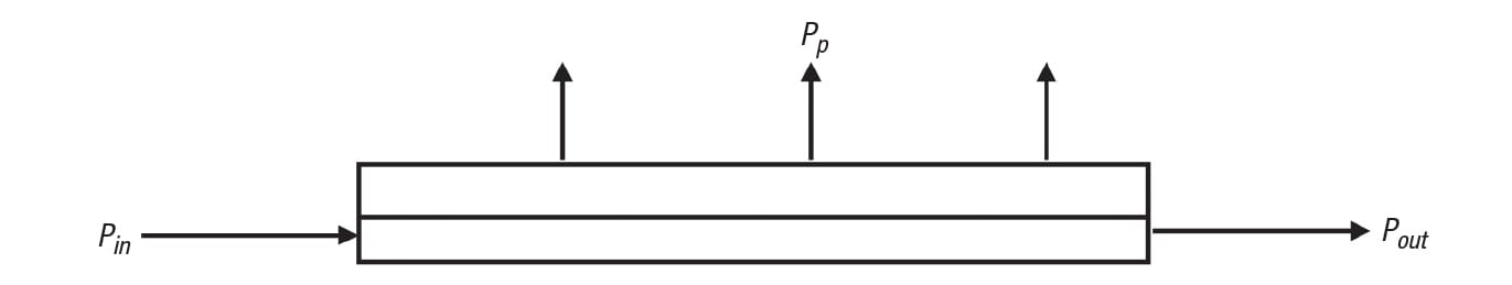
FIGURE 3. The pressure profile within a CMF module is an important factor to consider. Here, Pin is the feed/retentate pressure at the module inlet, Pout is the feed/retentate pressure at the module outlet and Pp is the permeate pressure
As with normal pipe flow, friction causes a loss in pressure from the inlet to the outlet of the module on the feed/retentate side. Referring to Figure 3, this pressure drop due to bulk fluid flow is expressed as in Equation (1) below:
∆ P b = P in – P out (1)
This is not to be confused with transmembrane pressure, which is the difference between the average feed/retentate and permeate pressures, as shown in Equation (2):
∆ P tm = [( P in + P out)/2] – P p (2)
Often, the permeate pressure is close to atmospheric, just high enough to overcome the friction loss in the downstream piping. Intuition tells us that a higher TMP results in a higher flux, and this is generally the case, up to a point. However, above some threshold value — typically about 1 bar — a polarization or gel layer forms on the membrane surface [ 3]. This layer is composed of undissolved solids and retained molecules in the feed. Moreover, because retained species concentrate near the membrane surface, precipitated components may be present if their solubility limit is reached.
Once the polarization layer is established, a further increase in TMP does not increase the flux, and may even reduce it. In addition, the polarization layer actually does the filtration, and the membrane itself has little effect on the permeate composition. To minimize the effect of the polarization layer and maximize the flux, TMP should be kept relatively low — typically 10–15 psi for MF, and up to 50 psi for UF. For applications that are particularly sensitive to fouling, much lower TMP values are used, as low as 1–2 psi. These low TMPs require backpressure on the permeate side, an exception to the general practice of operating with the permeate near atmospheric pressure.
![Figure 4. The flux (in liters of permeate per square meter of membrane area per hour, or LMH) versus transmembrane pressure (TMP) for microfiltration of corn starch hydrolysate at two different linear velocities is shown [4]](https://www.chemengonline.com/wp-content/uploads/2017/04/FR3_4.jpg)
Figure 4. The flux (in liters of permeate per square meter of membrane area per hour, or LMH) versus transmembrane pressure (TMP) for microfiltration of corn starch hydrolysate at two different linear velocities is shown [4]
Evidence of the polarization layer is clear in Figure 4, which shows flux versus TMP for microfiltration of corn starch hydrolysate at two different linear velocities [ 4]. These data were collected at a concentration factor of one, meaning all permeate was recycled. At low values of TMP, the flux increases linearly with TMP, as one might expect. However, the curves begin to level off at about 25 psi, and above 30 psi there is no increase in flux upon further increase in TMP. Note that the maximum flux is higher at the higher linear velocity, because the higher shear reduces the thickness of the polarization layer, and in turn, the resistance to flow.
Membrane operation with an established polarization layer is illustrated in the inset in Figure 4. The retained species is transported from the bulk feed/retentate to the polarization layer by convection. The concentration of the retained species in the polarization layer increases, and this gradient drives diffusion back into the bulk. At steady state, the rates of transport to and away from the polarization layer are equal, and the polarization layer is stable. An increase in pressure causes an increase in the rate of convective transport to the layer, which leads to an increase in the retained species concentration, and in turn, increased rate of diffusion back into the bulk. A new steady state is established, and the net result is no change in flux, consistent with Figure 4.
Design considerations
Important design considerations include not only most or all of the considerations pertinent to the design of traditional filter or centrifuge operations, but also some that are unique to membrane systems. Key factors are described in the following paragraphs.
Productivity target (usually expressed as annual throughput).As with any chemical engineering unit operation, this figure forms the basis of membrane process design and economics. For example, throughput drives the choice of batch or continuous processing, with larger volumes making the latter more cost effective. Once the permeate flux is known from pilot work, the membrane area needed to reach the productivity target is a straightforward calculation, as mentioned above.
Fluid physical properties (especially viscosity). In most cases, flux decreases with increasing viscosity. For this reason, membrane processes are sometimes operated at elevated temperatures, with due consideration of the heat generated by the circulation pump. As discussed below, membranes made from inorganic materials and certain polymers allow operation at temperatures well above the limits of traditional polymeric membranes. However, the rate of membrane fouling may also increase with temperature, and this can negate some or all of the benefit. In addition to the change with temperature, any increase in viscosity with retained species concentration must also be taken into account.
Fluid composition. The starting concentration and solubility of retained molecules clearly have an impact on design — for example, they affect the achievable retentate concentration and, barring other limitations, volume reduction. If undissolved solids are present, not only is their concentration important, but also the nature of those solids. As with conventional filtration, rigid, spherical particles are more easily removed than ones that are soft, gelatinous or odd-shaped. Interactions between the feed and the membrane material also warrant consideration. For instance, components of interest can be lost if adsorbed onto the membrane surface. In this case, the designer must either select a membrane material with little affinity for the solute, or if possible, change the processing conditions (for example, pH) to reduce affinity.
Fouling tendency. Membrane cleaning adds cost, attributable not only to the required chemicals, but more importantly, to the associated downtime. Membrane materials, operating conditions, cleaning protocol, and where possible, feed properties, must be selected to minimize fouling, and in turn, cleaning time and frequency. While the feed composition gives some clues about expected fouling tendency, longterm pilot testing is needed to develop a full understanding.
Modules. The module specifications are a key part of membrane system design. Available module configurations are discussed in subsequent sections of the article. Specifications include module length, diameter, size and location of ports, internal dimensions, materials of construction, and of course, membrane filtration area. Key operating specifications are temperature, transmembrane pressure and linear velocity. The latter is typically 1–2 and 5–7 m/s for polymeric and inorganic membranes, respectively. The benefit of the increase in flux with linear velocity (shown, for example, in Figure 4) is at least partially offset by the higher pumping cost. Thin channels offer higher membrane area per unit volume (that is, packing efficiency), but these are not suitable for streams with high viscosity or undissolved solids content. Those situations require wider channels, and in turn, lower packing efficiency.
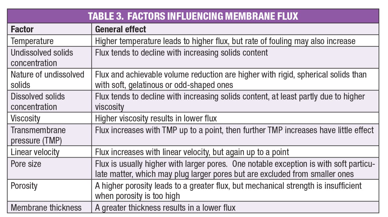
Flux. Clearly, an important number in membrane system design is the flux, usually expressed as liters of permeate per square meter of membrane area per hour (LMH), or gallons per square foot per day (GFD). A similar performance measure is permeability, or flux per unit transmembrane pressure — for example, LMH per bar. Factors influencing flux and permeability are listed in Table 3. The goal of pilot testing is to quantify these effects, particularly those of transmembrane pressure, linear velocity and retained species concentration.
Membrane materials
In the early days of crossflow membrane filtration, most membranes were made from cellulose acetate, and this polymer is still used. However, its chemical resistance is limited, pH tolerance is only in the range from about 2 to 9, and the maximum allowable temperature is relatively low at 35°C. Since the advent of membrane filtration on an industrial scale, there have been considerable advances in polymer technology. Today, there are a variety of robust polymeric membranes that can operate at pH values ranging from 1 to 14, and in some cases, at temperatures of 120°C or even higher. Examples include polysulfone (PS), polyethersulfone (PES), polyvinylidene fluoride (PVDF), polyacrylonitrile (PAN), polyamides, polytetrafluoroethylene (PTFE) and polypropylene (PP).
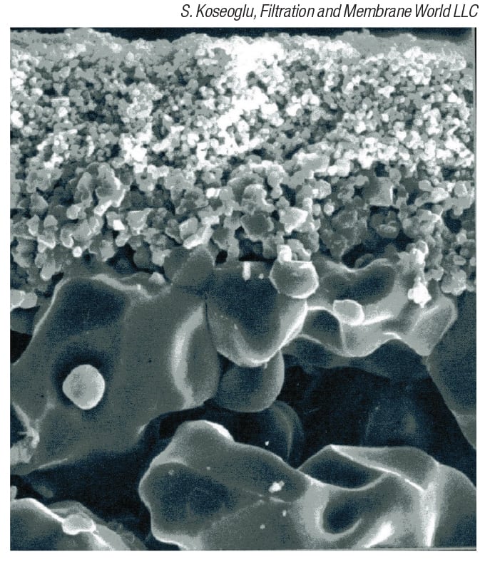
Figure 5: Asymmetric membranes, such as the one shown in this electron micrograph, are characterized by a thin selective layer on top of a more open support layer
Most of these membranes are asymmetric, characterized by a thin selective layer on top of a more open support layer (Figure 5). The tight selective layer, also called the dense, active or skin layer, does the actual filtration. Once this is done, a tight structure is no longer needed, and use of an open support minimizes the resistance to flow, while still providing the required mechanical integrity. A sublayer of intermediate pore size is also used in some cases. There are also symmetric membranes that contain pores with a uniform cross-section. These offer greater mechanical strength and longer life than asymmetric membranes, but the flux is lower.
Inorganic membranes are also available. These include ceramics, such as α-alumina, zirconia and metal oxides (notably, titanium dioxide), sintered stainless steel and graphite. Inorganic membranes are more robust than most polymers, able to withstand strong acids, bases and other corrosive chemicals, as well as high temperatures and pressures. Such membranes are particularly useful for high-fouling applications that require aggressive cleaning. Inorganic membranes are more expensive, but they last longer than polymeric ones, justifying the higher cost in some cases. Additional detail is given in the discussion of membrane modules presented below. Selection criteria for the membrane material are cost, compatibility with the process stream, any interactions (for example, adsorption) with feed components, ability to clean and expected lifetime.
Module configurations
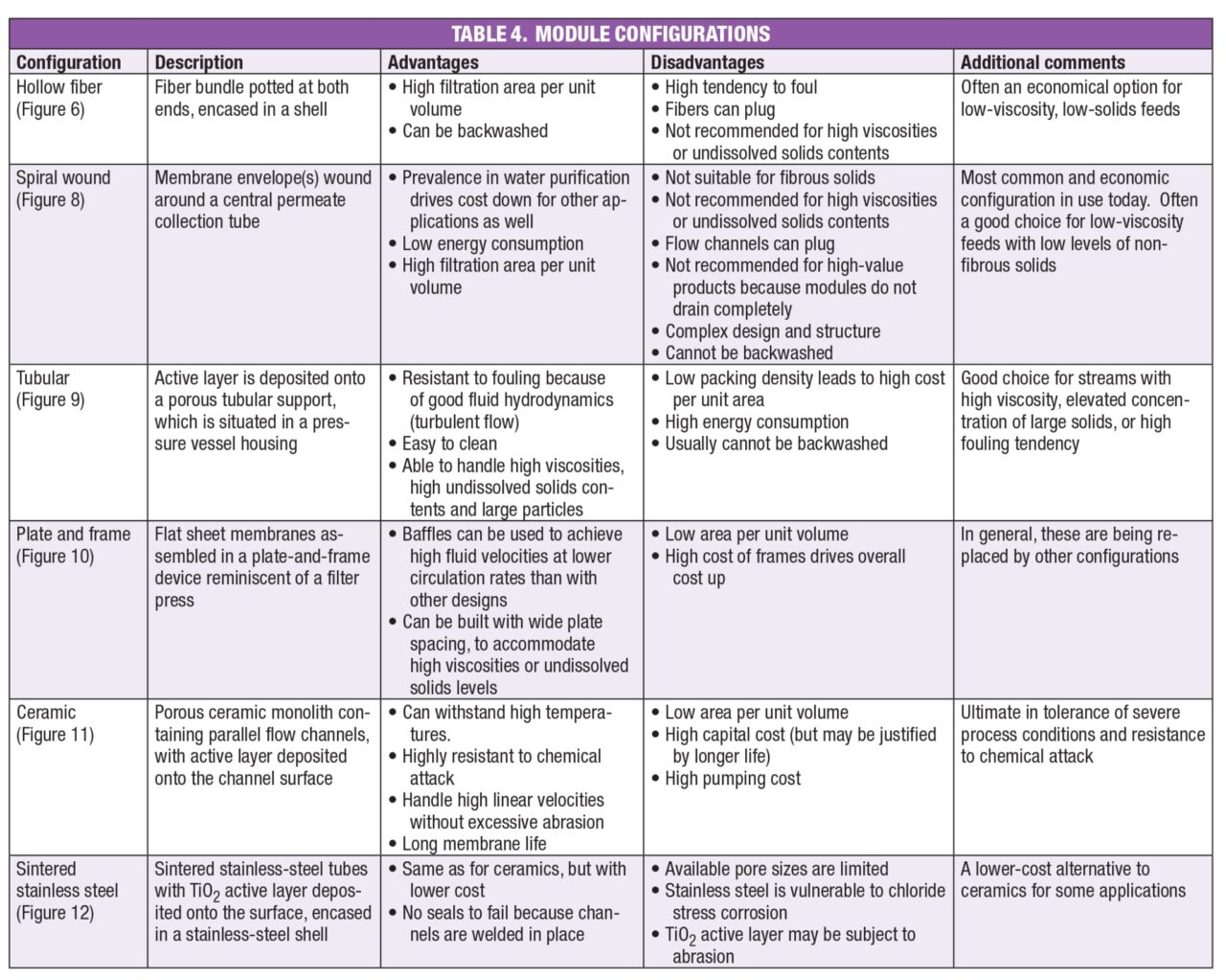
Available module configurations are described in the following paragraphs, and a summary is presented in Table 4.
Hollow fiber.This module contains a bundle of polymeric tubes, also called hollow fibers, potted at both ends and encased in a shell. The geometry is analogous to that of a shell-and-tube heat exchanger, and the tube wall is the membrane. Feed enters the tubes at the bottom, retentate leaves at the top, and permeate passes through the tube walls, then exits through the shellside. Fibers are available in diameters of 0.25–6 mm, but 1–3 mm fibers are most common. A typical module is 10–20 cm in diameter by 1–1.6 m in length. The single fiber cutaway in Figure 6a clearly shows the asymmetric nature of the pores in the tube wall. The module shown in Figure 6b contains polysulfone fibers encased in a shell that is also polysulfone, and a commercial unit using these modules is depicted in Figure 6c.
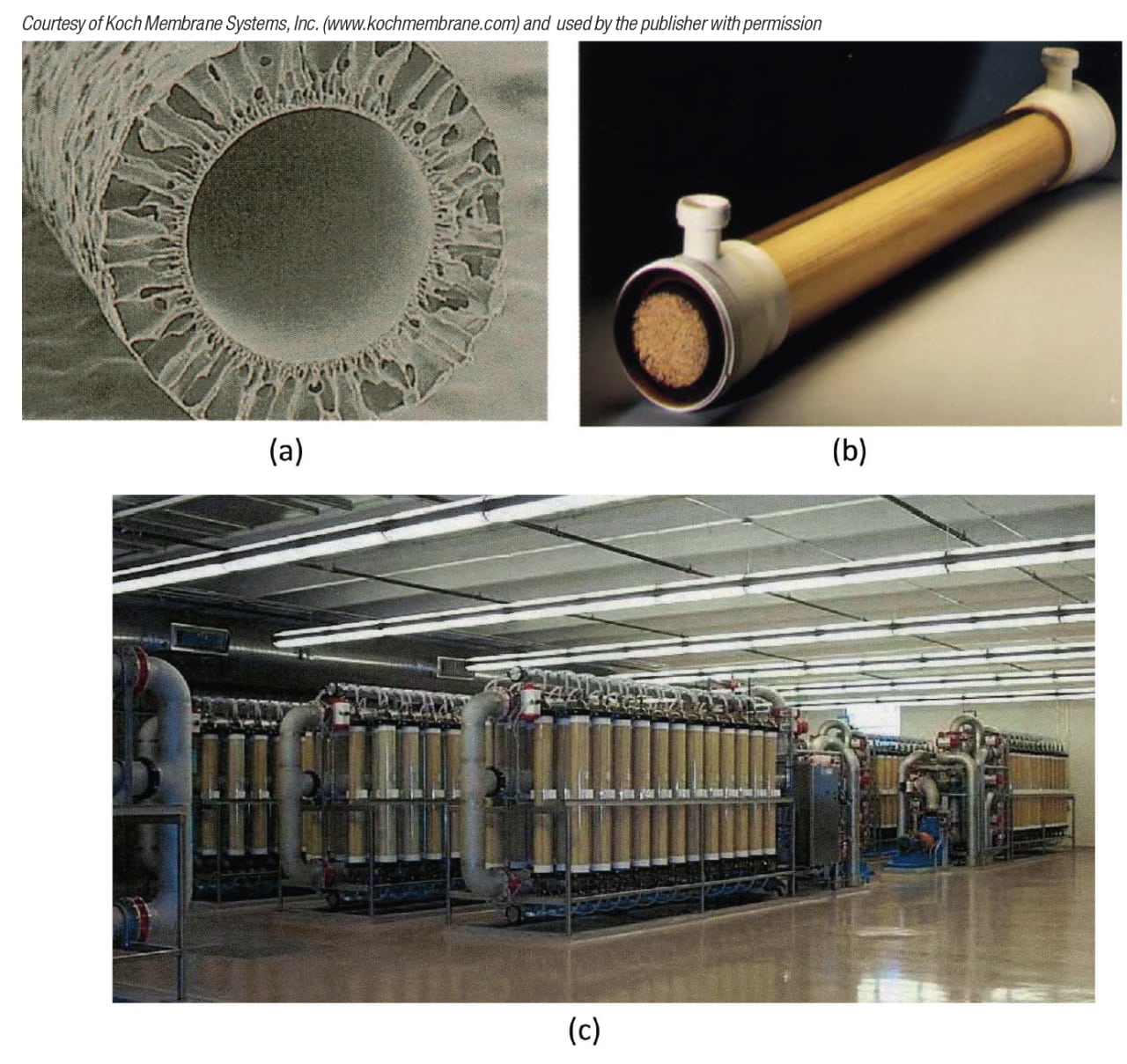
FIGURE 6. The hollow-fiber membrane configuration is shown as follows: (a): fiber cutaway showing asymmetric pore structure; (b): module containing polysulfone fibers encased in a shell that is also polysulfone; (c) commercial unit using the modules shown in (b)
The main advantage of the hollow-fiber configuration is the ability to tightly pack the fibers, allowing a high membrane area per unit volume, as high as 16,000 m 2 /m 3. Another advantage is the ability to backwash for more effective cleaning. Backwash, shown schematically in Figure 7, entails forcing water through the membrane in the direction opposite to normal flow (that is, from the permeate to the feed/retentate side), to dislodge foulants from the membrane surface. These advantages make the hollow-fiber design an economical option for many applications, especially in the food and pharmaceutical industries. For example, hollow fibers are used in over 90% of the 1,500 wine filtration plants throughout the world.
A disadvantage of hollow-fiber modules is their greater fouling tendency compared to other module configurations. In addition, fiber pluggage can occur if large solids are present, a problem that can sometimes be resolved by prefiltration of the feed. If a larger fiber diameter must be used, there is a penalty in membrane area per unit volume. Finally, hollow fibers are not suitable for streams with high viscosity or undissolved solids content. Those applications are a better fit for a tubular module, discussed below.
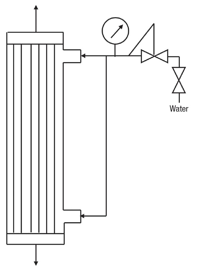
Figure 7. The ability to backwash hollow-fiber membrane modules provides more effective cleaning
Spiral wound. As shown in Figure 8, this design consists of one or (usually) more membrane envelopes wound around a perforated central core. Each envelope contains two rectangular membrane sheets facing away from each other, separated by a porous spacer. These spaces provide a path for the permeate, which flows around the spiral to the central core, then exits the module. The spaces between adjacent envelopes, separated by grids, serve as flow channels for the feed/retentate. Each envelope is sealed with adhesive on three sides, and the fourth side is attached to the central tube. Typical channel width, module diameter and length are 0.25–0.5 mm, 10–40 cm and 1–1.5 m, respectively.
Spiral-wound modules are commonly used for water purification, and the high volume drives the cost down for other applications as well. Additional advantages are lower energy consumption compared to other designs, and like hollow-fiber modules, high area per unit volume. On the downside, spiral-wound units are not suitable if fibrous solids are present, because these will clog the grids. Prefiltration is recommended to remove particles larger than one twentieth of the channel width (1/20 rule). Moreover, as with hollow-fiber modules, process streams with high viscosity or high undissolved solids content are better suited for tubular modules. Because spiral-wound modules are difficult to drain completely, the hollow-fiber design is preferred for valuable products. Finally, the design and structure of spiral-wound modules are complex, and they cannot be backwashed.
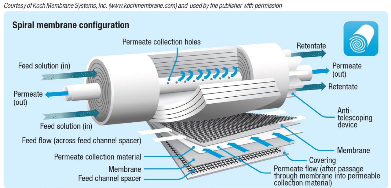
Figure 8. Spiral-wound modules are commonly used for water filtration
Despite these disadvantages, the spiral-wound module is the most common configuration in use today. It is the most economical choice for many applications, particularly water purification, as mentioned previously.
Tubular. Like the hollow-fiber design, tubular modules have a shell-and-tube geometry, but the tubes are larger, with the inner diameter ranging from 2.5 to 25 mm. The tubes consist of a porous support, such as fiberglass-reinforced epoxy, with the active layer formed on the inside surface. The shell is made from stainless steel or a hard polymer. A single module and an industrial unit are shown in Figure 9.
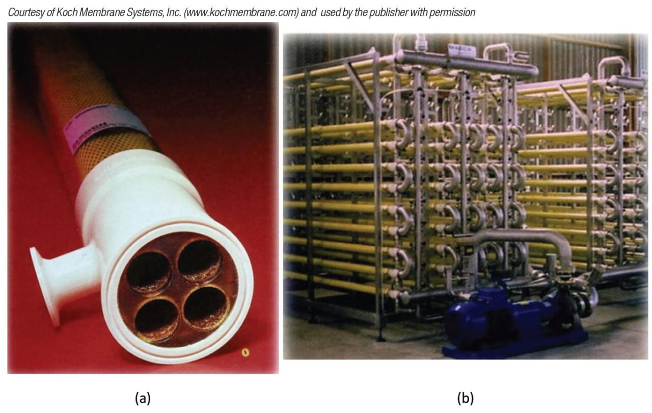
Figure 9. Tubular modules employ a shell-and-tube design, as shown in (a), a module containing PVDF tubes and a polysulfone shell; (b) shows a commercial unit using the modules shown in (a)
Tubular modules are chosen for feeds that are difficult to handle, and are not suitable for hollow fiber or spiral wound designs. These include feeds with high viscosity, high undissolved solids content, large particles (up to 2.5 mm; prefiltration: 1/10), or highly compressible or gelatinous solids. Advantages — in addition to the ability to handle these challenging streams — are high resistance to fouling, attributable to good fluid dynamics (turbulent flow); ease of cleaning; and simple module design and structure. Disadvantages are low packing density, and in turn, low area per unit volume; high energy consumption; and the inability to backwash. Applications of tubular modules include wastewater treatment, paint recovery and juice clarification.
Plate-and-frame modules. This is one of the earliest designs. These modules contain a series of flat membrane sheets, usually disk-shaped, arranged in a plate-and-frame assembly. As shown in Figure 10a, the membrane side of each sheet faces a feed channel, with the space between the opposite sides providing a flow path for permeate. This assembly, reminiscent of a traditional filter press, is situated between two end plates, with gaskets placed as needed to direct flow. A commercial unit is shown in Figure 10b.
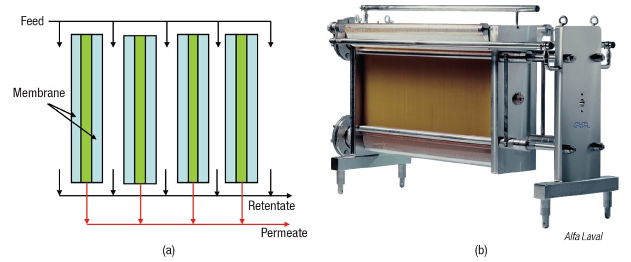
Figure 10. A plate-and-frame membrane module is shown schematically (a); and as an
industrial unit (b)
Feed channels can be narrow, for non-viscous, low-solids feeds, or wide, to accommodate more difficult process materials. In addition, baffles can be used to reach high velocities at low pumping rates. On the downside, the low area per unit volume and high cost of frames have led to a decline in the popularity of plate-and-frame modules.
Ceramics. A ceramic module consists of a porous ceramic material, called a monolith, through which parallel flow channels have been formed. The separation is performed by a thin active layer of smaller particles deposited onto the inside surface of the channels. Channel diameters are 2–6 mm, and pore sizes extend from 40 Å (NMWC = ~1,000) to the μm range. The active layer is usually α-alumina, zirconia or titanium dioxide, while the monolith is typically α-alumina or other metal oxide.
Examples of ceramic modules are shown in Figure 11. As with hollowfiber and tubular designs, a shell-and-tube geometry is used. The cylindrical inserts in the photograph are known as elements; a common design is 19 channels per element. In operation, permeate coming through the active layer flows by gravity to the bottom of each monolith, then into the shell space and out the exit port. Meanwhile, feed/retentate transverses the length of the channel, then leaves.
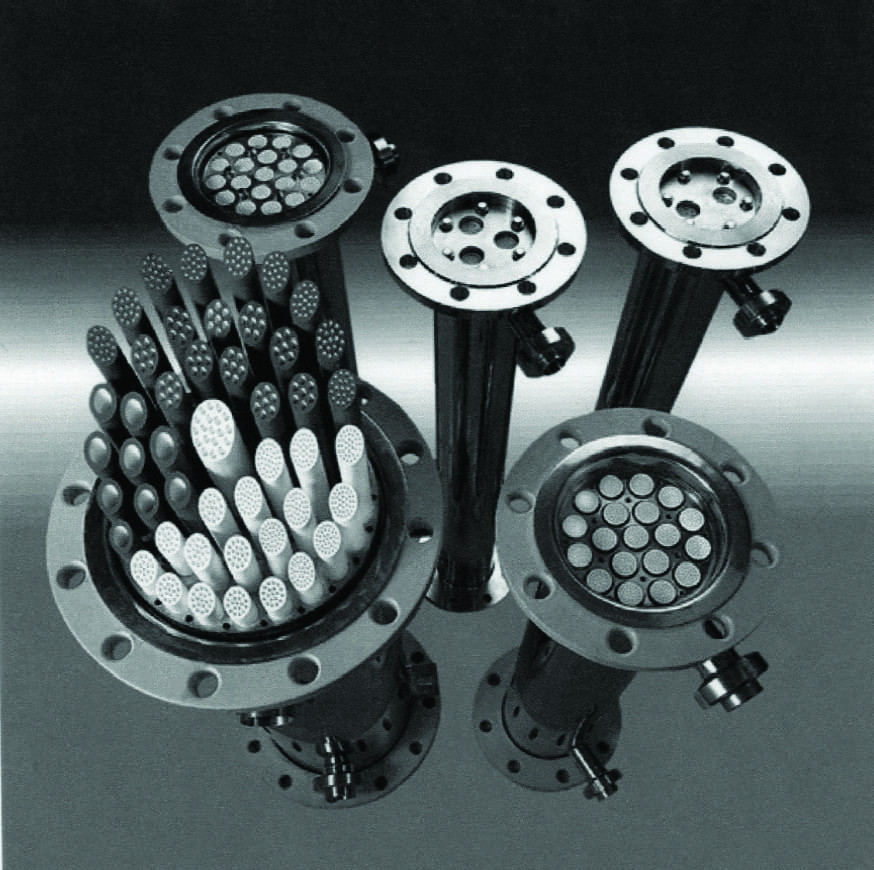
Figure 11. Ceramic modules such as these can withstand higher temperatures and more aggressive chemicals than polymeric modules
Ceramic modules can withstand temperatures of 150°C or more, much higher than the maximum of 50–55°C for many polymers. This is useful for viscous feeds, and allows high-temperature cleaning in heavily fouling applications. Moreover, ceramics are highly resistant to chemical attack, permitting their use with process streams that attack polymers. An example is the use of ceramic modules to remove wax from citrus oils, which are highly corrosive to most polymeric membranes [ 5]. Their chemical resistance also allows ceramics to be aggressively cleaned with strong acids, bases or other harsh chemicals.
Another advantage of ceramic modules is the ability to back-pulse, also called blowback. With this technique, a periodic pulse of permeate is delivered in the direction opposite to normal flow — that is, from the permeate to the feed/retentate side. This improves flux by dislodging foulants from the membrane surface. The concept is like backwashing, discussed earlier, but backwashing uses an extended flow of water during cleaning, while back-pulsing involves periodic pulses of permeate that are delivered while running product. Pulse frequency and duration vary, but typical settings are once every 2–5 min for 0.5 s.
Additional advantages of ceramic modules are higher abrasion resistance than polymers, allowing operation at a higher linear velocity; and membrane life up to 10 years, compared to 1 to 2 years for a typical polymeric membrane. The main disadvantage of ceramics is their high cost, although this is sometimes economically justified by their longer life. Other disadvantages are low area per unit volume, part of the reason for the high cost; and high pumping cost, a downside of operating at a higher linear velocity.
Sintered stainless steel.These modules are made by placing powdered stainless steel in a mold, then heating to a temperature just below the melting point. Atoms diffuse across particle boundaries, fusing the particles together to create one solid, highly porous piece. As shown in Figure 12, again, a shell-and-tube geometry is employed. The active layer is titanium dioxide (TiO2), which is annealed onto the inside surface of the channels. These modules offer most of the same advantages as ceramics, including high temperature tolerance and resistance to chemical attack, but at a lower cost. In addition, there are no seals to fail, because all connections are welded. On the downside, available pore sizes are limited with stainless-steel modules, stainless steel is subject to chloride stress corrosion, and erosion of the TiO 2 active layer can occur insome applications.
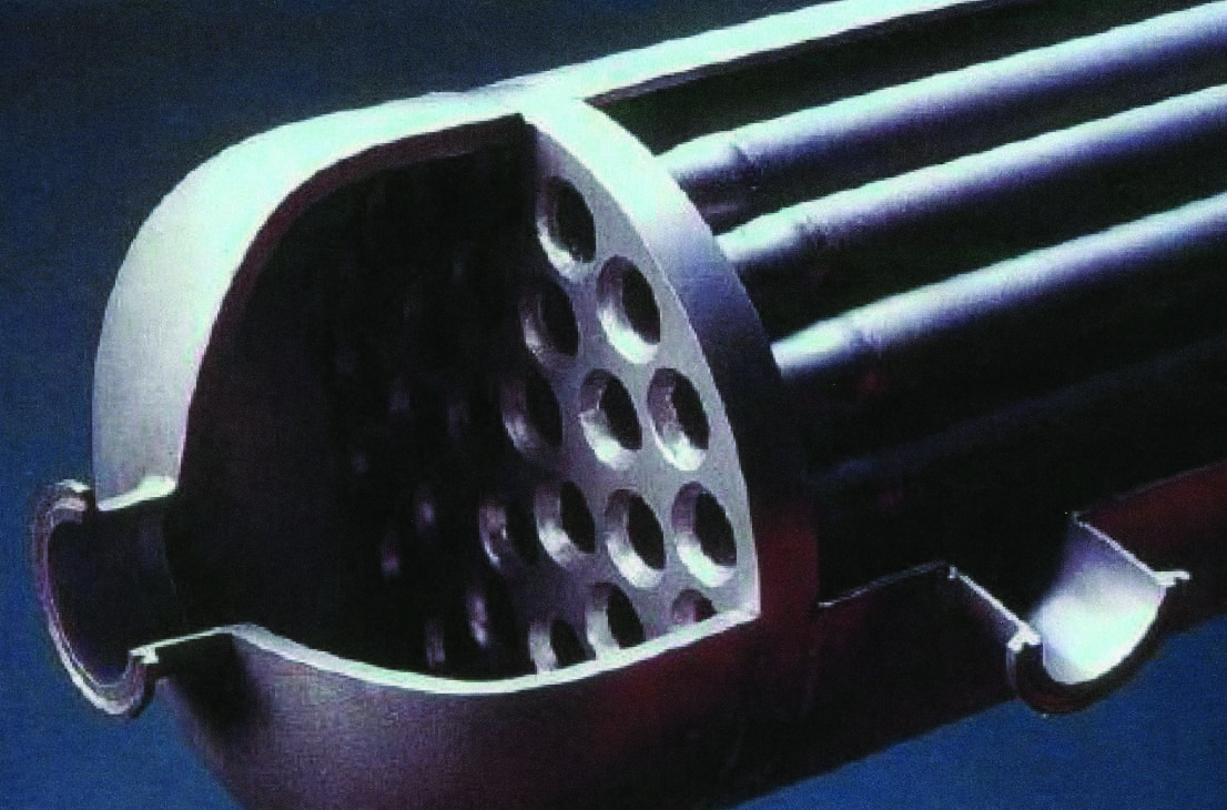
Figure 12. A sintered stainless-steel module is fabricated as one solid, highly porous unit
Diafiltration
As mentioned above, diafiltration is used to recover additional permeable components from the retentate, when the permeate is the valuable stream. Alternatively, when the retentate is valuable, diafiltration serves to improve purity by removing permeable contaminants. In a batch process (such as in Figure 2), diafiltration water is added at the same rate that permeate is removed, so that the rententate volume remains constant. It is easy to show that the displacement of permeable components obeys the exponential relationship given in Equation (3):
C( t)/ C 0 = e – Wt ⁄ V = e – N (3)
Here, C( t) is the concentration of the permeable component(s) at time t, C 0 is the concentration at the start of diafiltration, W is the flowrate of diafiltration water (equal to the permeate flowrate), V is the volume of retentate and N or Wt/V is the number of volume turnovers — that is, the volumes of diafiltration water per volume of retentate. For example, if the retentate volume is 1,000 L, each 1,000 L of diafiltration water added is one turnover. The data in Figure 13 are for removal of a residual crosslinking agent from a slurry of polymer beads. As predicted by Equation (3), 95% of the solute was removed after three turnovers.
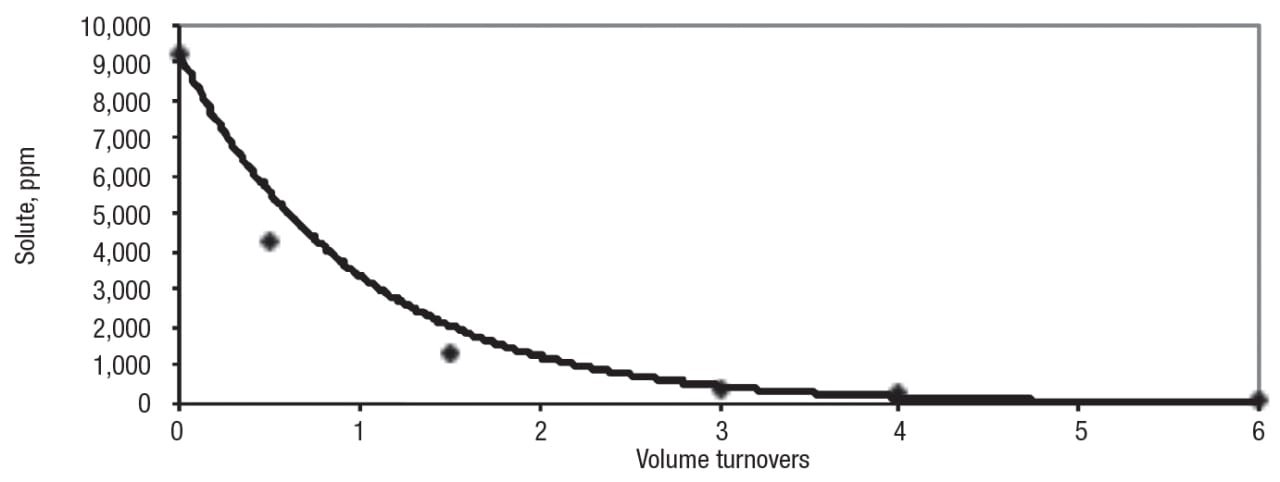
Figure 13. In this example, diafiltration is used for the removal of residual crosslinking agent from a slurry of polymer beads. The points are the actual data and the solid line is the prediction from Equation (3)
When the permeate is the valuable stream, in most cases, the water added during diafiltration must be removed downstream, usually by evaporation. The optimum amount of diafiltration water represents a trade-off between the value of the recovered product and the cost of energy.
Continuous operation
Batch and semi-continuous processing are discussed above, and these operating modes are important when volumes are relatively small. However, as with other chemical engineering unit operations, continuous processing is more efficient and cost-effective when volumes are large. In most cases, continuous membrane filtration processes contain multiple stages. This is advantageous because, for many applications, flux declines with increasing concentration of the retained species. Since each stage operates at the flux corresponding to the concentration of the retentate leaving that stage, the overall flux is higher with multiple stages, and less membrane area is needed to reach the targeted productivity. A continuous membrane system with an infinite number of stages requires the same filtration area as a batch unit. However, addition of stages eventually results in a diminishing return, because the cost of the additional circulation pump, piping, controls and other components exceeds the savings obtained from the reduced filtration area. In general, the area needed for five stages is within 20% of the batch area.
The continuous membrane filtration process shown in Figure 14 has three stages, with diafiltration water added to the third stage. With the control strategy employed, the feedrate is set independently, while the flowrate of final retentate is modulated by ratio control to maintain the desired volume reduction. Ratio control is also used to regulate the flow of diafiltration water, based on the retentate flowrate. Each stage has provisions for temperature control by heating or cooling, retentate back-pressure control and, to protect the module, a high-pressure switch that shuts off the circulation pump when activated. The circulation pumps are large, and the feedrate to each stage is only a small fraction of the circulation rate. Note that there are no controls regulating the flow of retentate from one stage to the next. These are not necessary because the system is self-adjusting and stable.
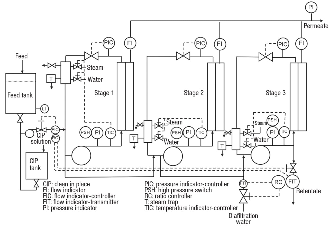
Figure 14. This example of a flowsheet for a three-stage, continuous crossflow membrane filtration process includes diafiltration added to the third stage
Membrane fouling and cleaning
Because cleaning time is non-productive, productivity is maximized when cleaning is infrequent, fast and effective. To minimize the rate of fouling and specify an effective cleaning protocol, fouling mechanisms must be well understood. Fouling may be organic, inorganic or microbiological in nature. Usually, the foulants are present as physical buildup on the membrane surface, but they may also be adsorbed, or small particulate matter may penetrate the pores. Chemical reactions on the surface may also contribute to fouling.
There are a number of strategies for minimizing the rate and extent of fouling. Prefiltration to remove large particulate matter, using a conventional filter or centrifuge, is sometimes helpful. Similarly, fouling can sometimes be reduced by upstream removal of large molecules with a tendency to foul, using a UF membrane with a relatively high NMWC. Upstream dilution of feed can reduce the rate of fouling, with the downside that a larger volume needs to be filtered. Judicious selection of the membrane material is crucial to minimize interactions with the process stream that may lead to fouling. In some cases, such interactions can be reduced by changing processing conditions — for example, temperature or pH. Finally, a high linear velocity is needed to impart sufficient shear at the membrane surface.
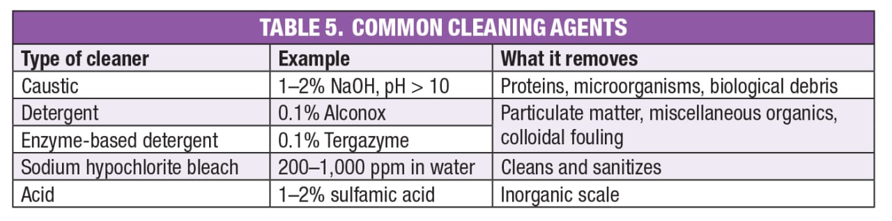
Common cleaning agents are listed in Table 5. Typically, the cleaning protocol calls for several such cleaners in sequence. For example, the following steps may be used to clean a membrane handling a stream containing microorganisms and proteins, such as a fermentation broth:
- Water rinse
- Detergent or caustic cleaning
- Water rinse
- Acid cleaning
- Water rinse
A cleaning cycle such as this one may require 3 to 4 hours. Except when using acids, cleaning is usually more effective at elevated temperature. Acid cleaning is done at room temperature because the inorganic scale it is intended to remove (for example, calcium salts) often exhibits inverse temperature solubility.
Edited by Mary Page Bailey
References
1. Gabelman, A., An Overview of Filtration, Chem. Eng., November 2015, pp. 50–58.
2. Gabelman, A., Beyond Gravity: Centrifugal Separations in CPI Operations, Chem. Eng., July 2016, pp. 52–59.
3. Zydney, A.L., Colton, C.K., A Concentration Polarization Model for the Filtrate Flux in Cross-flow Microfiltration of Particulate Suspensions, Chem. Eng. Comm. 47 (1986) 1-21.
4. Singh, N., Cheryan, M., Process Design and Economic Analysis of a Ceramic Membrane System for Microfiltration of Corn Starch Hydrolysate, J. Food Engr. 38 (1998) 57–67.
5. Finn, A., Gabelman, A., Dewaxing, U.S. Patent 9,422,506, 2016.
Author
 Alan Gabelman is president of Gabelman Process Solutions, LLC (6548 Meadowbrook Court, West Chester, OH 45069; Phone: 513-919-6797; Email: alan.gabelman@gabelmanps.com; Website: www.gabelmanps.com), offering consulting services in process engineering. Gabelman’s 39 years of experience include numerous separation processes and other engineering unit operations, equipment selection, sizing and design, process simulation, P&ID development, and process economics. He holds B.S., M.Ch.E. and Ph.D. degrees in chemical engineering from Cornell University, the University of Delaware and the University of Cincinnati, respectively. He is a licensed Professional Engineer, as well as an adjunct instructor in chemical engineering at the University of Cincinnati. Gabelman has edited a book on bioprocess flavor production, and he has authored several technical articles and a book chapter.