While chemical engineers are well-versed in designing plant piping and long-distance pipelines, the design of raw-water pumping systems is often overlooked, because civil engineers are normally commissioned to design such systems. However, it is important for chemical engineers to understand raw-water systems thoroughly, especially when considering raw-water pumping systems in hilly terrains, where there is much risk at stake when designs do not meet practical process requirements.
Any chemical process requires water for its operations. Raw water is often brought into processes from water bodies like rivers or canals using pumps and raw-water pipelines. Raw water is often fed to a softening process or demineralized for feeding to boilers to produce steam. This water may also be required as cooling water for heat exchangers to reduce the temperature and condense process vapors.
The wide range of possible ultimate uses for raw water in plants means that chemical engineers should understand the design of raw-water pumping systems, which are typically comprised of an intake well, the main pumps and pipeline components, as well as receiving tanks at the facility’s water-treatment plant. A good place to start is understanding the below considerations:
- Carefully study the area that has been identified as the source of raw water, including taking ground-level measurements and looking at other surface features
- Conduct a detailed study of the pipeline route that has been proposed to carry water from the source to the user facility, including taking ground-level measurements at 5-m intervals
- Study the proposed location of the intake-well structure (Figure 1), including the type and size that will be suitable for meeting the required quantity of raw water
- Decide on the number and size of pumps, according to the requirements and the size of pump house
- Analyze the quality of the raw water available at the source to decide on the type of water-treatment processes, if any, will be required
- Consider the method of laying the pipe, including the accessories that will be required along the pipeline route
- Check on the electrical power availability at the intake-well location, and for the pumping scheme in total
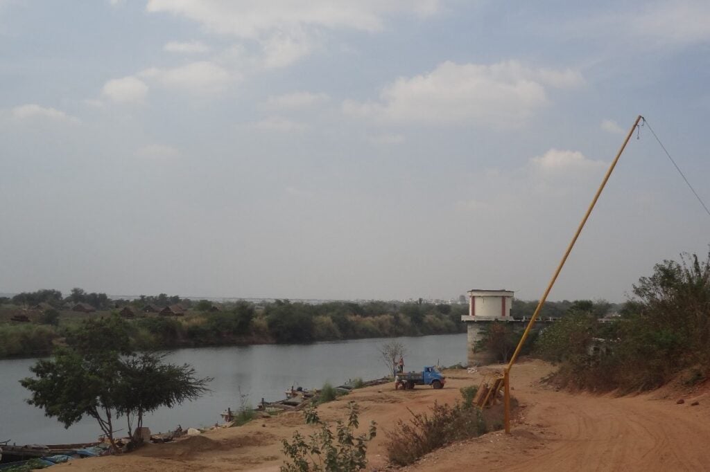
FIGURE 1. Considering the location of the intake well at the primary water source is one of the first steps in designing a raw-water pumping system
Route survey
The route of the pipeline must be decided after conducting the route survey of the entire stretch, from the intake-well position up to the proposed water-treatment plant. Valve chambers along the pipe route are suggested for the air valves and scour valves that are specified for the system.
Setting the raw-water capacity
The water capacity requirement of the facility at full commissioning stage should be calculated, along with the identification of a reliable source of raw water, whether it be from a local river, lake or elsewhere. The source of water has to be perennial and dependable. The total water requirement of the user facility is to be estimated at both the initial design phase and during commissioning to ensure a continuous supply of water is available exclusively for the required duration.
Analysis of raw water
The raw water available at the source should be analyzed for its chemical and physical properties to decide the type of treatment required. If analysis does not show the presence of harmful chemicals, extremely high salinity or pesticide contamination, only chlorination treatment may be required before distribution to the process. The water sample may need to be tested again seasonally (for instance during times of extreme rain) to check the changing characteristics of the raw water. Water samples should be tested at a reliable quality-control laboratory. After analyzing the advantages and disadvantages of the identified water source, it should also be confirmed that the location is not disturbed by higher salinity during summer, when evaporation rates rise.
River intake pump
Designers must consider the land required at the proposed intake-well location and make sure that it is suitable for the construction of an intake well made of reinforced cement concrete (RCC), which extends into the river or other water body (Figure 2), and a RCC pump house to accommodate the required pumps, along with standby pumps in the initial stages. There should also be a provision for providing one additional pump to cater to an increased water requirement after full commissioning of the facility.
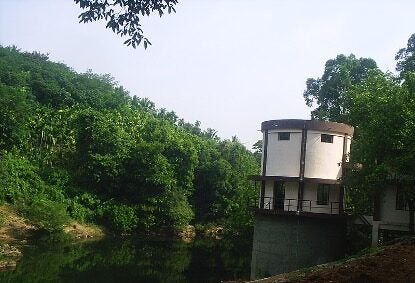
FIGURE 2. The intake well extends into the water source and should be constructed of robust materials, such as RCC
The intake-well site static head difference compared to the proposed water-treatment plant location plays a major role in the design process.
Since the source of water is likely somewhat far away from the chemical facility, water from the source is typically conveyed to the user facility through underground pipelines and directly fed into the water treatment plant. The pipeline from the intake well to the facility can typically be routed alongside existing roads in the area.
Quantity of raw water at source
Often, hydrology departments operated by local governments maintain the flow through the water body. Also, these government organizations usually maintain the amount of local water allocated for agriculture, industrial, irrigation and drinking purposes. The source of water identified should be perennial, with a reasonably good flow of water even during the summer season. Water flow through the river or canal should be continuous throughout the year and a sufficient quantity of water should be available throughout the year so that it can be continually extracted.
Materials of construction
The two prominent materials of construction used for raw-water pumping piping are carbon steel (CS) and ductile iron (DI). Pipes are laid underground, about 1.0 m below existing ground level, alongside the road leading up to the proposed water treatment plant site.
Recently, polypropylene (PP) and fiberglass-reinforced plastic (FRP) pipelines are also used in situations where the flow in the pipes is gravity-based. DI pipes are used in low-pressure applications and CS pipes are installed in higher-pressure service.
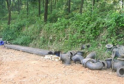
FIGURE 3. Cast iron pipes and accessories are often used in raw-water pumping systems
Fabrication cost
The fabrication cost of DI pipes per kilometer length is high when compared to CS. However, DI pipes are more durable and can provide lifetimes up to 80 years. CS pipes have a lifespan of about 25 years. Therefore, engineers must consider a tradeoff between DI and CS as materials of construction for pipes. Regardless of pipe material, the raw-water pipeline must be internally and externally cement-lined in order to withstand internal and external corrosion.
Booster pump requirements
As the optimum diameter of the pipeline dictates the discharge head of the pump, sometimes it is better to install a booster pump at the optimum location to reduce the pumping main pressures to acceptable levels. This can help reduce the intensity of accidents in the case of a pipeline rupture or leak. This is true especially when the carbon steel pipes are selected and the pressures are high.
Pumps
When determining the number of pumps required for raw-water service, engineers should consider the required capacity and head, with one standby pump available, to handle the ultimate water demand. Engineers should perform detailed design calculations for all pumps. If the static head between the intake well and the water-treatment location is high, and considering the frictional losses in the pumping mains, multi-stage vertical-turbine pumps are usually suggested for this service.
Pump house
A pump house to accommodate proposed pumps (and considering future expansion) should be designed with RCC roof and steel doors, windows and ventilators.
Pipe diameter
Finding out the most economic pipe diameter for raw-water pumping systems is a primary step in designing a successful system. The optimal pipe diameter depends on fluid velocity (typically between 0.7 and 2 m/s), pressure drop, pipeline rating, the hydraulic profile of the terrain and energy and pump costs.
Pipeline layout
The proposed pipeline for the transportation of water to the user facility will be laid underground with sufficient cover. Generally, an earth cushion of 1 m above the pipe crown is suggested for pipelines, in general, with a cushion of 1.25 m required at road crossings. It is also suggested that RCC pipes can be specified for road-crossing areas. Several technical factors affect the final choice of pipe material, such as internal pressure, coefficient of roughness, hydraulic and operating conditions, maximum permissible diameter, internal and external corrosion problems, laying and jointing, type of soil and so on. Detailed calculation of the head and pressure available for the full route should be performed. If the pumping pressure is increased due to the static head difference, it is recommended to specify CS pipeline that is coated inside and outside with 12.5-mm cement-mortar lining and with welded joints to withstand the pressure. This also simplifies any possible future repairs. The pipeline laid in the initial stretch of the system is treated as the high-pressure section. The balance length of the pipeline can be specified with ductile iron pipes with cement lining (up to the water-treatment plant area), and can be treated as the low-pressure section. Necessary valve chambers and inspection chambers must be constructed along the pipeline route. The laying of pipeline should follow procedures given in typical industry standards and codes. The width of the trench is designed to provide no less than 200 mm clearance on either side of the pipe. Additional width should be provided at joints for proper welding the joints with the required size of welding pits. After it is laid, the pipe line will be secured in place with approved backfill materials tamped under it, except at the joints.
Surge analysis
Surge analysis of the pipeline is to be conducted for the safety of the line. The details of the analysis and the surge protection recommendations should be incorporated into the final design of pipeline.
Developing the total system cost estimate
The total estimated cost for the system should include the intake well, pump houses, pumping main, pipeline, motors, transformers and electrical works, and exclude the cost of water treatment.
Pipeline testing
After laying and jointing, the pipeline must be hydro-pressure tested to ensure that pipes and joints are sound enough to withstand the maximum pressure likely to be developed under working conditions.
Valves
A common non-return valve, gate valve and scour valve are usually specified immediately downstream of the pump house, in addition to the individual sluice valves and non-return valves dedicated for each pump. The location of the air valve along the pipeline route is specified at the peak elevated points of the pipeline. The suggested location of all valves are to be identified during the design phase. Also, all pump discharges are connected to a common header.
Valve chamber
Water-tight valve chambers of suitable size should be constructed at specified locations along the pipeline, and the chambers should be made of reinforced concrete, with manholes on top with cast iron covers.
Overhead tanks and treatment
The water treatment plant will likely contain overhead tanks, including for aeration, sedimentation, filtration and chlorination. The water treatment plant area should include a freshwater tank and overhead tanks, and these should be considered in the overall design of the raw water system.
While treatment costs are not included in the total cost estimate, the supply and erection of a pressure-sand filter with a necessary dosing system should be considered in the cost estimate. ♦ Edited by Mary Page Bailey
Acknowledgement
All images provided by author
Author
 Koya Venkata Reddy is currently the deputy general manager, Process, at FACT Engineering and Design Organization in Kochi, India (FEDO; Email: koyareddy@factltd.com). He holds an M.B.A. in finance from Indira Gandhi National Open University (IGNOU) in New Delhi and an M.S. in project management from Cochin University of Science and Technology (CUSAT) in Kochi. He joined FACT in 1991 and has over three decades of experience in the areas of plant operations, troubleshooting, optimization, process design, chemical plant revamps, process simulations, energy audits and so on. Reddy is a long-term member of the Indian Institute of Chemical Engineers (IIChE), FACT Technical Society and is active in many other industry organizations. He is also currently a faculty member at the FACT Training Center for Safety Audits.