The importance of heat-exchanger orientation on process operations is illustrated using a real-world case study from an ethylene oxide/ethylene glycol plant
The flow dynamics associated with the presence of both a liquid and a gas (or vapor) phase inside a flow channel are complicated. Several physical factors are involved, including the total flowrate, the phase velocities and the interface characteristics.
For two-phase heat-transfer and pressure-drop correlations to be accurate, the flow regime effects must be taken into consideration. The different flow patterns (for instance, annular flow or stratified flow) can be grouped into two major regimes — gravity-controlled and shear-controlled flow. When considering the flow within a heat exchanger, geometry and orientation typically determine the regime and pattern. In particular, the difference between the gravity- and shear-controlled regimes is most evident in horizontal flow configurations (Figure 1).
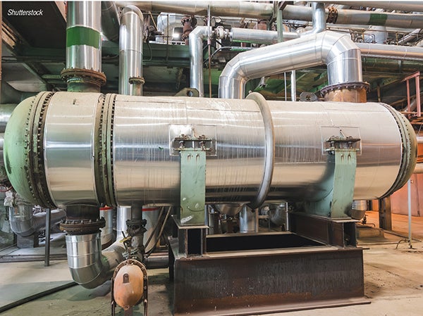
FIGURE 1. When considering heat-exchanger flow, geometry and orientation determine the regime and pattern. This distinction is most apparent in horizontal configurations, where the gravity- and shear-controlled regimes differ most clearly. This picture depicts a generic horizontal shell-and-tube heat exchanger
Considering the parameters related to these flow regimes, exchanger orientation becomes a critical aspect for guaranteeing effective and efficient heat transfer. This article outlines these concepts using a real-world case study.
Case study: EO/EG plant
In ethylene oxide/ethylene glycol (EO/EG) plants, EO-rich water, which contains EO and other dissolved gases (such as ethylene, CO₂ and methane), is heated in the feed-bottom exchangers by interchanging heat with EO-lean water before feeding to the stripping column.
In one of the plants, existing feed-bottom exchangers were replaced with horizontal, hybrid-type exchangers during a period when the plant was undergoing turnaround and debottlenecking (DBN). In hybrid exchangers, the flow channels are created by a system of welded plates. The intent of the replacement of these exchangers at the plant was to reduce the temperature approach from 10–12°C (pre-DBN) to 5°C; and to increase the temperature of the EO-rich water feed to the EO stripping column by 10°C. This would reduce the low-pressure (LP) steam consumption in the column by around 30–35 metric tons per hour (m.t./h).
In the hybrid heat exchangers, the EO-rich water was passed through the tube side of the exchanger while the lean water was passed through the corrugated side of the plate pack. However, after startup, inadequate heat exchange in the new feed-bottom exchangers was reported, with an increase in the temperature approach compared to pre-DBN and a lower heat-transfer coefficient (HTC) than the design value. This resulted in very high steam demand in the EO stripping column due to a lower rich-water temperature going to the column, which created a significant impact on the energy intensity of the plant.
The vendor of the unit evaluated the poor performance, and various measures were suggested and implemented to recover the duty of the feed-bottom exchangers. These measures included pressure-drop measurements across all the four heat exchangers (connected in parallel), and the addition of several venting connections from the rich-water process side, to try to remove the gas that was suspected to be trapped inside the heat exchanger. However, the performance of the exchangers could not be restored.
Methodology and approach
A fundamental study was carried out to assess the underperformance of the exchangers, with the following steps:
- Calculate the amount of vapor (by volume) present in the rich-water feed
- Calculate the velocity on the rich-water side to check the flow regime of the two-phase flow
- Model the exchanger according to first principles, in both the horizontal and vertical configuration
Analysis and findings
The rich flow is two-phase due to the presence of 8–15% vapor on a volumetric basis. The rich water flows in the tube side of the hybrid exchangers. The calculated superficial velocities of the liquid and vapor phase were found to be around 1 m/s and 0.15 m/s, respectively.
The two-phase flow at low superficial velocities in a horizontal configuration causes stratified or slug/plug type flow, with separate layers of liquid and vapor and the vapor flowing in the upper section of the conduit (Figure 2).

FIGURE 2. This schematic illustrates the slug/plug flow regime in horizontal tubes
For comparison purposes, the heat transfer and flow regime within the exchanger’s channels were also modeled for two alternate configurations (horizontal and vertical). The results are shown in Table 1.
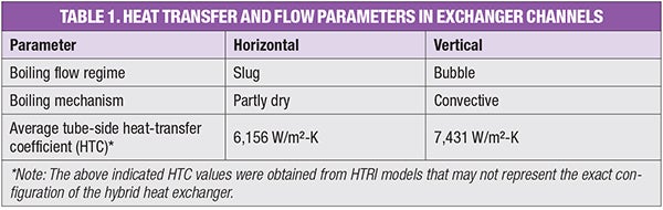
As per the above analysis, the exchanger’s horizontal orientation was found to be a major contributing cause for the underperformance of the exchanger. It is suspected that blanketing of some of the active heat-transfer surface area occurred, due to accumulation of vapors in certain areas of the heat exchanger, despite the process notes recommending a free-venting design in the context of a globally upward flow. This accumulation of gas/vapor is intended to be different than the normal coexistence of gas/vapor and liquid within the flow channel based on the respective fractions. Figure 3 depicts the effect of a gas/vapor layer on heat transfer across a metal wall in terms of additional thermal resistance.
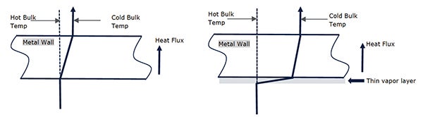
FIGURE 3. A layer of vapor between liquid and metal wall significantly impacts heat transfer
A free-venting design would prevent such undue accumulation and would be provided by a heat exchanger having a vertical, up-flow orientation.
Recommendations
The horizontal orientation of the flow channels was suspected of affecting the deterioration of heat-transfer performance in the hybrid-type cycle-water exchangers, therefore resulting in a higher temperature approach.
At the low superficial velocities and in the horizontal configuration, the flow regime of the rich water two-phase tube-side stream is at the boundary between slug, plug and stratified flow, causing the gas/vapor phase to be at the top portion of the cross-section. To exit these regimes and enter a bubble-type regime, either the velocity between plates should be increased, or the rich water should be passed through the corrugated side of the exchanger.
The exchangers were instead replaced with a new type of vertical exchanger, in which the design heat duty and performance were achieved with a reduction in steam consumption of more than 20%. This reduction was key for improving the energy intensity of the plant asset and reducing the carbon footprint, besides the operating costs.
Hence, the selection of the exchanger orientation should not be dictated only by the plot plan or space constraints. The consideration of the flow regime impact is also very critical during the design phase to achieve the required heat-transfer performance. ■
Edited by Mary Page Bailey
Acknowledgement
Figures provided by authors unless otherwise noted
References
1. Corneliussen and others, Handbook of multiphase flow metering, Norwegian Society for Oil and Gas Measurement (NFOGM), March 2005.
2. Talapatra, S., and Farrell, K., Two-Phase Flow Regimes in Exchangers and Piping: Part 1, ASME International Mechanical Engineering Congress & Exposition, Houston, November 2015.
3. HTRI Design Manual Volume-B, Exchanger Performance Prediction Methods, December 2025.
Further reading
1. Oskousian, A., Heat Exchangers, Cooler and Heaters, Chem. Eng., pp. 39–41, May 2025.
2. Buecker, B., A Brief Review of Natural Water’s Influence on Scale Formation in Heat Exchangers, Chem. Eng., pp. 40–41, February 2024.
3. Bryan, S. and Holmquist, J., Corrosion Prevention for Heating & Cooling Systems, Chem. Eng., pp. 21–24, January 2024.
Authors
 Jai Prakash Jain is a lead scientist at SABIC Technology Center, Jubail, as part of the company’s Glycols Technology & Innovation group (Email: jainjp@sabic.com; Phone: 966-535913643). He has over 15 years of experience in manufacturing and R&D with skills in process optimization and process development studies, debottlenecking and growth projects from the conceptual to commissioning phase, along with extensive experience in plant troubleshooting using various modeling and data analysis tools.
 Marco Fazzini has nearly 20 years of experience in the heat transfer sector. He has served as a subject matter expert executing thermal design and advanced analysis of heat exchangers for performance enhancement and troubleshooting. Fazzini was formerly employed at SABIC Americas LLC in Houston as a staff scientist.
 Pankaj Paghdar is a staff scientist at SABIC Technology Center, Jubail as part of the company’s Glycols Technology & Innovation group (Email: paghdarpm@sabic.com; Phone: 966-532398219). He is a manufacturing professional with over 27 years of experience in process optimization, plant troubleshooting and advanced data-driven modeling, with a strong track record in debottlenecking and capacity growth projects from concept through commissioning.
 Mohammed Al-Sekhan is a director of Science Advisory & Partnerships based at the SABIC Technology Center at Jubail (Email: sekhanma@sabic.com; Phone: 966-537736618). He has over 15 years of experience in engineering, manufacturing and R&D, and has been leading several engineering and technology groups for different products within SABIC.
 Mansour Al-Shammasi is a staff process engineer at Saudi Kayan Petrochemical company, Jubail as part of the company’s process engineering group (Email: shammasimh@saudikayan.sabic.com; Phone: 966-506880160). He has over 16 years of experience in manufacturing of basic and specialty chemicals in several technologies, as well as process safety, process design and mega-projects execution. His skills cover process optimization and troubleshooting, process development studies, FEED and detailed engineering development, process hazard analysis (PHA) studies and plant pre-commissioning and commissioning.