When considering the use of a silo discharge system to help convey materials, it is crucial to assess the specific requirements of the materials being stored, the operational goals and the overall system compatibility
Storing and handling dry bulk powders in bins and silos can lead to several different material-handling problems. These issues can impact material flow, product quality and overall process efficiency. Assuring material discharge from storage silos is crucial for many industrial processes, because it ensures a continuous and controlled flow of materials.
To address such problems, various techniques and equipment, such as mass-flow bins, bin activators, aeration systems, flow aids and vibrators can be employed to ensure reliable material flow and minimize issues associated with storing and discharging dry bulk powders from bins and silos. Careful material selection and design considerations are also essential to mitigate challenges.
This article outlines some of the equipment and technologies available to assist in material discharge, and provides guidance in selecting the most appropriate option for a particular application.
Material flow issues
Some of the common material-handling problems associated with storing dry bulk powders in silos are illustrated in Figure 1 and described in the following sections.
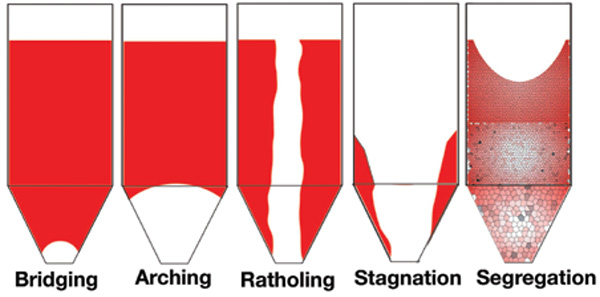
FIGURE 1. Storage of dry bulk materials in bins and silos can lead to a variety of material-flow issues that can potentially impact the product quality
Bridging. Bridging occurs when the powder forms a stable arch or crust across the top of the silo, blocking the material’s flow. This can happen due to material cohesion or if the material’s surface moisture has caused it to adhere to the walls of the silo.
Arch breakage. When attempting to dislodge a bridge or rathole by force, it may result in the sudden release of material, causing unpredictable and uncontrolled material flow, which can be dangerous and damaging to equipment.
Ratholing. Ratholing refers to the formation of a vertical channel down the center of the silo, leaving material stagnant on the sides. This is often caused by poor material-flow properties, such as when the material segregates and the finer particles flow preferentially.
Segregation. Some dry bulk powders can segregate within the silo, leading to uneven material composition. This results in inconsistent product quality when the material is discharged from the silo, and it can be problematic in industries like pharmaceuticals or food processing where material homogeneity is critical.
Material stagnation. Stagnation can occur when material becomes trapped in the corners or along the walls of the silo, reducing discharge efficiency. Material stagnation can lead to product contamination, spoilage and the need for manual intervention to clear any blockages.
Flowrate irregularities. Irregular flowrates can disrupt downstream processes and make it difficult to meet production targets. This can be caused by inconsistent flow from the silo, resulting in batching errors or process inefficiencies.
Material caking. Some dry bulk powders are prone to caking or agglomeration, especially when exposed to humidity or moisture. Caking can lead to material blockages, reduced flowability and difficulties in discharging material from the silo.
Operational downtime. Frequent material-handling issues may lead to unplanned downtime for maintenance, cleaning or clearing blockages, which reduces overall process efficiency and productivity.
Silo Flow Aids
Selecting the best option for your process from among the various methods to assure material discharge from storage bins and silos requires consideration of plant scale, material properties, energy consumption, safety requirements and so on. The following sections describe several types of flow aids for silos and bins.
Gravity flow (mass-flow bins)
Free-flowing material can often be discharged simply by relying on gravity, as demonstrated in mass-flow bins. The silo design can be optimized to achieve this gravity-flow effect. Beyond that, more complex and specific designs can be used to achieve mass flow and even discharge of material on a first-in-first-out (FIFO) basis. Mass flow is an important consideration for avoiding stagnation and segregation of material, which can upset a production line and affect the quality of the end product.
Designing mass-flow bins requires careful analysis of material properties to arrive at a bin geometry that encourages proper flow. These types of bins typically have different shapes than the common conical-bottom bins. The outlet may also have geometry other than a circular design (Figure 2). This requires consideration of overall plant design and downstream equipment to accommodate unique geometrical features.
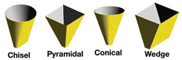
FIGURE 2. There are a number of geometry options for gravityflow bin designs, and selection of the proper shape requires consideration of downstream processing equipment and overall plant requirements
While mass-flow bins are helpful in solving several bin flow problems, they usually cannot accommodate changing material or environmental characteristics, such as from humidity or off-specification products. Furthermore, a mass-flow bin designed for one material will most likely not be usable on another material. Below are some general considerations for installing mass-flow bins.
Higher initial cost. Mass-flow bins are typically more expensive to design and construct compared to conventional bins or hoppers. The highly specialized design and flow-control mechanisms can increase the upfront investment. Because there is no mechanical agitation to wear out or break down, maintenance costs are low.
Design complexity. Designing a mass-flow bin requires a good understanding of the material properties, flow characteristics and the specific requirements of the application. Achieving the desired flow performance can be a complex engineering task. Mathematical models for design of appropriate hopper-discharge angle have been developed, making it possible to find the hopper-discharge angle required to obtain mass flow. However, achieving proper mass flow can be sensitive to variations in design parameters, material properties and operating conditions. Small deviations from the optimal design can lead to flow issues.
Space requirements. Mass flow bins often have a tapered or conical shape, which can require more space compared to other types of storage vessels. This can be a limitation in facilities with limited space available for storage.
Mass-flow bins are effective for cohesive and non-free-flowing materials. They may not be suitable for all types of materials, particularly those with very challenging flow properties or highly abrasive characteristics.
Bulk density variability. Mass-flow bins may have limitations in handling materials with highly variable bulk densities. Material level (headload) in a bin will directly affect the density of powders. These variations can affect the flow-control mechanisms (feeders) and require constant adjustments (speed) to maintain accurate flow.
Material stagnation. While mass-flow bins are designed to minimize stagnant regions, material can still occasionally become stagnant in certain conditions, leading to flow disruptions. Unfortunately, mass-flow bins are unable to be modified to improve material flow if material-handling characteristics have changed.
Despite these disadvantages, mass-flow bins remain a valuable solution for industries where maintaining reliable material flow and minimizing segregation are critical for product quality and operational efficiency. The decision to use a mass-flow bin should be based on a careful assessment of the specific material-handling requirements and a cost-benefit analysis of the investment.
Bin activators
Vibrating bin dischargers, or bin activators, are conically shaped structures that replace a portion of the lower cone of a typical bin (Figure 3). They are flexibly supported from the bin and vibrated horizontally. The vibrational forces, combined with the unit’s internal geometry and baffling, provide flow of material through a bottom outlet. Unlike gravity or mass-flow bins, bin activators can accommodate a wide range of materials and characteristics. If materials or characteristics change, the vibration force can be adjusted to accommodate.
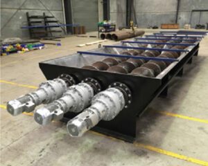
FIGURE 10. Live-bottom screw feeders are best employed in applications with large discharge openings. They employ several feed screws in tandem to prevent the formation of bridges or caverns in the material
Like mass-flow bins, bin activators promote FIFO flow. Their internal baffles encourage flow from the entire bin cross-section, while the baffling also mixes material from the center and periphery to avoid segregation (Figure 4). Bin activators are sized based on bin diameter and material handled. Bin activators offer many advantages for assuring continuous material flow from storage, described below.
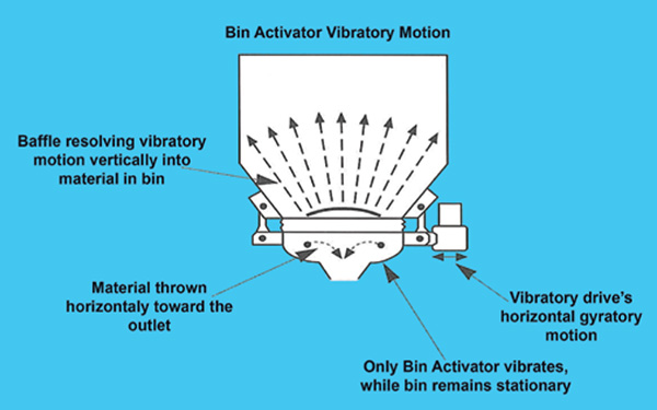
FIGURE 4. Bin activators feature internal baffling that help to avoid segregation. The device is designed so that the bin remains stationary while only the activator portion vibrates
Cost. Cost range is based on the size of the bin discharger, which is based on what type of material is being handled and the size (diameter and straight side) of the silo. The bin activator may range in size from 2 to 18 ft in diameter.
Promotes FIFO flow. FIFO flow is crucial in many industries to ensure product quality and prevent material degradation or spoilage. Bin activators facilitate FIFO flow by consistently discharging material from the bottom, ensuring that the oldest material is the first to be discharged.
Handles cohesive and viscous materials. Difficult-flowing materials, such as clay, sludge or sticky powders, can be effectively handled by bin activators.
Uniform discharge rate. By using controlled vibration, the material being handled is conditioned to a constant bulk density by removing entrained air. Bin activators provide a consistent and controlled discharge rate, which is essential for processes that require precise material feeding or dosing. This uniform flowrate enhances process efficiency and accuracy.
Reduced material segregation. Some materials tend to segregate or separate into different particle sizes during storage or handling. Bin activators can help minimize material segregation by ensuring a consistent flow of material with minimal disturbance.
Low maintenance. Bin activators are relatively low-maintenance compared to other material-handling equipment. They have few moving parts, making them not very prone to wear and tear.
Versatility. Bin activators can handle a wide range of materials, including powders, granules and slurries, making them versatile in various industries, such as agriculture, food processing, pharmaceuticals and construction. They can be easily modified in the field should the material itself or the material-handling characteristics change.
Safety. Bin activators are generally safer to operate than some other material-handling equipment because they have fewer components that are exposed to operators and fewer risks of material spillage or dust emissions.
Environmental benefits. Efficient material handling with bin activators can lead to reduced material waste, improved product quality and minimized environmental impact.
In summary, bin activators are advantageous for handling difficult-flowing materials because they ensure consistent and controlled material discharge, prevent blockages, promote FIFO flow and are versatile and relatively low-maintenance. These benefits make them a valuable tool in industries where reliable material handling is essential.
Non-material-contact vibrators
Storage silo vibrators are used to promote the flow of bulk materials within silos, hoppers and bins. They come in various types, each designed to address specific flow problems and material characteristics.
Due to their low cost compared to mass-flow bins and bin activators, storage-bin vibrators (Figure 5) are often the first choice to help with bin flow problems. They are limited, however, in the amount of vibration that can be applied, since they directly fasten to the bin structure and if sized too large, can cause cracking and other structural problems. But for material that needs a little persuasion to get moving, they can be very cost-effective.
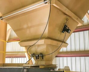
FIGURE 5. Storage-bin vibrators provide a lowcost method to help with material-flow problems, but since they are directly installed onto the bin surface, careful consideration must be taken in their specification
Vibrators generally all work with the same principle, just with differing drive mechanisms. Pneumatic vibrators use compressed air to produce linear or rotary vibrations. Device types include piston, ball, turbine and eccentric weight. The latter provides the highest force output for the toughest flow problems. Electric and hydraulic vibrators use a motor to rotate eccentric weights and are most often used for higher-vibration force applications. Electric vibrators tend to be the most energy efficient. Pneumatic and hydraulic options are less efficient due to losses associated with fluid flow.
Since they only provide external non-material contact, vibrators do not help with flow issues like segregation. They may get material moving, but it may also be segregated on discharge. The following sections list some of the most common types of storage-silo vibrators.
Pneumatic piston vibrators. These vibrators use compressed air to generate linear vibrations. They are effective for both promoting material flow and preventing material bridging or ratholing.
Pneumatic ball vibrators. Pneumatic ball vibrators use the impact of a rotating ball inside a housing to generate vibrations. They are suitable for dislodging sticky or compacted materials.
Pneumatic turbine vibrators. Turbine vibrators use high-speed airflows to create vibrations. They are often used for promoting material flow in bins and hoppers.
Pneumatic roller vibrators. Roller vibrators consist of a roller mounted on a shaft. Compressed air alternately pushes and releases the roller, creating vibrations. They are effective for materials prone to arching and bridging.
Pneumatic vibrating-piston vibrators. These vibrators combine both linear and rotational motion to promote material flow. They are suitable for challenging flow problems.
Electric vibrators. Electric vibrators are powered by electricity and typically use eccentric weights or motors to generate vibrations. They come in various designs, including rotary, linear and electromagnetic vibrators.
Hydraulic vibrators. Hydraulic vibrators use hydraulic fluid to generate vibrations. They are commonly used in applications where electricity or compressed air is not readily available.
Air-knocker vibrators. Air-knocker vibrators use short bursts of compressed air to generate shock waves within the material, helping to dislodge compacted material and promote flow.
Silo cone vibrators. Silo cone vibrators are specifically designed to be installed at the outlet cone of silos. They help prevent material blockages and ensure a consistent material flow.
The choice of vibrator type depends on various factors, including the type of material being stored, its flow properties, the size and geometry of the silo and the specific flow issues that need to be addressed. Properly selected and installed vibrators can significantly improve material discharge and prevent flow-related problems in storage silos (Figure 6). Choosing the wrong type of vibrator can exacerbate problems, sometimes making them much worse.
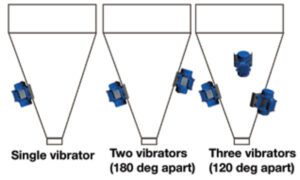
FIGURE 6. The proper geometry and arrangement of silo-bin vibrators depends on the specific flow issues that occur in the bin. However, selecting the incorrect vibrator device or installing the devices in ineffective positions could lead to worsened flow problems
Vibrator energy considerations
The energy consumption of electrical vibrators and pneumatic vibrators used for silo discharge can vary significantly depending on several factors, including the type and size of the vibrator, the frequency and duration of use and the specific application.
Vibrators typically need to transmit their energy through the structure or material they are working on. This can result in a loss of power, as some of the vibrational energy is absorbed by the structure itself. This could potentially reduce the efficiency of the vibration process.
The transmission of vibrational energy through a structure can potentially lead to the propagation of cracks or wear over time. This is a concern, especially in materials that may be sensitive to vibrational forces, such as certain types of metals.
It is also worth noting the potential for material damage with long-term vibrator use. Severe or prolonged use of vibrators can contribute to long-lasting damage to the material or structure. This is a significant consideration, especially if the material is prone to fatigue or if the structural integrity is crucial for safety.
Vibrators, depending on their intensity and frequency, can compact materials. In some cases, this compaction might restrict the movement of bulk materials.
It is important to note that the impact of vibrators can vary based on several factors, such as the type of material, the frequency and intensity of vibrations and the overall design and condition of the structure. Engineers and operators typically need to carefully assess these factors to minimize potential negative effects and optimize the use of vibrators for specific applications.
Energy source. Electrical vibrators are typically powered from the power grid. Pneumatic vibrators are powered by compressed air, which is generated using air compressors that consume power from the electrical grid. Pneumatic vibrators may be less energy-efficient compared to electrical vibrators because of energy losses in the air compression process and the conversion of compressed air into mechanical vibration.
Frequency and amplitude adjustment. Most electric vibrators provide adjustable eccentric weights that control the amount of force (amplitude) that is imparted into the bin structure. This allows the vibrator to match the required force to make the material in the silo flow. Many electrical vibrators offer some variable speed control, allowing users to adjust the vibration frequency as needed. This can help optimize energy consumption.
Power consumption. The power consumption of electrical vibrators can range from a few hundred watts to several kilowatts, depending on the size and power rating of the vibrator and the number of vibrators required for the application. The power consumption of pneumatic vibrators can vary widely based on factors such as air pressure, air volume, and the specific vibrator design. It can range from a few hundred watts to several kilowatts or more. The overall power consumption of pneumatic vibrators also depends on the efficiency of the air compressor system, which can vary.
In general, electrical vibrators tend to be more energy-efficient than pneumatic vibrators. However, it is essential to consider the complete system, including the energy required to generate and distribute compressed air in the case of pneumatic vibrators. Additionally, the choice between electrical and pneumatic vibrators may also depend on other factors, such as the availability of electrical power, the surrounding environment (for example, the presence of explosive atmospheres) and the specific requirements of the application.
To make an informed decision regarding energy consumption, it is advisable to consult with vibrator manufacturers, perform energy audits and consider the specific operating conditions and requirements of your silo discharge system.
Aeration systems
Aeration systems involve introducing compressed air into the bin or silo to fluidize the material (Figure 7). This can be particularly effective for materials that tend to compact or have high moisture content. Fluidization makes it easier for materials to flow out of the silo. Types of aeration equipment include fluidizers and silo air blasters.
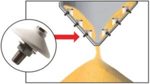
FIGURE 7. Aeration systems use streams of compressed air to help fluidize bulk materials and promote better flow
Fluidizers. Fluidizers are a pneumatic-flow aid that use a combination of aeration and gentle vibration to promote material flow. The discs force air to move along the vessel wall, which loosens the material and prevents it from plugging or becoming compact. They can be installed outside or inside the vessel and are usually made of silicone or ethylene propylene diene terpolymer (EPDM) rubber.
Fluidizers work best with dry bulk materials that respond to gentle aeration or have a moisture content that is less than 12–15%. There are models designed for either low-pressure-high-volume or high-pressure-low-volume air, but they generally have less power and a smaller activation radius than other flow aids. Fluidizers are inexpensive and easy to install, since they only require a small hole in the silo for the discs.
A downside of using fluidizers is the limited activation radius. A greater number of units may be required to achieve the desired material flow results. Frequent replacement is another concern. They degrade quickly — even slightly uneven edges on the disks can lead to inconsistent airflow or affect its ability to seal tightly against the vessel walls. In these cases, the fluidizers must be replaced.
Fluidizers may also be ineffective for some materials. Fluidizers can only activate dry powders or light solids. They cannot be used for large particles like gravel, interlocking particles like wood shavings or fiberglass, or moist or dense material like whey. Abrasive powders degrade the nozzles
It is also crucial that air from the compressor be oil- and moisture-free, and at ambient temperatures. Otherwise, material may become contaminated or altered.
Silo air blasters. Silo air blasters (also known as air cannons) are devices used to dislodge and break up material blockages and buildups in storage silos, bins, hoppers and chutes (Figure 8). They work by releasing a high-pressure burst of compressed air to shock and dislodge the stuck material.
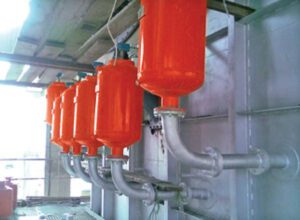
FIGURE 8. Silo air blasters are effective at dislodging immobilized materials in storage bins
Some of the benefits of air-blaster devices are described in the following sections.
Effective blockage removal. Silo air blasters are highly effective at dislodging stubborn material blockages, including those caused by bridging, ratholing and caking.
Continuous flow. The devices ensure a continuous flow of materials from the silo, preventing production interruptions and downtime due to blockages.
Improved safety. By eliminating the need for manual intervention to clear blockages, air blasters can improve safety in industrial settings by reducing the risk of worker exposure to hazardous materials and confined spaces.
Low maintenance. Air blasters are relatively low-maintenance devices, with minimal wear and tear compared to mechanical agitators or vibrators.
Quick operation. They work rapidly, typically dislodging blockages within seconds of activation, which minimizes production disruptions.
Versatility. Silo air blasters can be used in a wide range of industries and applications, including agriculture, mining and cement production.
Despite all of the benefits of using silo air blasters, there are some downsides that must be considered.
Energy consumption. One of the main disadvantages of silo air blasters is their energy consumption. The high-pressure bursts of air require a significant amount of compressed air, which can increase energy costs, especially in large-scale operations.
Noise and vibration. The release of compressed air at high pressure can generate noise and vibration, which may require noise-control measures and isolation to minimize their impact on workers and nearby equipment.
Air-supply infrastructure. Silo air blasters rely on a source of compressed air, so they require a reliable air-supply infrastructure, including compressors and distribution systems. This infrastructure can be costly to install and maintain.
Air quality. Depending on the application, the use of compressed air may introduce contaminants into the silo, which can affect the quality of sensitive materials like food products or chemicals.
Potential material damage. In some cases, the forceful release of compressed air may cause abrasive materials to degrade or become damaged.
Material density change. Introducing air into the silo will affect the material’s bulk density, making it more difficult for downstream feeding devices to maintain feed accuracy.
Air-consumption management. Properly managing the supply of compressed air to the air blasters is crucial to prevent excessive air consumption and associated costs.
Limited precision. Silo air blasters are effective for bulk dislodging, but may lack precision when compared to other methods, which could lead to over-discharge or material segregation.
In summary, silo air blasters are valuable tools for resolving material blockages in silos and other storage vessels, but their use comes with certain considerations, such as energy consumption, noise and the need for a reliable air-supply infrastructure. Properly assessing the specific needs of your application and implementing air blasters with appropriate control and monitoring systems can help maximize their advantages while minimizing their disadvantages.
Arch-breaker devices
Providing direct contact with material, arch-breaker devices or bridge-breaker agitators can be used to break up material arches or bridges that form over the outlet (Figure 9). These devices can be pneumatic or hydraulic and are designed to prevent blockages. Some installation considerations related to arch-breaker devices are described below.
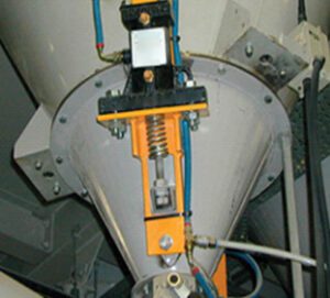
FIGURE 9. Arch-breaker devices provide direct contact with material to help mitigate material blockages at bin outlets
Cost. For small bins where one or two arch breakers are required, the cost for the units and installation are relatively low. The unit can be custom-made to accommodate a wide range of materials and bin and silo designs. Arch-breaking screens or bars designed to be in contact with the material when vibrating should be gentle so they will not degrade powders or granules. This setup is ideal for small bins where only one or two arch breakers would be required. However, large-diameter silos will require many arch breakers to be effective, which drives up costs — not just in the initial purchase and installation, but the long-term costs for generating compressed air or hydraulic pressure. While this energy consumption is often necessary for effective operation, it is a factor to consider in terms of overall operational costs and environmental impact.
Material flow. Arch-breaker devices do not promote mass flow or FIFO flow of material. They are also not appropriate for use with abrasive materials or materials with large particle sizes.
Space requirements. Depending on the design and size of the arch-breaker device, arch breakers may require a certain amount of space for installation. In situations where space is limited, the design and placement of these devices become important considerations.
Retrofitting onto existing silos. If material-flow problems form in an existing silo, installing arch breakers can be difficult, since half the device is inside the silo and half is outside the silo. Thus, access to the inside of the silo may be difficult due to confined-space issues.
Maintenance. Like any mechanical, pneumatic or hydraulic system, arch-breaker devices may require regular maintenance to ensure proper function. Maintenance activities could include inspections, lubrication and repairs, which may add to operational costs.
Direct material contact. In order for arch breakers to work, they must be in direct contact with the material being handled. Sanitary issues may arise because material may adhere to the arch-breaker screens or bars, making the system difficult to clean.
Live-bottom screw feeders
Screw feeders or augers can be used to extract and convey materials from silos. They are effective for handling both free-flowing and non-free-flowing materials.
Live-bottom screw feeders (Figure 10) are designed for use in large silos, bins and hoppers with large discharge openings. They typically use multiple feed screws together to create a “live bottom” to prevent bridging or cavern formation. If designed correctly, bulk materials can be drawn equally from the entire width and length of the inlet opening therefore creating FIFO flow. Some of the advantages of live-bottom screw feeders are described below.
FIGURE 10. Live-bottom screw feeders are best employed in applications with large discharge openings. They employ several feed screws in tandem to prevent the formation of bridges or caverns in the material
Controlled material flow. Unlike other silo-discharge devices, silo screw-bottom discharge systems are more than just a discharge device. They provide a controlled and regulated flow of materials from the silo, allowing for precise discharge rates.
Versatility. These systems are suitable for a wide range of bulk materials, making them versatile for various industries, such as agriculture, food processing and manufacturing.
Even discharge. If designed properly, screw-bottom discharge systems can contribute to an even and consistent discharge on a FIFO basis of materials, reducing the likelihood of uneven flow and potential blockages.
Automation potential. The operation of silo screw-bottom discharge systems can often be automated, improving efficiency and reducing the need for manual intervention.
Reduced segregation. The controlled discharge facilitated by screw systems helps minimize material segregation, ensuring a more uniform product.
There are also some potential issues associated with installing live-bottom screw feeders, as outlined in the following sections.
Maintenance requirements. Like any mechanical system, silo screw-bottom discharge systems require regular maintenance to ensure smooth operation. They can use multiple motors, reducers, bearings and seals that will require inspections, lubrication and occasional repairs.
Initial cost. The installation of a silo screw-bottom discharge system involves an initial investment, including the cost of the design engineering, equipment and installation. This can be a significant consideration for budget-conscious operations.
Energy consumption. Depending on the size and design of the system, there may be energy requirements associated with the operation of the screw mechanism, contributing to overall energy consumption.
Space requirements. Some silo screw-bottom discharge systems require additional space within the silo, potentially impacting the effective storage capacity.
Material compatibility. While screw discharge systems are versatile, it is essential to ensure that they are compatible with the specific characteristics of the stored materials, including particle size, moisture content and flow properties.
Potential for wear. The moving parts of the screw mechanism may experience wear over time, especially when handling abrasive materials. Regular monitoring and replacement of worn components may be necessary. ■
All images provided by Vibra Screw
Author
 Thomas Picone is director of business development at Vibra Screw Inc. (755 Union Boulevard Totowa, NJ 07512; Phone: 973-256-7410; Email: tpicone@vibrascrew.com; Website: www.vibrascrew.com). He is a graduate of Fairleigh Dickinson University and has more than 40 years of experience designing and engineering material-handling products and systems for bulk-solids processing and handling industries.