In your energy efficiency programs, don’t overlook air-pollution control and ventilation systems, which account for more than 25% of CPI energy consumption on average
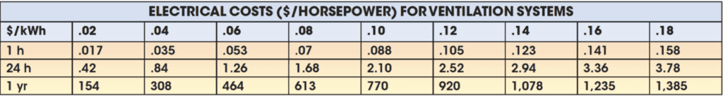
The cost to power fans and ventilators in the chemical process industries (CPI) is a significant consideration in efficient system design. More than 25% of the energy consumed in most CPI plants is used to power fans for ventilation and air-pollution-control systems. Annual operating costs for these units can easily exceed the initial capital cost of the equipment in two years, as shown in the table below. Compounding the problem, many systems lack sufficient capacity and fail to meet project requirements. The challenge for the design engineer is to develop a system that delivers sufficient air-handling capacity without consuming excessive power.
Centuries ago, Leonardo DaVinci and Daniel Bernoulli developed the mathematics and science for properly designed air-handling and emission-control systems. Yet, many systems designed today still do not meet current regulations after installation. In some cases, they may actually add to the health or safety hazards of the workplace. The operating costs for these systems are substantial, too — sometimes being more expensive than the equipment or process being controlled. Without proper planning and engineering, it’s easy to waste money on the initial cost of a system. When such waste is designed into the system, with excessive horsepower costs accumulating over the operating life of the system, a compounding result is inevitable. As in many engineering processes, these design shortcomings actually develop more from lack of communication, proper planning and organization than from errors in calculations.
Organization and project goals
Before designing a new air-pollution control system or a major alteration, it’s important to define the project goals and build a team to implement those goals. At a minimum the system must adhere to the following criteria:
- Protect the worker from the health effects of the process being controlled (meet all in-plant exposure requirements as provided by regulations or plant standards)
- Provide a safe connection to the process either through proper hood design or properly calculated direct connection to the process itself; this interface includes safety considerations for fire, explosion and process reactions as well as the ergonomics of process access
- Meet all emission standards of local and national regulations
- Operate with minimum energy and auxiliary costs (compressed air, natural gas, water, and so on)
- Operate with minimum replacement costs (such as filter bags and neutralizing chemicals)
- Provide an easily maintained and accessible system as required for reliable operation of the process
- Be simple to operate and supported by trained personnel to ensure ongoing optimum performance
These goals must be communicated to the design team and the construction organizations involved. Because pollution-control systems have an impact on the health and safety of the worker (and may also have legal implications), even small projects must meet this rigorous review. Smaller projects may have only a few plant people or designers involved in the process, but getting the right organization in place to implement these goals is key to success. Proper engineering, safety, maintenance, process operations and regulatory experts must all be involved at the onset of the project. If suitable personnel are not available in-house, then outside resources may be needed to supplement the team.
In all cases, the final goal of the project should be well defined so that the team understands how the system must perform and possession can be turned over to the plant for operation. These goals can include meeting certain regulatory requirements, minimum maintenance performance criteria (filter life in a baghouse, for example) and/or allowing for certain production levels from the equipment being controlled.
Managing waste and emissions
Before organizing and communicating for success, plant management should have policies for handling waste and emissions. Raw materials are brought into a plant and a finished product is shipped. Anything that cannot be sold or recycled is a waste to the system and should be eliminated or minimized.
Emissions are waste streams. The elimination of unnecessary waste streams by thorough investigation of the process and revisions is the first step in any design. Ideally this will either eliminate or minimize the need for exhaust. In some cases the need for an emission-control system can be avoided or at least reduced in scope. Only after all of the options for process changes have been made should “end-of-stack” solutions be considered.
Plant and process conditions
The next step is a realistic, current assessment of plant and process conditions. In most cases, plants have added air-pollution control systems and altered them over time as processes change. Often, no records of the total picture are available — only files of drawings and permits. Because government regulations are so varied, it may be difficult to determine if all present systems are in compliance or if there are unused resources in the plant that could be used to meet the new requirements. Thus, the best way to begin is with an audit of all of the air-emission points in the plant. These include the stack discharges of collection equipment, as well as roof ventilators and all possible sources of fugitive emissions from the building or storage areas. This evaluation should include the requirement for make-up air. Many systems fail or perform poorly because of inadequate make-up air supplies.
This air-emissions audit should locate and quantify the emission points. In addition to identifying all of the required emission-control points, it may also indicate where too much energy or air is being used for control. For example, a roof ventilator that is controlling fumes from a process will require large amounts of exhaust air and equal amounts of heated make-up air. Changing to a source capture system may necessitate an air-pollution control device (such as a scrubber or baghouse), but the reduced airflow will lower the make-up air requirement and attendant energy cost.
Similarly, there may be plant exhaust streams that can be cleaned sufficiently with redundant filtration systems to allow recycling of the exhaust back to the plant or process.
System power requirements
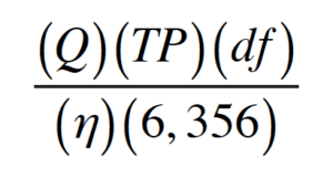
Power required for an air-handling system is computed with the following factors:
- Volumetric flowrate (Q), ft3/min
- Total pressure (TP), in. Hâ‚‚0: resistance due to friction in ducts, hoods and ΔP of control device
- Density factor of the gas being collected, (df), dimensionless
- Efficiency of the fan (η), dimensionless
These are combined into the Air Power Equation, where Power (in horsepower) is represented by:
Any increases in flow, system total pressure or density will increase power requirements. At the same time, an increase in fan efficiency can reduce power requirements. For example, a system handling twice as much air will require twice as much power to control the emissions with all other factors equal. Twice as much volumetric flow also requires larger ducts, control devices and fans.
Systems requiring more pressure (such as smaller ducts, which have more resistance, and certain collection devices, which require more pressure drop) will also increase power needs. Systems running at higher temperature (lower density) will require less power but may require larger ducts and more sophisticated control devices.
Careful manipulation of the factors in the equation can have cost-saving effects throughout the system’s useful life. However, there may be limits on the flexibility of design in this regard. The process itself may determine the requirement for airflow or location of control hoods, so there may not be a lot of room to reduce volumetric flowrate. Such inflexibility concentrates the focus for energy savings on making adjustments to the system pressure and fan efficiency.
System pressure is usually affected by two factors:
- Hood and duct resistance as a function of velocities in the system and the inefficiencies of flow (poorly designed hoods, short-radius elbows, branch-entry angles greater than 45-deg., abrupt contractions, and elbows and other interferences at fan inlets and outlets — collectively called fan-system effects): Figure 1 shows short-radius elbows and system effects that would add $6,500 in wasted power in this example.
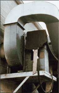
Figure 1. Fan system effects, such as short radius elbows, would add $6,500/yr in wasted power in this example
- Resistance across the emissions-control device: A baghouse that operates at a pressure drop of 8 in. H2O will require twice the power of a collector operating at 4 in. H2O. However, the lower pressure drop collector may not provide the filtering efficiency of the baghouse with higher pressure drop. Of course, it is possible to lower the pressure drop in a baghouse by adding filter area, but this option requires a larger housing. More importantly, baghouses often perform best at high pressure drops. The key is to minimize pressure drop while still meeting emission requirements. Excess static pressure just wastes power
So how does the design team find that narrow operating range of safe and efficient operation? There are tools beyond those that DaVinci and Bernoulli provided centuries ago. In the power equation discussed above, the three components that directly impact the calculation must be optimized. Volumetric flowrate and system pressure must be minimized, while fan efficiency is maximized. This is simple in theory but hard in practice. Any design must be cognizant of power through the whole design process because operational costs accumulate through the life of the system.
Minimize flow. The system must always meet the safety goals for the process and the operators. Systems directly connected to chemical processes are limited by the exhaust components from the process itself. However, other systems that capture emissions through fabricated enclosures or hoods can be optimized during the design process. Total enclosure of emission points may facilitate reduced exhaust volumes, minimizing worker exposure. However, a comprehensive enclosure may not be a good thing for process operators who have to deal with reduced visibility and more difficult manual access and maintenance.
Hoods that cannot be designed with total enclosure should be located as close to the source as possible. A side draft hood (Figure 2), located twice the distance from the source, can require as much as four times the exhaust volumetric flowrate. Hoods controlling emissions generated at high velocities (such as grinder wheels and saws) must be located so the opening is in the direct path of the dust, fume or mist. Several good references, such as Ref. [1] provide the equations and guidelines for good design of hoods, ducts and ancillary equipment.
Figure 2. Hoods that cannot be designed with total enclosure should be located as close to the source as possible. A side-draft hood, located twice the distance from the source can require as much as four times the
exhaust volumetric flowrate
It’s important to note that other factors such as explosive limits for the gas being collected, moisture content (dew point) and heat content may set the air volumetric-flowrate requirements, thereby limiting the optimization.
Minimize pressure. The designer has many more opportunities to control this factor in the power equation. Providing a system with good airflow characteristics (properly specified ducts with optimized velocities and sizes), selecting the proper control device and using control techniques such as variable-frequency drives and pressure monitors can help keep system pressure managed.
Bag houses and other filtration devices have varying pressure drops over the life of the system. Bags are generally more efficient with more pressure drop, but they also use more energy. Scrubbers, oxidizers and electrostatic precipitators tend to operate at more constant resistance. In either case, a good pressure-monitoring system that controls system volumetric flowrate can save thousands of dollars every year on the operation of even medium-sized systems. As variable-frequency drives become less expensive, they are now being found on many installations, especially those over 20,000 ft3/min in size.
Control density. In the power equation there is a gas-density factor. Temperature, moisture, molecular weight, altitude and the absolute pressure in the duct or vessel affect the density of the transporting gas. In many cases, a change in one condition will be offset with an accompanying change in another condition. For example, the moisture added in evaporative cooling decreases density by increasing moisture content; but cooling the gas increases density.
Similarly, a density change affects other physical characteristics of the system. Again, evaporative cooling reduces the actual flow of gas as density changes. This increase in density (and needed power) may be more than offset by reduced initial costs from smaller ducts, control devices and fans (as well as lower the value for volumetric flowrate in the equation). Cooler temperatures may also allow use of lower-cost collectors, fans and peripheral devices.
Fan efficiency. The denominator of the power equation includes a factor to reconcile the units with fan efficiency. Obviously, efficiency affects power usage inversely. However, there are limits on what a fan can deliver. The design of the fan and its blade type can greatly affect efficiency. Meanwhile, the fan’s peak point of efficiency measured in a laboratory may not necessarily be the most stable point of operation. If peak efficiency coincides with the peak of the pressure curve, then there may be operational problems as volumetric flowrates vary with only minute changes in system pressure. The designer must consider both curves when choosing the best fan and operating point to optimize reliability as well as power usage (Figure 3).
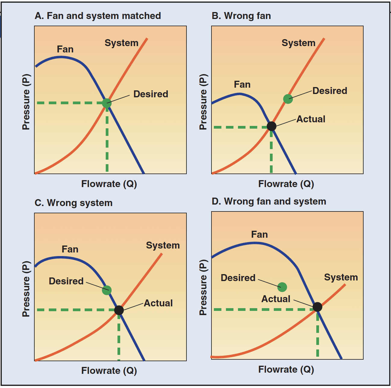
Figure 3. A fan’s peak point of efficiency may not be the most stable point of operation.
Both the fan and system curves must be considered when choosing a best
fan and operating point to optimize reliability as well as power usage
Summary
Energy usage by ventilation and process control systems has forced designers to be cognizant of all factors that can affect power requirements. The power equation identifies four main areas — volumetric flowrate, pressure, density and fan efficiency — that affect energy consumption. If not properly designed, system inefficiencies will accumulate significant wasted costs during the life of the equipment and may actually overwhelm the system profitability.
The process to reduce energy costs begins with a philosophy to minimize waste and an awareness of the basic principles of air system design. The challenge for industry today and in the future will be to operate in the narrow functional range that guarantees system effectiveness at minimum energy consumption. An optimum solution from the Air Power Equation can help meet those goals.
Reference
1. “Industrial Ventilation — A Manual of Recommended Practice,” American Conference of Governmental Industrial Hygienists Committee on Industrial Ventilation, (ACGIH), 1986.