Process electrification is gaining interest as a solution to industrial CO2 emissions, which account for 20% of total CO2 emissions in the U.S. [1]. Several technologies are emerging for electric process heating, including electrode steam boilers and high-temperature heat pumps, but the simplest and most widely deployed form of electric process heat uses a simple resistive-heating element. This one-page reference discusses the benefits, limitations and design considerations for electric resistive heaters.
History
Electric resistance heaters were invented in the 1890s, shortly after the lightbulb. A 1914 patent from Edwin Wiegand sheathed the resistor with refractory material and a protective metal tube, preventing the element from being shorted out by a process fluid (Figure 1) [2]. This design resembles the modern form and enabled electric heaters to begin being deployed in the nascent chemical process industries (CPI). Modern implementations resemble shell-and-tube heat exchangers, with the process being heated on the shell side of the exchanger, and the tubes themselves replaced with long electric heating elements.
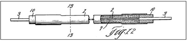
FIGURE 1. The diagram shows an early resistive-heating element with insulating refractory material and a protective metal sheath (diagram credit: Ref. 2)
Advantages and disadvantages
Deploying electric heaters can dramatically reduce a facility’s greenhouse gas emissions. A process with a heat demand of 40 MW absorbed (80% thermal efficiency, higher heating value (HHV)) will emit 79,000 metric tons (m.t.) of CO2 per year. Replacing a fired heater with an electric heater can reduce these emissions to almost zero, if low-CO2 electricity is available. For example, with abundant nuclear and hydroelectric energy, Sweden has an electricity emissions factor of ~13 kg CO2/MWh [3]. If this process was deployed there, it would have indirect emissions of 4,600 m.t. of CO2 — meaning electrification would reduce emissions by 94%. In contrast, the electricity emissions factor in the U.S. is 350 kg CO2/MWh [4], so a 40-MW process deployed there would have indirect emissions of 122,600 m.t./yr — meaning electrification would instead increase emissions by 55%.
Regardless of the grid average, low-CO2 electricity can often be secured, allowing a site to mitigate most of its process-heating emissions. Industrial decarbonization objectives have been driving increasing deployment of electric heaters, even at previously unheard-of sizes (5–10 MW) in the U.S. in the past several years.
In addition to lowering CO2 emissions, electric heaters excel when a small capacity (<1MW), drop-in, and easy-to-control heater is needed, and in areas where natural gas is expensive or unavailable.
Cost is currently a significant disadvantage with electric heaters. In the 10–20-MW size range, the purchased equipment cost of an electric heater, and associated control/circuit panels, is expected to be roughly 3–5X the price of a traditional fired heater. Costs for large (>1 MW) electric process heaters are likely to fall somewhat with optimized designs and economies of scale, but costs also reflect the requirements of electric heaters for large amounts of heat-transfer area, steel and copper wiring.
Heater design
Opportunities exist for significant optimization of the designs for large electric process heaters. First, a choice must be made between direct electric heating or indirect electric heating with a heat-transfer fluid or steam. Direct electric heating is chosen when very high temperatures are needed (>400°C), or when a small, inexpensive system is desired. Indirect heating is generally chosen otherwise, because it allows isolation of the process, centralization of utilities and flexibility to use multiple heat sources (waste heat recovery, for example).
Selection of steam or an organic heat-transfer fluid is a complex choice. Briefly, steam systems have high heat flux in the electric heater (~50 W/in.2) but are practically limited to temperatures below ~250°C and have high maintenance costs (due to water treatment and corrosion). On the other hand, heat-transfer-fluid systems generally require a lower heat flux (~20 W/in.2) in the electric heater, but allow operation up to 400°C with generally lower system capital and operating costs due to the lower system complexity and generally non-fouling, non-corrosive hydrocarbon chemistry.
When designing an electric heater, the key degrees of freedom are the heat flux of the electric heating element and the flowrate of the fluid across the heater. This is a balance between how much heat the resistor will produce, and how quickly the fluid can convect the heat away from the element’s surface. Higher-flux elements will reduce the overall capital cost of the heater, but an excessive heat flux can cause element damage and fluid degradation.
Care should be taken to not exceed a heat transfer fluid’s maximum film temperature at the element’s surface. High fluid flowrates and selection of a fluid with inherently higher thermal stability can provide a safety margin that enables a designer to increase the element heat flux, thus reducing the overall cost of the system. n
Editor’s note: This column was authored by Kent B. Fischer, Ph.D., Eastman Chemical Company, Kingsport, Tenn.
References
1. U.S. Energy Information Administration (EIA), www.eia.gov, 2025.
2. Wiegand, E., Method of producing electrical heating elements. U.S. Patent, US1669385, 1928.
3. Wiertzema, H., et al., Frontiers in Energy Research, 8:192, 2020.
4. U.S. Environmental Protection Agency, Emission Factors for Greenhouse Gas Inventories, www.epa.gov, 2025.