Reduce the problems associated with handling hazardous liquids by following these guidelines
Pumps are one of the most ubiquitous items of equipment found in chemical processing plants. Often, they are used to transfer hazardous liquids, such as flammable, combustible, toxic and corrosive chemicals. In order to ensure safety during pumping, certain design and operating practices should be followed. This article discusses safe practices for centrifugal, positive displacement and sealless pumps.
Potential Problems and Hazards
A number of problems and hazards can occur during the pumping of hazardous liquids. These can include the following:
- Mechanical seal failures resulting in leaks or fugitive emissions
- Deadheading
- Reduced or low flow in centrifugal pumps
- Overpressurization
- High temperature
These problems and hazards can result in severe incidents, such as fires, explosions and toxic releases, if they are not addressed by preventive or protective measures. The following sections discuss these issues, as well as recommended practices to eliminate or minimize problems for various types of pumps.
General Recommendations
Materials of construction
Materials of construction should be chosen based on the corrosive properties of the liquid being pumped. At a minimum, pumps should be constructed of cast steel. All the components of the pump (casing, impeller, mechanical seal or packing and other trim) should be compatible with the liquid being pumped. Cast iron should not be used for hazardous liquids, at pressures above 200 psig or temperatures above 175°C. Cast iron is brittle and can be cracked by mechanical or thermal shock, which could result in leaks and subsequent fires. Ductile iron is also appropriate for some applications, but it should be noted that ductile iron, when exposed to high temperatures produced by fires, can revert to cast iron, and should be avoided if there is any risk of fire. The pump casing, impeller and other moving parts should be constructed of non-sparking materials if the pump will run dry at frequent intervals.
Pump location
Pumps should be installed and located in a way that facilitates safe maintenance. When they are intended to handle hazardous liquids such as toxic, pyrophoric or water-reactive liquids, pumps should not be located beneath main-plant pipe racks. If a fire occurs at the pump, flames could reach the piping above and overpressurize the fluid contained in the piping or stress and weaken the piping due to heat absorption. Pumps, especially those handling hazardous liquids, should be located in open, well-ventilated areas to prevent accumulation of leaking hazardous vapors. In the design of tank farms, many companies prefer to situate the transfer pumps outside of the dike with a separate curbed and drained area to prevent the spread of seal or packing leaks. In the event of a large spill, the pumps may become submerged as a result of the normally high dikes used in tank farms. For some chemicals, depending on the properties of the liquid, such as flammability and corrosiveness, fire or mechanical damage to associated electrical equipment could occur when the pump is submerged. In special circumstances, such as when handling high flash point, combustible liquids or viscous liquids that necessitate a short suction line, the pump may be located inside the dike wall. In this case, a local motor start-and-stop control station should be provided outside the diked area and properly identified. Also, consideration should be given to locating the pumps in a subdivided area for containment of seal or lube-oil leaks.
Backflow protection
Backflow can occur in a pumping system when the motor (or other driver) is stopped, either intentionally or accidentally. Depending on what type of pump is used, this may result in the flow of the pumped liquid through the pump to the suction vessel and possible vessel overflow. It may also result in reverse rotation of a non-running installed spare pump, which could cause damage. To avoid or limit backflow, a check valve should be installed in the pump discharge line. For highly hazardous liquids, it may be desirable to install two check valves in series. Alternatively, a fast-acting open-shut valve, activated by a low-pressure sensor in the discharge line that will shut the valve tightly, can be used. When check valves or fast-acting open-shut valves are used in the discharge line of a pump, it may be necessary to establish a way to prevent hydraulic hammer.
Pump piping and valves
Pump suction and discharge piping should be supported independently of the pump. Supports should be designed to ensure that the pump flange loadings are minimized and do not exceed the loadings specified by the pump manufacturer. Additionally, the pipe supports should be adjustable.
| Selection Criteria | Magnetic Coupling | Canned Motor Pump |
|---|---|---|
| How safe is the unit during failure? | Restricted: unit has only one sealed liner; if liner ruptures, the fluid escapes into the atmosphere | Extended: two boundaries exist, the can and the motor housing; if the can ruptures, the motor housing takes over as a gas-tight barrier |
| Applications | Restricted: limited by the rotating mass and construction size | Extended |
| Viscosity range | Restricted: an increase in viscosity establishes relative limitations | Extended: the fluid is warmed going through the motor section, allowing the pumping of higher viscosity material |
| Total viscosity | Equal | Equal |
| Temperature limitation | Restricted: limited to applications between 100 and 754°F | Extended: can be used at temperatures between – 200 and 1,000°F |
| Temperature control | Restricted: only the pump can be insulated and traced | Extended: both the pump and the motor can be insulated and traced |
| Maximum operating pressures | Restricted: the can thickness limits the maximum pressure | Extended: the achievable working pressures are independent of the can thickness because support can be furnished outside of the gap, the current limit for system pressure is approximately 17,000 psi |
| NPSH required | Better: the lower heat input to the recirculation stream assures better net positive suction head (NPSH) characteristics | Worse |
| Explosion protection due to leakage | Restricted: see comments under row 1 | Extended |
| Repair of motor | Better: uses a standard motor | Worse |
| Sensitivity to solids | Worse: units are more sensitive to solids, especially when ferrous particles are in the fluid | Better: Units are available with slurry designs, which isolate the motor section from the pumped fluids |
| Starting problems | Can exist: extreme care must be taken in applying the torque requirements to these units | Not normally |
| Noise levels | Greater: much higher levels due to the fan on the motor and the additional bearings in the coupling | Lower: these pumps are especially quiet; cooling, coupling, and bearing noises do not exist |
| Overall length | Greater | Less |
| Flexibility of installation | Restricted | Extended: units can be installed either vertically or horizontally in generally a much smaller space |
| Interchangability with standard chemical pumps | Depends on individual manufacturer | Depends on individual manufacturer |
| Electrical installation | Depends on individual manufacturer | Depends on individual manufacturer |
| Cost of manufacture | Greater | Less |
| Foundation | Required | Not required |
| Coupling | Yes | No |
| Coupling guard | Yes | No |
| Coupling alignment | Yes | No |
| Cost of repair | Less: the repair of the pump and the coupling can usually be accomplished by normal maintenance mechanics | More: repair requires mechanical as well as electrical knowledge |
| Bearing wear monitors | Not normally available | Widely used |
The piping should be designed to withstand the maximum pressure generated by the pump at “deadhead” conditions. Pump piping that accommodates hot liquids is often required to provide flexibility for thermal expansion and contraction. If possible, this should be provided through design of the piping itself with adequate area for piping loops. If not, then this flexibility can be achieved through the use of flexible hoses or expansion joints, which should be constructed of a fire-resistant material. If expansion joints are used, they should be of the packless type, without circumferential welds in the bellows. Shutoff valves on the suction and discharge of the pump should be provided. If the suction vessel is nearby, the pump shutoff valve should be mounted on the vessel nozzle. This can prevent dumping of the vessel contents in the event of a fire near the suction line, given that the valve is closed at the time. Lines in which there is no flow may fail quickly when exposed to fire. If the pump has a long suction line, shutoff valves should be provided near both the pump inlet and at the suction vessel. Fire-safe valves should be used when a loss of valve integrity due to a fire would result in a large leak of hazardous liquid. Shutoff valves that can be operated from a remote location should be used for critical applications, for example, when large releases of hazardous liquids could occur upon pump failure. The actuation devices for these valves should be located in safe, peripheral areas, such as control rooms or in service racks outside of unit battery limits. Interlock remotely operated shutoff valves to automatically shut down the pump when the valves are closed.
Other safety considerations
- Provide warning lights on location for pumps that are remotely or automatically started
- Clearly identify pump shutdown and start-stop switches regardless of whether the switch is local or remote, and provide lockout capability at the pump driver or power source
- Provide a shaft-coupling guard for all pumps with exposed shafts
- Allow for the safe drainage of the pump casing and the suction and discharge piping for all pumps. Provide schedule 160 (or heavier, when necessary) casing drains and casing vents for pumps handling hazardous liquids. These should be socket or seal welded, and terminated at a raised-face flange or socket-weld fitting
- Monitor pump-bearing temperature with alarms and/or motor shutdown at high temperature. Lack of lubrication can result in high bearing temperature and possible failure, which in turn can lead to shaft misalignment and mechanical seal failure
- A temperature sensor should be installed in a pump casing if the pump is handling a temperature-sensitive liquid. The sensor should be interlocked to shut the motor off when the high-temperature limit of the liquid is reached
- Pumps handling flammable liquids should be properly bonded and grounded to prevent electrostatic ignitions
- The seal areas of pumps handling corrosive liquids may require spray shields for personnel protection
Standard Centrifugal Pumps
Standard centrifugal pumps are usually provided with either packing or mechanical seals. For pumps handling hazardous liquids, packing should not be used. It is recommended that double, inside mechanical seals or tandem mechanical seals be used with a compatible buffer liquid between the seals. The following hazards can occur with standard centrifugal pumps:
- Mechanical seal failure
- Reduced or low flow
- Overpressurization
- High temperatures
- Cavitation
These hazards and their preventive and protective measures are discussed below.
Mechanical seal failure
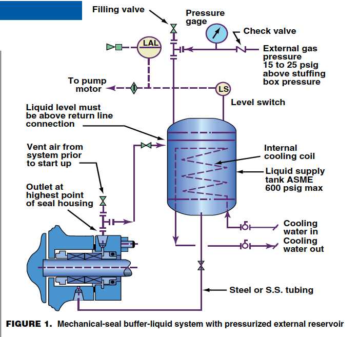
A mechanical seal failure can result in fugitive emissions or large spills of hazardous liquids, problems that could lead to fires or explosions. One cause of failure is the loss of flow of the buffer liquid through the seal. This can be avoided by creating a buffer-liquid seal system that consists of a circulating, pressurized reservoir with an internal cooling coil and a low-level alarm. Figure 1 is a schematic of such a system for a double mechanical seal. If there is a seal failure, pressure on the reservoir will force the liquid either into the process fluid or out of the seal on the low pressure side, and the liquid level in the reservoir will show an abnormal level drop. The level switch in the seal-liquid reservoir should be connected to an alarm and interlocked to the pump motor, or other driver, to shut it down. It may also be desirable to close the valve at the supply-vessel nozzle or at the pump-suction inlet. With tandem mechanical seals, the buffer liquid is usually at atmospheric pressure or slightly higher, and a failure of the inner seal will result in rapid filling of the reservoir with process liquid. A high-pressure or liquid-level switch in the reservoir should be installed to alarm and shut down the pump motor. Mechanical-seal failure can also be caused by corrosion products and other particle debris in the liquid being pumped, so measures should be taken to remove these from the liquid, such as providing an adequate strainer in the pump-suction line.
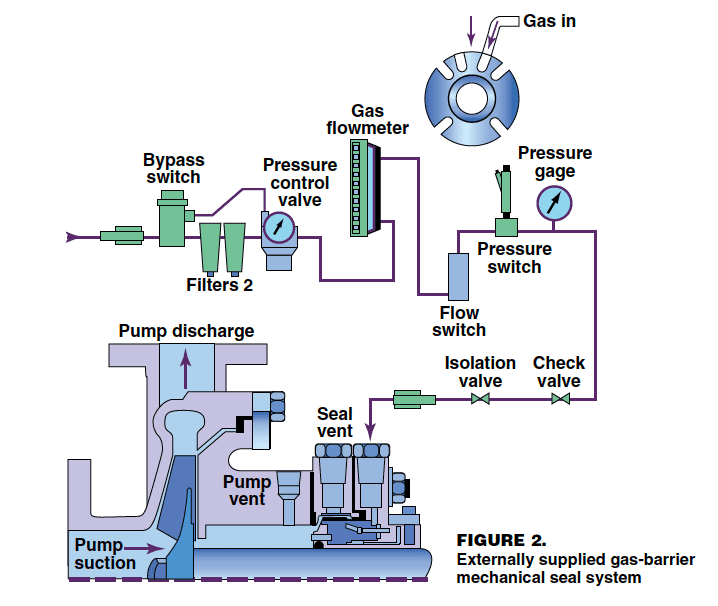
API STD 682 [ 1] gives additional information on pump mechanical seal systems. In recent years, gas-barrier seals have been used in place of buffer-liquid seals in many applications and should warrant serious consideration. Gas seals operate on a gas fluid film and do not generate significant frictional heat. Unlike in single mechanical seals, the process fluid is not the lubricant, and unlike in double and tandem mechanical seals, a compatible barrier liquid is not required. Gas seals use either compressed air or nitrogen as the barrier gas. With gas-barrier seals, liquid seal reservoir maintenance costs, specialized refilling procedures and their impact on reliability are eliminated. Figure 2 is a schematic of a gas-barrier seal system. More on these systems is found in Ref. [ 6]. Another possible cause of mechanical-seal failure is shaft misalignment. The appropriate alignment techniques should be used to check pumps prior to startup, and the alignment should be rechecked if continuous bearing or mechanical-seal problems occur. Dial-indicator alignment and laser-optic alignment are the two available methods of laser alignment. Laser-optic alignment systems have several advantages over dial-indicator systems. When time savings, reduced downtime, increased reliability, fewer repair costs and lowered electricity costs are all considered, a high-quality, laser-optic alignment system is clearly the better choice. The main disadvantage of a laser-optic alignment system is the high up-front cost of the system in comparison to a dial indicator system. Bloch [ 4,5], Piotrowski [ 9] and API RP 686 [ 3] are good sources of information on this technology.
Reduced or low flow
Operation of centrifugal pumps at severely reduced flow or at shutoff should be avoided. Frequently, instability points are reached as pump flow is throttled. An unstable flow condition many be encountered at flows of 50 — 60% (or lower) of flow at the best efficiency point of the pump. This instability condition can cause excessive vibration and damage to pumps, drivers, couplings, gears, piping and adjacent equipment. Therefore, centrifugal pumps should be provided with a minimum-flow recirculating (bypass) line from the pump discharge side of the pump, located upstream of the block and check valves. This bypass line should preferably be routed back to the pump supply vessel if it is an adequate “heat sink.” Otherwise, the minimum flow bypass line should be routed through an external cooler before returning to the supply vessel or pump suction. This cooling of the pumped fluid is required because a centrifugal pump will raise the temperature of the fluid being transferred due to the pump’s mechanical work on the liquid, such as efficiency losses. The effect ranges from a small temperature rise during normal operations to a high temperature rise when the flow is completely stopped. The minimum flow requirements should be obtained from the pump manufacturer. There are a number of methods available to detect low-flow conditions, including the use of a flow sensor in the pump suction line, an ammeter to measure the draw of the motor and a power monitor to measure the motor horsepower. These sensors can be interlocked with the motor to shut it down upon the detection of reduced or low flow, more details of which are discussed by Volk [ 11].
Overpressurization
Overpressurization protection from thermal expansion is needed for centrifugal pumps that can be valved-in when there is remote startup capability or when the suction and discharge lines both have automatic closing valves. The pump generates heat, which will cause liquid expansion and possible vaporization, leading to excessive pressure if the heat is not removed. Overpressurization protection is also needed if the pump shut-off head exceeds the pressure rating of the system piping. Overpressurization relief is usually provided by a pressure relief valve in which discharge is directed back to the pump supply vessel. With liquids that can polymerize, however, pressure relief valves may not operate properly, so the use of a rupture disk should be considered.
High temperature
As discussed above, high temperatures can occur when a pump operates against a closed valve, which is known as deadheading. This is a very dangerous situation, as excessive temperatures can lead to decomposition reactions and subsequently to an explosion. When pumping such high-hazard liquids, it is very important to provide a temperature sensor in the pump casing that will alarm and cause the motor to shut down before a thermal runaway occurs.
Cavitation
Cavitation can cause pressure variation, shaft deflection, vibration or mechanical shock that will damage seal components. These problems can be avoided by proper design of supply vessels and suction-piping systems. It is especially critical to ensure that the pump has adequate net-positive suction head (NPSH) and that entrained gases are avoided. NPSH requirements should always be obtained from the pump manufacturer.
Positive-Displacement Pumps
Positive-displacement pumps comprise two main categories: rotary and reciprocating pumps. Some rotary types commonly used in the chemical process industries are gear, lobe, screw, vane, progressing cavity and peristaltic pumps. The reciprocating types are piston (or plunger) and diaphragm pumps. Rotary pumps that handle hazardous liquids usually have mechanical seals, and the hazards and protective measures that are discussed above for centrifugal pumps apply to rotary pumps as well. Most positive-displacement pumps require a pressure relief device to protect against overpressure, which can be caused by a closed discharge valve or restricted discharge line. External relief valves are typically used, because they are easy to see when open, can easily be adjusted to any set pressure, and remain open only long enough to relieve pressure, thereby reducing process liquid loss. The relief device discharge should be sent back to the supply vessel, or if being recycled back to the pump suction piping, an external cooler should be installed to remove any heat input to the liquid from the pump.
Positive-displacement pumps are sometimes provided with an internal relief valve. A major drawback is that an internal relief valve does not dissipate heat. Even if the pump comes equipped with an internal relief valve, it is strongly recommended that an external relief valve also be used when handling hazardous liquids. An external relief device should be located as close as possible to the pump discharge nozzle and before any block valve. If the pump is handling a slurry or a chemical that might possibly polymerize, a rupture disk should be installed, as a backup in case the relief valve plugs. Diaphragm pumps are used for many hazardous-liquid handling applications, because they have no mechanical seals or packing and are essentially sealless pumps. They can be either motor-driven or air-operated, and can have either single or double diaphragms. Since single-diaphragm pumps can leak if the diaphragm fails, double-diaphragm pumps are recommended for highly hazardous liquids. The space between the two diaphragms can be fitted with any of several leak-detection sensors (using a pH, liquid conductivity or pressure sensor), which will detect a problem and set off an alarm when the primary diaphragm develops a leak or fails. Air-operated diaphragm pumps usually vibrate because of their mode of operation. Therefore, the suction and discharge piping should not be hard-piped to the pump nozzles, but should have flexible hose sections. The hoses should be able to move enough that the movement of the pump caused by vibrations is offset. If the hoses are not long enough to provide movement, they become comparative to hard-piping and can cause damage to the pump. It is recommended that the hoses be a metal-braided type rather than rubber hoses.
Progressive-cavity pumps are widely used for transferring slurries, viscous liquids and highly hazardous liquids, such as water-based explosives. Tests by explosives companies and investigations into incidents have shown that this type of pump can develop dangerously high temperatures when operated deadheaded or dry. In some incidents and tests, explosion or detonation of the explosive (or residual explosive) in the pump resulted. To address this operational problem, One manufacturer has developed and patented a progressive cavity pump stator (made of a urethane compound) that gives excellent service life at normal pumping temperatures but melts before typical ammonium nitrate decomposition temperatures are reached. When the stator material melts, the heat-producing interference with the rotor is reduced so that the high temperature is reduced. The development of this new stator design, resulting in improved safety, is discussed by Osborne [ 8]. This new design may also be applicable to the pumping of other highly hazardous liquids.
Sealless Pumps
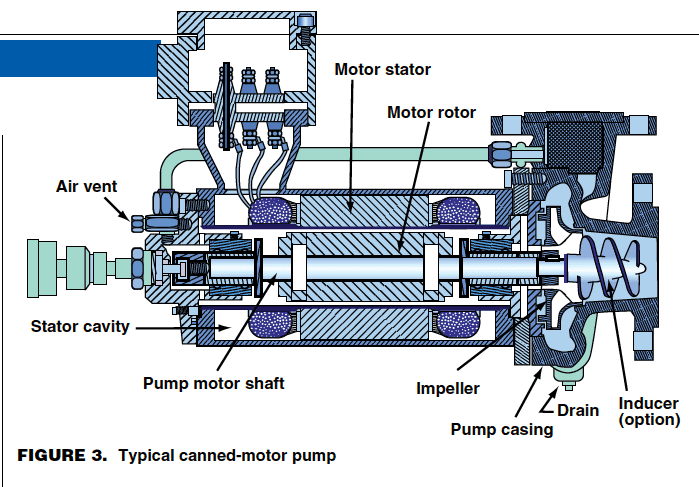
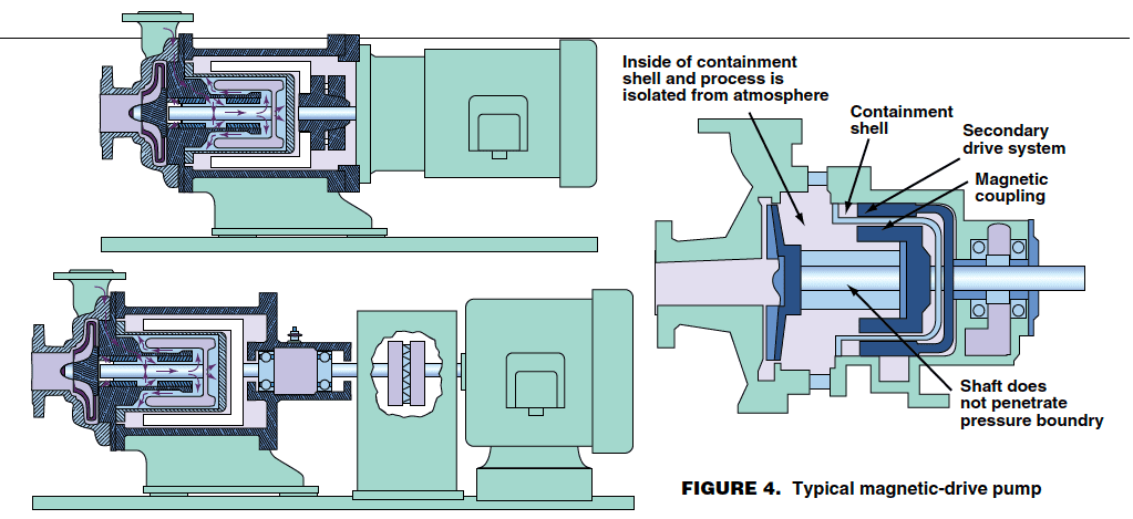
Two kinds of sealless pumps are available: canned-motor and magnetic-drive types, which are compared in Table 1. As the name implies, sealless pumps do not have any packing or mechanical seals, and are therefore much less likely to have leaks of hazardous liquids. Centrifugal and rotary positive-displacement pumps are available as sealless pumps. The difference between canned-motor pumps and magnetic-drive pumps lies in how the rotor is driven. A canned-motor pump, as seen in Figure 3, has a standard a.c.-induction motor stator separated from the pumped liquid by a non-magnetic membrane. The electrical rotating magnetic field of the stator drives the rotor, as in any standard a.c.-induction motor. The membrane is in what would normally be the “air gap” (the space between the rotor and stator) of the motor, and causes the air gap to be larger than normal. A magnetic-drive pump, as seen in Figure 4, has a rotor containing magnets mounted outside and concentric to the containment shell, also known as the “can.” This rotor, which contains a series of powerful magnets, is mounted on a shaft that is driven by a separate motor. The external rotating magnetic field, rather than electrical induction, drives the inner rotor. Magnetic-drive pumps can be divided into two sub-groups, based on inner-rotor construction. These two types are synchronous (also called “permanent magnet”) pumps and eddy-current pumps. Specially designed magnetic-drive pumps are available with dual-containment shells. Sealless pumps are available in a wide range of magnetic materials, along with various metallic and non-metallic containment-shell materials.
| Cause | Effects | Results | Type of Monitor Available |
|---|---|---|---|
| Dry-running (worst possible condition — no flow in any part of the pump) | Rapid temperature rise of containment shell | Ultimate, if not immediate failure | Flow switch |
| Decrease in horsepower | Pressure switch | ||
| Accelerated bearing wear | Power/current sensor | ||
| Temperature monitor | |||
| Closed Discharge Valve (no discharge flow, but fluid circulates through shell area) | Temperature of containment shell fluid will rise | Failure will depend on length of time pump is operating in given condition | Flow switch |
| Decrease in horsepower | Power/current sensor | ||
| Highest discharge pressure | Temperature monitor | ||
| Decoupled (inner magnet is not rotating, no flow but pump is wet) | Temperature of containment shell will rise | Failure will depend on length of time pump is operating in given condition | Flow switch |
| Decrease in horsepower | Power/current sensor | ||
| Worn sleeve bearings/shaft inside pump | Wear has reached maximum, causing inner magnet to offset and rupture containment shell, and impeller to contact volute | Failure (possible leakage) | Bearing wear monitor |
| Vibration monitor | |||
| Worn roller/ball bearings (in power frame) | Outer magnet is offset and contacts containment shell (possible rupture) or other part of the pump housing | Leakage through containment shell | Temperature monitor (based on friction heat) |
| Vibration monitor |
Although these pumps do not have a mechanical seal or packing and are normally much less likely to leak, there are two weak points in sealless pumps that can result in serious leakages. These weak points are the containment shell and the bearings. The containment shell is usually fairly thin to allow enough of the magnetic field to pass through the can to drive the pump. Thus, if the rotor bearings, which are internal and lubricated by the pumped liquid, wear enough to cause the rotor to rub against the can, the can may become punctured and rupture. This will cause considerable and uncontrollable loss of the liquid being pumped. A number of pump manufacturers address these potential problems with innovative design features. Some pumps are constructed with an outer shell that serves as a secondary containment should the can rupture. Some pump manufacturers provide a sensor well in the secondary containment shell for a moisture-sensing probe, which can be interlocked to an alarm and possibly to the motor to shut it down. Another safety option is the incorporation of a mechanical seal between the radial ball bearings and the secondary containment housing. On most sealless pumps, sensors are available to detect bearing wear and failure, as well as monitor high can temperatures. Several operating precautions should be observed to minimize potential problems when using sealless pumps. Low-boiling liquids may flash when circulated through the internal bearings and rotor assembly, resulting in vapor binding of the pump when the liquid is returned to the lowest pressure zone at the back of the impeller. This can usually be prevented with canned-motor pumps by using a reverse circulation system and returning some liquid back to the suction tank that feeds to the pump. With magnetic-drive pumps, a reverse circulation system cannot be as easily installed because the can is blinded on the back side by the external magnetic drive. However, a small bypass stream can sometimes be taken off the discharge end, cooled externally and then injected back into the can area. Another possible cause of failure is the existence of solids in the pumped liquid. This can create problems with the internal lubrication system, as the solids can constrict or block passageways entirely. Various pump manufacturers use different methods to handle this problem, such as self-cleaning strainers, and a piping arrangement similar to mechanical-seal piping that includes strainers, separators, and external flushing. It is very important to avoid running sealless pumps dry, as this can result in worn bearings and internal rotor galling, or ripping the open can. A number of different types of monitors and sensors are available to detect a dry-running sealless pump. Table 2 lists causes of sealless pump failures and their effects and lists types of failure detection monitors for sealless pumps. See Nasr [ 7] for a discussion of temperature monitoring, motor monitors and bearing wear monitors, and Refs. [ 2, 10] for additional information on sealless pumps.
Acknowledgments The author would like to thank the following individuals who provided me with technical material that was helpful in writing this article: Heinz P. Bloch (Process Machinery Consulting), Henry Febo (FM Global), Alfred M. Osborne (Dyno Nobel Inc.) and Robert Walz (ABB Lummus).
Edited by Kate Torzewski
References
|