A major part of field work lies in troubleshooting problems: finding out why a system is not operating the way it is intended. This article provides guidelines for effective troubleshooting and contains many practical examples of their successful use
Effective troubleshooting in the field requires not only skillful engineering but also an equal dose of the right behavior. Together, these qualities represent a combination of “art and science” that will get the troubleshooting job done well and done quickly.
Field troubleshooting is not for everyone, but if you like a challenge, it may be for you. Troubleshooters are always in demand when equipment goes down or is not making product the way it should. They are brought in to solve problems that have defeated on-site personnel.
It is much like crime scene investigation on television. It’s the engineering equivalent of detective work, tracking down the felons that are causing problems. When it is done effectively, everyone walks away satisfied.
A blend of science and art
A wise mentor once said that troubleshooting involved breaking the problem in half and breaking it in half again. His trade involved test trains for combustion gas analysis. Each train contained perhaps 20 ground glass joints, which were prone to leaks. Our mentor could have checked each one, with an average of 10 steps to find the leak. But using his heuristic, the math says we can find it in, at most, five steps (the leak is in joints 1–10 → 1–5 → 3–5 → 3 or 4 → 4, bingo!). The bigger the system, the greater the reduction in the number of steps needed to find a leak, or a break in a series wiring system (think Christmas lights), compared to a linear search.
Having the right tools is important, too. They need not be expensive, but it helps if you have them in your gear bag ready to use. Figure 1 shows (left to right) a Pitot tube for flow measurement, a measuring tape, pipe-thread-to-barbed tubing adapters and connectors, a digital manometer, thermocouples and a field readout, a hand-held infrared temperature probe, a clamp-on ammeter and multimeter, a combination pressure/vacuum gage, a roll of electrical tape, and of course a flashlight. They will help you get the hard data you need to back up your hunches. One can also use bigger and more expensive tools, like the combustion test system shown in Figure 2, to provide fast feedback on what is going on inside the process. For those who want to learn about the wide variety of tools used by many trades, government training manuals and other source materials are available online [1, 2].
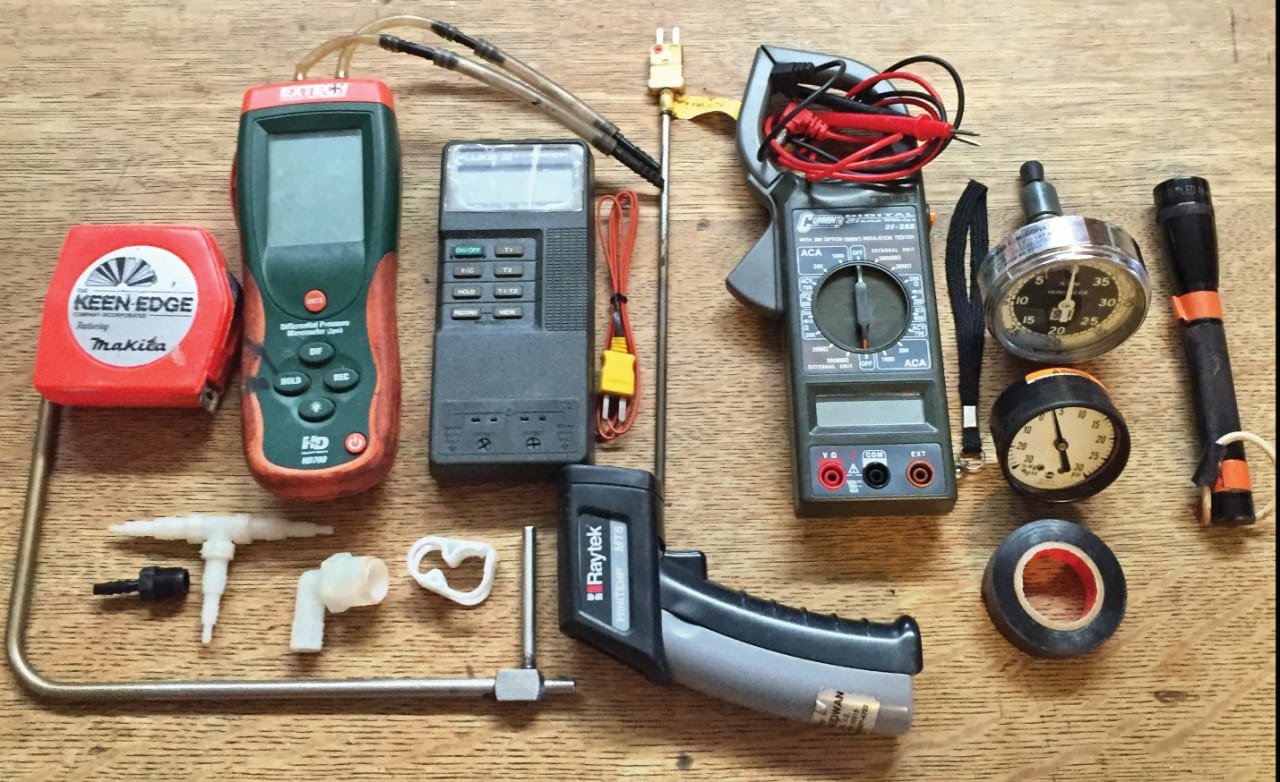
Figure 1. Troubleshooting may require a variety of test equipment — some typical items are shown here

Figure 2. More-specialized equipment includes this portable combustion analyzer
The “art” side of troubleshooting includes being a good listener, being observant, taking time to think over information, taking action, opening things up to look at them, and being willing to get dirty to get the job done. The science side includes doing calculations, testing the system, and comparing the results to what was expected in the design.
The following is a litany of field problems encountered and solved in the experience of the authors by employing the guidelines suggested in this article.
Those pesky valves
Each type of valve has its own set of quirks, and many an engineer has learned to distrust all types. Here are two examples of ball valves that did not operate as expected.
Valve failure makes scrubber pre-quench inoperative. A brand-new solid-waste incinerator was failing particulate-matter stack tests, despite being equipped with a state-of-the-art venturi scrubber and packed-tower acid-gas absorber. After three failed stack tests, we were called in to fix the problem. First step was to get the stack test data. It was horrible. Emissions exceeded the normal particulate-matter guarantee — with no air pollution control — of 0.08 grains/dry std. ft3 (180 mg/dry std. m3). We called the test company to ask about the M5 filter paper used in the test: what did it look like? They said it had a heavy coating of white dust. The heavy coating was no surprise, but white dust? From an incinerator? This was the first clue, since the expected color would range from brown to gray.
The white color suggested a spray-dried sub-micron salt fume from the caustic scrubber, which turns HCl into NaCl. The venturi was designed with a freshwater pre-quench to preclude sub-micron salt fume generation; the aim was to reduce the temperature to below 600°F before the gas entered the venturi throat. The venturi itself had a high flow of recirculated salt water sprayed in downstream of the pre-quench. This salt water, if vaporized, would produce the salt particles — and this was clearly happening in practice.
The venturi vendor had changed the pre-quench nozzle several times, hoping to address the issue, and finally changed the original solid-cone spray to a radial-fan spray. This was pointless, since the replacement nozzle had less time for gas/water contact and quenching than did the original. It seemed that the real problem lay elsewhere.
The piping was straightforward: fresh makeup water went to the pre-quench nozzle at a relatively steady rate to handle the adiabatic quench vaporization load (from 1,800°F down to 170°F), with feedback on flowrate provided by the level in the sump. While checking the system, we looked at the manual 1-in. quarter-turn ball valve used to fill the system with fresh water for startup (Figure 3 shows an example). We verified that the valve was closed, as it should always be during operation. Had it been open, it would have cut flow to the pre-quench via feedback from the higher sump level.
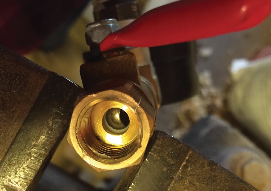
Figure 3. This small reduced-bore ball valve with a PTFE seat, shown here in the half-open position, is similar to the one whose broken stem caused an exhaust-gas scrubber to fail
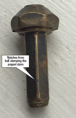
Figure 4. This 1-in. long brass poppet from an unknown source became jammed inside a ball valve in liquid propane service. It stopped the valve closing fully, and so allowed backflow
When exercised, the fill valve felt fine. While the incinerator room was hot, however, the copper pipe remained cold even though the valve was in the closed position. The only way it could be cold was if water was flowing through the “closed” valve. Indeed, the valve stem had snapped, so the fill valve was continuously adding fresh water, cutting off flow to the pre-quench and producing a spray-dried salt fume from the recycled salt water. A $15 valve swap-out solved the problem.
Stuck fuel valve creates inadvertent bypass. A second example of valve troubleshooting relates to the supply of liquid propane to two burners rated at 200 million Btu/h. The two positive-displacement pumps mounted in series produced less than the expected 250 psig output pressure. The first clue was that one pump was noisy, sounding like it was grinding rocks, while the other was comparably quiet.
The liquid propane system contained multiple quarter-turn ball valves. We made sure that those valves that could cause reverse flow and loss of pressure were all closed, and exercised them to verify their operation. All felt good except one 2-in. valve, which gave less than a solid “thunk” when closing. It did not feel quite right, and closed perhaps three degrees short of a full 90-deg swing. With these auditory and touch clues leading the way, the system was vented and the valve dismantled. A brass poppet, perhaps from a pressure control device, was found stuck inside the valve body, keeping it from full closure (Figure 4). With the foreign object extracted, the valve closed and backflow stopped. The pumps — quietly — shared the load and produced the full pressure.
Finding leaks
Leakage in and out of systems is the bane of engineers’ existence, and must be minimized and eliminated. There are many ways of finding leaks, including modern ones like handheld ultrasonic leak detectors. Basic methods still hard at work, however, include soap and water solution (still required by many codes for commissioning fuel gas piping), and using your eyes, nose and ears as a guide.
Air leakage in a thermal soil-treatment plant. A client had a low production rate on a contaminated-soil treatment project in Siberia. The system had a direct-fired rotary dryer/desorber and afterburner. The first step was to get some hard data. A quick test showed 18% oxygen in the stack gas, compared to the expected value of around 7% for a tight system. Checking oxygen levels between the units pinpointed the major air leaks. Eyeballing the system found some access doors open and a shroud missing. In essence, they were heating the surrounding air rather than the process. After closing open hatches, adding some sheet metal and a bit of welding to keep out the frosty Siberian air, production went from 9 ton/h to 16–17 ton/h.
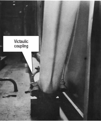
Figure 5. The gasket on a Victaulic coupling on this pneumatic conveying line was cut by embedded chips of concrete, causing it to leak
Commissioning a pneumatic conveying loop. While working as a freshly minted engineer at Particulate Solid Research in New York City, one of us designed and built a pneumatic conveyor system for industrial research, made from 200 ft of Plexiglas pipe with an inside diameter of 4 in. It was instrumented with pressure taps every five feet. During commissioning, the goal was zero leakage.
The leak test method used a simple tool: a rotameter. Both ends of the conveyor pipe were capped off, and compressed air was added via a pressure regulator through the rotameter, slowly raising the pressure as leaks were found and sealed. The rotameter reading provided visual feedback on the size of the leak (for instance, an open valve, a missing pressure tap plug, or weld porosity).
Once the big leaks were found and fixed, a persistent low-level leak remained. The technicians used soap and water to check multiple Victaulic couplings used on the Plexiglas piping, the threads on pressure taps, and the valve stems — to no avail. A change in personnel and sheer persistence eventually located the felonious fitting: a Victaulic coupling in a downcomer just below a penthouse floor (Figure 5) [3]. The coupling’s donut-like rubber gasket carried concrete chips that sliced up the rubber. With a fresh gasket, leakage fell to effectively zero. A final safety note: the compressed air approach is not acceptable for leak-testing at high pressures or large volumes, due to the amount of stored energy in these cases.
Preventing bypassing
Close cousins of leaks are bypassing problems, in which gases, liquids or solids go unexpected places inside a system. One example concerns a transportable high-temperature incinerator that processed soil contaminated with coal-tar creosote. When stack tests were run on the incinerator, two runs passed the required 99.99% lower limit for creosote destruction efficiency by a wide margin. The third test, however, showed far worse results. Interviewing the operators revealed that the failed run was “less stable” than the other two. After further consideration, the operators zeroed in on the symptom that, on that run, the draft in the kiln was not stable.
The hot solids from the 7.5 ft × 45 ft kiln exited to a rotary cooler, with the exhaust gas from the cooler being ducted to a baghouse. This exhaust should have contained only steam, air and dust. However, when the draft was momentarily unstable, CO2 was detected in the duct as well. This confirmed that incompletely oxidized creosote vapors could bypass the oxidizer along with the CO2. The fix was to reroute the cooler fume duct to the oxidizer inlet, thereby fully treating the fume (Figure 6).
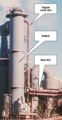
Figure 6. On this thermal oxidizer, under some draft conditions, incompletely treated vapors could be discharged to the stack
Upstream problems
If you don’t look, you don’t see, and if you don’t go inside, all you have is speculation. Sometimes you have to follow the process upstream to find the source of the problem.
Ionizing wet scrubber. An incinerator stack test showed particulate emissions at about 60% over the permitted limit. Upstream was a rotary kiln and a large multi-burner oxidizer. After a pre-quench and acid gas absorber, the fume from the afterburner passed through a single-stage ionizing wet scrubber (IWS), also known as a wet electrostatic precipitator (ESP). The fume passed between grounded parallel plates, with positive charging wires between them. The charged particles would be pulled to the plates by electrostatic forces, and collected on downstream packing.
A properly set-up IWS does a very good job, removing about 84% of almost all particle types per stage. This one was not doing so. In terms of hard data, a visual examination of the M5 test filter paper showed a heavy dust coating, as expected. No news there. The high-voltage power supply showed inconsistent readings of maximum voltage, which were also lower than expected. This was the first clue, since higher voltages means better particle removal. It was time to get dirty.
Upon opening the IWS, we found thick, black, rubbery material here and there on the grounded plates. It looked much like smears of silicone rubber caulk, but with a softer, sludgier consistency. Since the plates were backwashed frequently, they should have been clean, and so the buildup was unexpected. The plate spacing was about 2 in. The buildup, which was up to¼-in. thick, reduced the clearance between the charging wires and the grounded plates, so that short-circuits would occur at lower voltages. So we had found the cause of the low voltage and hence poor collection efficiency. But what caused the black buildup? Time to get dirty again.
Suited up, we entered the large secondary incineration chamber. We expected to see the usual white to brown refractory walls, but instead found walls that were nearly black. Walking up to the burners, we found that the large pilot burner used for startup was missing its refractory tile, whose purpose is to shape the flame and provide a point for flame attachment. Without the tile, the burner would produce a low-velocity, poorly mixed flame, atomizing the fuel but not fully burning it. Oil droplets would therefore bypass the flame and foul the IWS.
The burner tile was replaced, the scrubber cleaned up, and the power supply retuned. A subsequent stack test showed particulate emissions at half the permitted limit.
A contributing issue was probably that the pilot burner was fueled with heavy No. 6 oil, whereas easier-to-burn No. 2 oil would have made more sense for cold startup. In retrospect, it would also have been a good idea to have a sight glass on the oxidizer. This would have allowed operators to see the smoking burner before it caused problems downstream.

Figure 7. Be willing to get dirty for confined space entry inspections
Air-pollution-control system. A large rod bed scrubber (a variation on a venturi wet scrubber) was used to clean up combustion products downstream of a big wood-fired boiler. Unfortunately, this one was allowing more particulates than expected to escape the stack.
Suiting up (Figure 7) and looking inside revealed a buildup of particulate solids on the rod bed. We needed to head back upstream, toward the boiler, to see what might be causing the issue. The plant allowed a two-hour shutdown to gain access. A hole was cut in the steel duct, and in full harness, one of us shimmied in and slid down a 45-deg slope to check the 3,500-hp induced-draft fan. All seemed well there, but looking up into the blackness of the duct heading to the scrubber, things did not add up. There should have been three sub-ducts, separated by welded steel dividers 4-ft tall and¼-in. thick. However, one divider had ripped loose and closed off the other two openings. As a result, almost all the flow was going into a third of the scrubber, overwhelming the water sprays and leading to buildup. There were warning signs: someone had heard a banging noise in the duct a month before, and a patch had been fitted to the high-velocity channel side due to erosion.
More missing burner tiles. An indirect-fired dryer — a three-shell, triple-pass design — had a production rate that was lower than expected. Checking burner condition is always on the list when this happens, since less heat means less driving force for drying. In addition, it is always a good idea to eyeball burners from the business end during shutdowns.
Donning safety gear and crawling along 60 ft of shell, with a tight 18-in. clearance, was made more interesting by the 9-in. flow-inducing baffles rising from below like sharks’ fins and hanging from above like stalactites. Along the way, we found pieces of something — not quite metal, not quite ceramic — in the otherwise clean shell. We were rewarded at the end of the crawl, for two of the eight burners had lost their silicon-carbide tiles. Without the flame shaping and means of attaching the flame that the tiles provide, the burners had been spraying fuel oil on the inner shell, rather than burning it as planned.
Chemistry 101
Mother Nature has a wide variety of chemicals. Some are good, and some not so good.
Scrubber plugging. A client’s acid-gas-absorber packing fouled and plugged, requiring twice-yearly shutdowns. We put a sample of the fouled packing in a beaker of hydrochloric acid. It fizzed and bubbled as expected, and the buildup disappeared. The buildup was a carbonate, which the acid dissolved. A simple acid wash once a year was all the scrubber needed to keep it happy.
Water in your tank. A client suffered plant shutdowns soon after filling their 15,000-gal liquid-propane tank. Restart was never a problem. The seeming randomness of the shutdowns made it hard to zero in on the problem. While we were observing the offloading of propane, however, within five minutes of the truck-mounted pump starting, the plant shut down due to burner loss.
Noticing some icing on the outside of a throttling valve on one of the big burners, we did some digging into issues with propane-fired systems. It turns out that propane can contain water, the amount varying with the source of the propane, the location, and perhaps the time of year. Water has twice the density of liquid propane, so it was lying in the bottom of the tanker and passing into the storage tank when the truck pump started. The water then passed straight into the plant intake below the tank fill pipe, and from there to the burner. When the water caused the flame to flicker, the flame monitoring system cut out the burner.
The solution was more chemistry: adding alcohol to absorb the water and allow it to dissolve in the propane. Being a Sunday afternoon, alcohol supply options were slim. The quick fix was to buy two cases of an alcohol-based winter gasoline additive used to stop water from freezing in automobile fuel lines.
When the next tanker came in, we poured about a gallon of alcohol into the transfer hose, clamped it up, slowly opened the valves, waited, bump-started the pump once, waited, bumped it again, waited, and then pumped the load out. The plant happily hummed along. We got more alcohol in quarts from a truck stop (thanks to one of the operators who knew that it is used for truck brakes), and later a full barrel with a manual pump. With that, the problem was behind us.
Electrical issues
Power is critical to making a plant run, from the three-phase 460 V that powers motors all the way down to milliamp circuits for instrumentation. A multimeter and clamp-on ammeter come in handy when troubleshooting, but as always, people can be even more important than tools.
Pinched wire. A fuel supply pump would shut down randomly, and similarly refused to start on a random basis. The problem had gone on for a while and was growing worse, shutting down an entire plant. We worked with the electricians, who raised the motor amp trip level and changed out breakers, but with no success. The problem appeared to lie between the motor control center and the motor itself. Then the human factor took the stage. When the electrician was told we had to re-pull 500 ft of wire, his brain sprang into action. He said he knew where to look, and found a pinched wire in the cast-steel connection box on the motor. The cover had clamped the wire. A close look at Figure 8 shows where some of the copper has melted from repeated arcing. With wires trimmed back and packed in appropriately, the pump motor — and the client — were happy again.
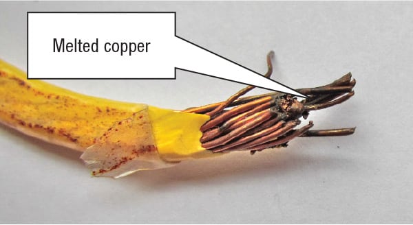
Figure 8. This electrical wire shows melting and arcing at the point where it was pinched inside a connection box, causing an intermittent fault
A bad switch. Switches are a bit like valves. Normally they are dependable, but infrequently they can turn out to be malefactors.
A radioactive hazardous-waste lagoon was being solidified with a grout mixture. A diesel pump transferred the mixture to a 12-ft diameter pond mixer mounted on a 100-ton crane.
The job safety plan called for work to cease during thunderstorms. When the first storm came in, the crew came out. When they went back to work, they found that the idling diesel pump had shut itself down and would not restart. The starter was pulled and replaced, and all was well until the next storm, when the same thing happened. Yet another storm-related shutdown later, it was time to invoke a basic rule of troubleshooting: the third time a problem happens, it’s time to find the root cause and fix the problem.
When we inspected the starter personally, we found that the Bendix-type starter pinion was locked up and the matching ring gear on the engine looked unhappy. The control panel looked like one on a working boat, with switches on a pulpit exposed to the elements. We removed the toggle-type start switch and turned it upside down. Water dripped out. The root cause turned out to be the fact that when it rained, this switch shorted out, and energized the starter motor. The starter got tired of running its Bendix unit into the already turning ring gear, effectively braking the engine to a stop. One marine waterproof switch later, all was well.
The wrong thermocouples. It’s a good habit to specify all the thermocouples on a system to be of the same type. This reduces the chance of a Type R being installed in place of a Type K, and so on. Much mischief has occurred when the wrong type is installed: in incinerators, for example, low oxidizer temperatures and high CO emissions. For very hot equipment, refractory color provides a first approximation to cross-check with control-room readings. The best way to check out the issue, however, is to insert a field thermocouple into a nearby port and compare its readings with those of the installed instrument. When bench-checking thermocouples, one can vigorously stir the tip in a mix of chopped ice and water. If it reads within 2°F of 32°F (or 1°C of 0°C), the thermocouple and its wiring are okay. Another good check for high limits is to pull the high-limit thermocouple and use a propane torch on it.
Uncooperative machinery
It’s been said that machines run better when one of the authors is around, but that is not always the case, as you will see below.
Apron feeder. A rotary kiln system had a slow-moving apron feeder for metering the contaminated soil feed. It stopped feeding during a stack test, which is not a great time for a breakdown. From this point on, the worm-drive gearbox would work only when not under load. Procuring and installing a new gearbox would result in a three-day shutdown.
It’s okay to open things up if they don’t work anyway. With nothing to lose, we therefore had the case pulled apart. Other people who looked at it said that the big 12-in. diameter driven gear was worn out, since it had a groove cut through the outer edge of the teeth. We said otherwise; having read an article on a failed elevator drive of the same type, we knew the groove was part of the original machining, being the root of the worm drive gear. We had the big gear pulled out, knocked off the bearings, and discovered a hidden 3/8-in. square key that had sheared. After a quick trip to the local automotive machine shop that had a hydraulic press, a new key was installed and we were back up and running in four hours.
But what had caused the key to shear? The root cause that killed the gearbox was soil compacting and locking up on the sides of the apron feeder. This is an old problem in bulk solids, which in general are prone to arching and bridging if the length of the flow channel is more than about three times the width. After figuring out the cause, we loaded the belt to no more than 12-in. deep. A mirror above the feed bin, plus a light, allowed the front-end loader operators to see the soil level, and fixed the problem.
Belt conveyor. On the same rotary kiln system, contaminated soil was screened to 2 in. and passed through a dryer, before being transferred to the kiln via a belt conveyor 100 ft long. While walking the circuit during startup, we observed that feed was going into the dryer, but not coming out the other end. The cause was a stick, 2-ft long and about 1.5 in. in diameter, that had made it through the 2-in. screen. Jammed at the feed end of the belt, the stick was pinching the belt edge and backing up soil into the dryer. We alerted the operators to shut down the plant before they filled the dryer up.
This abuse had caused the conveyor belt to slack off. When retightened, it refused to track correctly, trying to run up and off the idler rollers. Several hours of work proved futile and we contemplated replacing the belt (with a two-day downtime), figuring it had been stretched beyond repair. Then the human factor saved us. When the night-shift crew came in, one of them, normally a quiet type, spoke up. He pointed out that when the belt was installed, the nuts on the belt splice faced down. They now faced up! While hard to imagine, this meant the belt had completely inverted itself when the stick pinched it at the feed point. We flipped the belt back over and it tracked perfectly. It had just worn itself into a comfortable position and resented being turned over.
Summary
When troubleshooting, keep your eyes open and be observant. Be persistent. Break the problem into parts to quickly isolate the issue. Ask for help. Listen to people. Take good notes as you go, and always, always write up that trip report to close out the job!■
Edited by Charles Butcher
References
1. Tools and Their Uses – an Armed Forces training manual www.maritime.org/doc/pdf/tools.pdf.
2. Voltmeter and Amprobe Instructions www.wikihow.com/Use-a-Multimeter.
3. McGowan, T., “Disperse-Phase Pneumatic Conveying of Glass Beads in a Four-Inch Diameter Plexiglas Loop,” M.S. Thesis, Department of Chemical Engineering, Manhattan College, New York, May, 1974.
Authors
 Thomas F. McGowan is president and founder of TMTS Associates Inc. (399 Pavillion Street, Atlanta, GA 30315; Phone: 404–627–4722; Email: tmtsassociates1000@mindspring.com; Website: www.tmtsassociates.com), a firm that specializes in thermal systems and air-pollution control. Prior to starting the firm in 1998, he was employed by RMT/Four Nines, Envirite, the Georgia Tech Research Institute, and Particulate Solid Research, Inc. McGowan has 40 years of experience in troubleshooting combustion, air pollution control, and solids handling, and received the Chemical Engineering magazine 2010 Award for Personal Achievement. He holds an M.S. ChE from Manhattan College in New York City, and a master’s degree in Industrial Management from Georgia Tech. He is a registered professional engineer (PE).
 Dennis J. Coughlin is an engineering and management consultant, primarily supporting TMTS Associates, Inc. (contact details as above). He serves companies in manufacturing and the chemical process industries, and focuses predominantly on combustion, thermal treatment, air-pollution control, application of alternative fuels, and power generation. He was previously employed by Westinghouse, GTRI, and Lucent Technologies. He held a number of positions at various facilities with Lucent, including director of manufacturing, director of facilities and construction, and manager of global procurement. He has over 40 years of engineering and management experience, and holds a B.S. in industrial engineering from Georgia Tech.
Field troubleshooting requires engineering…
-
Review available documents (piping and instrumentation diagrams, standard operating procedures, cut sheets)
-
Review available data (tests, event logs)
-
Contact vendors or use the internet to get cut sheets and parts lists
-
Have the right equipment with you, and when you don’t, improvise
-
Break the problem into parts and isolate each issue
-
Keep in mind that failure of a new component is frequently the result of its being the wrong component, or improper installation or operation
-
Understand that very few of the problems encountered in process systems are truly random; if something happens more than once, there is a root cause
-
Organize your work with a checklist and data sheet, and document what you have already checked out
-
Change one variable at a time — isolate cause and effects from each change
-
Understand the chemistry of the process as it was designed, but also of any foreign material or unexpected byproducts
-
Run calculations to home in on the issues and prove or deny suspected root causes
-
Get equipment model/serial number/job number nameplate data, by hand or photo
-
Take good notes and always write up a trip report to close out the job
…and the right behaviors
-
Actively engage the operators and maintenance personnel. Ask for their input, and be aware that all personnel have the potential to answer key questions
-
Ask for help — don’t let your pride get in your way
-
Be persistent and unafraid to ask the “stupid” question
-
Ask what happened right before any unpredicted event
-
Call the original equipment designers
-
Call those who installed the system
-
Call those who worked previously with the system
-
Routinely use senses (eyes, ears, nose and touch) in addition to your brains
-
Take photos for later review
-
Write up notes at the end of each day or the beginning of the next day to keep up with the data and spot errors
-
Take action — don’t be afraid to try things out
-
Get out and around the equipment, and be willing to get dirty as you investigate
-
Set aside time to think over information and discuss with others onsite
-
Use the human factor to your advantage; people are a major resource of knowledge