Large petroleum-refining complexes often have dozens of fired heaters, making broad-based competency in this area essential to overall reliability, safety and energy efficiency. Despite industry’s widespread familiarity with fired heaters, they continue to pose significant challenges during initial control-system design and unless properly specified, operated and maintained, fired heaters can hinder good control and reliable operation going forward.
All fuel-gas-fired heaters have basic features in common, but no two applications are exactly the same, and an industry best practice for fuel-gas control has never emerged. Even one of the most basic questions — whether to use fuel-gas-flow control or pressure control — remains open, with little industry guidance available. A helpful approach to move toward industry standardization is to identify the most common and successful practices based on current technology and experience, for use as a design starting point and a reference point.
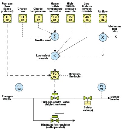
Figure 1 provides a proposed starting or reference point for fuel-gas control-system design for fired heaters. This figure encompasses some areas of judgment and compromise, and not everyone will agree with all aspects of it. In my professional experience, I have found that most sites tend to be strongly disposed toward the local practices they are familiar with. But based on a career of sorting through both new project designs and ongoing operational issues, the findings summarized in Figure 1 provide a high-value starting point, and in many cases a viable finishing point, for the design of many fired-heater, fuel-gas control systems.
Essentially all heater fuel-gas control systems have at their core a heater-outlet temperature controller that is cascaded to either a fuel-gas flow controller or a pressure controller. This is highlighted in Figure 1. All other control components in Figure 1, such as the overrides and feedforwards, are optional and will vary with each heater application, depending on the heater type and performance objectives.
Pressure versus flow control
As API Recommended Practice 556 (API556)* points out, one basic difference between fuel-gas pressure control and flow control is the dynamic response that occurs when adding or removing burners. With flow control, when adding a burner, the pressure will drop, potentially causing a heater trip on low burner pressure. With pressure control, when adding a burner, flow will increase, potentially causing a high- temperature spike.
But this is only half of the story. With flow control, the flow controller will normally restore proper flow in a matter of seconds. Thus, assuming a low-pressure trip is avoided, heater stability is minimally disturbed. But with pressure control, the increase in flow can be substantial, and it is corrected not by the relatively fast pressure controller, but by the relatively slow temperature controller, and this normally takes several minutes. This can introduce a very large temperature excursion, making pressure control highly problematic in applications where operation is near critical metallurgical or process temperature limits, or on processes such as hydrocracking heaters, where the temperature spike could trigger a runaway reaction.
A second area of concern regarding flow versus pressure control has to do with the stability of control during low-firing or startup conditions. The conventional thought is that pressure control is more stable under low firing conditions. For example, API556 suggests that one option is to use pressure control for startup and then switch to flow control after reaching operating conditions. But the quality of modern instrumentation has changed this situation, so today, in most cases, flow control not only performs better at operating conditions, but it is also more stable under low-firing conditions and under load changes and other disturbances.
Traditional instability of flow control during startup or low-firing conditions stems from old-style control valves and orifice-type flowmeters, which are notoriously and inherently unstable under low-flow conditions. Modern high-turndown valve designs with sturdy and precise electronic positioners, combined with high-turndown flowmeters, such as vortex or mass meters, make flow control as stable as pressure control under low firing conditions. Traditional globe-valve and orifice-meter turndown ratios are 3:1, while modern designs achieve 10:1 or even 100:1. And because flow control lends itself to more precise tuning, flow control is arguably more stable than pressure control. Pressure controllers are known to require de-tuning for startup conditions, while flow controllers are not (in the author’s experience).
A third area of performance difference between flow control and pressure control is precision of tuning. Not only is flow control easier and more accurate to tune compared to pressure control, but the temperature controller itself can also be more precisely tuned when using flow control, rather than pressure control, as the cascade secondary control loop. It is straightforward to analyze a historical dataset in a spreadsheet and arrive at a very reliable value for the amount of fuel gas flow that is needed to raise a given heater charge flowrate by a given number of degrees. This provides a nearly perfect gain parameter for the temperature controller (especially if a mass flowmeter is used). The same cannot be said for pressure control, where the amount of flow for a given burner pressure depends upon, among other things, the number of burners currently in service.
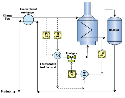
By the same token, flow control lends itself to the accurate application of feedforward, which is effective in eliminating control variance in the heater-outlet temperature caused by changes in the charge rate or temperature. Feedforward is especially effective in breaking the interaction that occurs in many processes, such as hydrotreaters, that have feed-effluent heat exchangers. In this case, the temperature controller is tuned for heater response in the “minute” domain, but the feed-effluent feedback loop can be in the “hour” domain, which often results in large sustained temperature oscillations after an initial disturbance, such as an abrupt change in charge rate or to a more exothermic hydrotreater feed. Figure 2 depicts a hydrotreater process with feedforward control action to eliminate this type of temperature feedback cycle.
The main advantage of pressure control over flow control is that, with pressure control, setpoint limits can be directly configured to help prevent heater trips caused by low- or high-pressure conditions in the burner. This is a potentially important advantage, but overall it probably does not outweigh the several ongoing performance advantages of flow control. A compromise, increasingly popular today as a result of the ongoing emphasis on safety systems, is to use a combination of flow control with pressure overrides. This is also mentioned in API556, but in practice this approach has some drawbacks. In particular, it is inherently hazardous to put a low-pressure override (high selector) on fuel gas. Also, this solution is problematic from a DCS configuration and operational standpoint (see the discussion of “override placement” below). Moreover, a low-pressure override is unnecessary if a minimum fire regulator is used (see “minimum fire” below).
Mass versus volumetric flow
Traditionally, fuel-gas flow is measured with an orifice plate, using volumetric units of standard cubic feet per hour (std. ft3/h). This has also been a traditional limitation, because the heating value of fuel gas commonly varies by as much as 700–1,500 Btu/std. ft3, due to varying amounts of hydrogen and heavier hydrocarbons, such as propane and butane, which often enter the fuel gas system in bursts, sometimes upsetting every heater in the refinery. Many refineries have installed analyzers to monitor fuel-gas heating value to understand the problem, but such analyzers are too slow to be used in actual heater temperature control, so the difficulty has persisted.
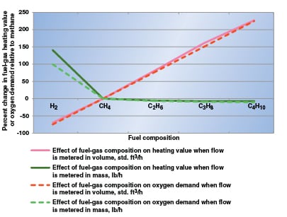
A good solution based on today’s technology is to measure fuel gas flow with a mass flowmeter, such as a Coriolis meter, as mentioned in API556. Modeling fuel gas as a mixture of hydrogen, methane, ethane and propane, Figure 3 illustrates that heating value varies enormously with composition when metered volumetrically, relative to methane. But the heating value is essentially flat for variations in hydrocarbons when metered in mass, although there is still a strong non-linearity due to hydrogen. (Volumetrically speaking, for an ideal gas, atoms of each type are equivalent, while from a mass standpoint, each atom’s heating value is roughly proportional to its molecular weight; hydrogen has a disproportionately high heating value for its small weight.)
The dashed lines in Figure 3 show the effect on oxygen demand (as opposed to heating value). For fuel-to-air ratio limiting, when fuel gas is metered in mass, a single ratio setting can be effective over the full operating range of fuel gas conditions. This complication (the lack of a single valid setting when fuel gas is metered volumetrically) has traditionally limited and usually completely defeated the use of this essential safeguard on balanced or induced-draft heaters. But with mass metering of the fuel gas, a single “set and forget” ratio setting can be employed, resulting in a highly reliable and available safeguard. As Figure 3 shows, where sudden high levels of hydrogen are possible, arriving at an optimum universal setting may still pose a concern, but for variations due to hydrocarbon species and normal or small amounts of hydrogen, mass metering overcomes this traditional limitation to this important safeguard.
Readers should note that limiting the maximum fuel-to-air ratio is the “important half” of full-blown air/fuel cross-limiting, which is common on fired boilers and in the power-generation industry, but is usually considered unnecessary and impractical on simpler fired heaters, and in applications that may have dozens of such heaters, as opposed to a single power boiler.
Overrides (and their placement)
Figure 1 shows three of the most common and high-utility fuel-gas-control overrides. The low-oxygen override responds to fuel-gas flood conditions or potentially to other fuel or air supply faults, depending on the type of heater draft, and is especially important where other excess air controls are absent or may not always be in normal mode. (The low-oxygen override should not be mistaken with excess oxygen control, as this latter option, when used, is applied to air flow or heater draft controls, rather than the fuel-gas controls.) The high-burner-pressure override, like low-pressure protection, is finding increased use due to modern focus on safety systems.
As important as which overrides are employed in each application, is where they are placed, in terms of both the control strategy design and the DCS graphics presentation. For instance, the low-select override in Figure 1 is purposefully placed above the gas flow controller. Moreover, there is no compelling reason to show most overrides, feedforwards, or other control enhancements, on the Level 2 (operating) DCS graphic. In this way, the core concept of temperature cascaded to flow remains intuitive on the DCS graphic and operators see clearly how to take direct control of the valve when necessary, without the need for heater-specific training or the potential for mis-operation. The override setpoints can be connected to their alarm or alert settings so that operators are informed whenever an override becomes active, and to navigate to the Level 3 (detail) heater display, which would include the full control strategy representation, similar to Figure 1 or Figure 2.
The use of a framework such as this — in terms of appropriate override placement within the control strategy design and DCS graphics presentation — is often missing, but it is a much-needed industry best practice. Current habits across industry tend to be much more random, often to the point of creating potential hazards. What happens too often is that overrides are placed below the base-layer controller, or some are placed above and others below, and all are shown in careless arrangement on the DCS graphic. For the operator, this can result in a confusing puzzle that is prone to misunderstanding and mis-operation, rather than as an intuitively obvious heater-temperature-control standard practice. Operator interviews during heater-incident investigations frequently reveal feedback about such “confusing” control configurations and graphics.
The DCS control configuration itself can also create override potential hazards when multiple selectors are introduced into the control design. Correct functionality becomes dependent on a number of DCS configuration parameters that historically are unsecured — that is, are not addressed in management-of-change procedures and may be routinely changed by control engineers or even operators. Not only does this present the DCS console operator with an array of choices for taking direct control of the fuel-gas valve, but each choice may function differently (or not at all) depending on the current state of the others. This also creates a hazardous situation. Intuitively obvious and operable controls should be a high-priority criteria in any control design, especially something as critical as fuel-gas control for fired heaters.
Preventing burner trips
In Figure 1, the minimum-fire self-operated regulator should not be mistaken with the past practice of installing a restriction orifice around the control valve to provide the right amount of stable flow for initial burner light-off, although the regulator does serve this purpose, as well as two others, in a simple and reliable manner.
The minimum-fire regulator also protects against trips resulting from low burner pressure, by having a setting slightly above the trip threshold. This replaces the need for a low-pressure override control and its attendant problems, while at the same time physically limiting the amount of flow the regulator could potentially deliver in the event of regulator failure (in addition to the pressure setting, the regulator orifice size and maximum flow are sized similarly to the traditional restriction orifice). Optionally, the minimum-fire regulator can be supplied by natural gas, rather than by fuel gas, to assure clean and reliable operation This concern is mentioned in API556. It is also worth noting that under ongoing operation, the regulator will remain fully closed, so that relatively expensive natural gas is not continuously consumed.
A third purpose of the regulator is to facilitate easy implementation of minimum-fire trip logic. Minimum-fire trip logic is initiated when process heat needs to be removed, but there is no integrity issue with the heater itself. By tripping to minimum fire, rather than completely tripping the heater, burners will be maintained and restarting is greatly simplified. This can have substantial economic and safety benefits and is a widely under-utilized technique in industry to avoid full heater trips. With a minimum-fire regulator in place, tripping to minimum fire is easily accomplished by soft-tripping the control valve, which is a built-in function in most of today’s DCS control systems. n
* API Recommended Practice 556, Instrumentation, Control, and Protective Systems for Gas Fired Heaters, American Petroleum Inst., Second Ed., April 2011.
Author

Allan Kern is founder of, and principal consultant with, APC Performance LLC (Email: Allan.Kern@ APCperformance.com). He has 35 years of process control experience and has authored numerous papers on topics ranging from field instrumentation, safety systems and loop tuning, to multivariable control, inferential control and expert systems, always with emphasis on practical solutions and effectiveness in a plant operation context. Kern is the inventor of XMCTM, a model-less multivariable control and optimization solution technology. He holds professional engineering licenses in control systems and chemical engineering, is a senior member of ISA, and is a graduate of the University of Wyoming.