Consolidating multiple flares can help mitigate emissions and maintenance
Chris Ng and Zubin Kumana
Siemens, Process Safety Consulting

istock.com/hhakim
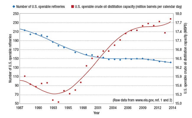
Many petroleum-refining and petrochemical facilities have experienced tremendous growth in recent years in response to increasing demand for fuels and chemical precursors. Due to environmental regulations and economic considerations, it is frequently more desirable to increase the throughput on an existing facility rather than to build a new plant. As shown in Figure 1, the total crude-oil processing capacity in the U.S. has increased steadily as the number of operable refineries declined over the years [1, 2]. The expansion of these facilities has typically resulted in an array of independent flare systems built to meet the requirements of specific expansion projects.
Flare consolidation is one attractive solution that is based on a holistic approach to updating the existing infrastructure to meet growing demands. Integrating separate flare systems into a single flare network can be an economically and environmentally viable solution to meet challenging operational and regulatory requirements.
The benefits
Generally speaking, independent flare systems could be integrated through the installation of crossover piping “jumpers” at appropriate location(s) between the main lines or headers of two existing systems. The rationale and engineering requirements for these modifications are described below.
Though many factors can affect the sizing of flare systems and relief headers, it is usually a type of utility failure, such as total or partial power failure or a loss of cooling water flow, that dictates the design basis of the disposal system. In most petroleum refineries, either partial power failure or cooling water failure is typically the controlling scenario.
Such events are generally localized to a particular area of the plant. For instance, if a chemical facility has three independent cooling-water systems, the loss of any one system should not result in releases throughout the entire facility.
Thus, the availability of a plant-wide flare system can provide increased relief capacity for such scenarios to support the expansion of processing capacity. Since safe operating limits can be set by relief- and flare-system capacities, a well-implemented flare consolidation may lead to an increase in the plant capacity through modest upgrades to debottleneck the flare systems.
Ease of maintenance
With a single large network of multiple flare systems servicing an entire facility, some of the system capacity gained may allow for any one of the multiple flares to be removed from service for maintenance without significantly impacting the operation of the facility.
With independent flares, flare maintenance would require a planned shutdown of the affected units; whereas emergency flare maintenance would require either an unplanned shutdown or turndown of a portion of the plant. In both cases, production would likely be curtailed and would thereby result in higher overall costs.
The ability to perform emergency or scheduled maintenance on the flare system with minimal impact on operations could lead to a significant increase in overall up-time for many facilities.
EPA requirements
The U.S. Environmental Protection Agency (EPA; Washington, D.C.) has released a “National Petroleum Refinery Initiative” to encourage refiners to make a commitment to emission reductions. Since 2000, 109 refineries in 32 states and comprising over 90% of the total U.S. refining capacity have agreed to comply [3]. As part of this initiative, a covered facility may not emit more than 500 lb of sulfur dioxide in a 24-h period during non-emergency situations, based on Emergency Planning and Community Right-to-Know Act (EPCRA) Section 304.
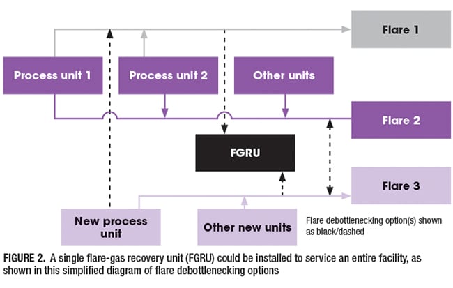
One option to minimize emissions is to install a flare-gas recovery unit (FGRU) for each flare system. The consolidation of multiple flare systems into a single flare network could significantly reduce the cost of compliance as a single FGRU unit could be installed to service the entire facility (or two FGRUs could be installed to improve availability). A simplified diagram of flare debottlenecking options using this approach is shown in Figure 2. In addition, consumption rates of various utilities, such as air, steam or fuel gas to support normal flare operations, could be reduced if a cascaded or staggered flare arrangement was adopted.
OSHA’s PSM standard
The consolidation of multiple flare systems into a single integrated network requires a thorough understanding of the design basis for the flare systems. There is no reasonable means of combining multiple independent systems without a concrete and well-documented design basis for the flare systems, which in turn is part of the process safety information requirement per the Process Safety Management (PSM) Standard 29 CFR 1910.119(d)(3)(i)(D) [4] of the U.S. Occupational Safety and Health Admin. (OSHA; Washington, D.C.).
Methodologies
All credible flare loads should be considered to ensure that the modified system can safely, economically and efficiently handle the expected loads. It is also necessary to understand the current layout of the flare system to optimize flare header connections. A thorough understanding of the current system and the proposed changes allows the designer to confirm that the modified system can operate safely and to validate that flare maintenance requirements can be met.
Identify and document
All potential loads to the flare system must be analyzed and documented. The loads can originate from a variety of sources (such as relief valves, control valves, bleeder valves, emergency shutdown [ESD] systems and so on) and can enter the flare system due to a variety of causes. To ensure that the system is adequately sized, all emergency loads (due to area fires, power failures, cooling water failures and major equipment failures) must be considered, documented, and evaluated. To properly size the FGRU and isolation seal drums for compliance with the EPA requirements, releases during routine operations and maintenance must also be accounted for and documented.
Develop a model
Evaluation of the location of the existing flare headers on a plot plan or other facility map will allow for a quick overview of the system connections and aid in the design of proposed crossovers. Once the consolidated flare system has been developed, a hydraulic model of this flare network can be developed to verify that it can handle the expected loads adequately. Three types of modeling will be necessary: emergency load, non-emergency load and maintenance load.
Emergency load modeling. A standard method, such as the one outlined in American Petroleum Institute (API) Standard 521 [ 5], is applied to ensure that the system can handle the expected emergency loads. Critical items to verify include the following:
1. Backpressure limits — To ensure that the relief capacities for individual sources will remain adequate despite the pressures built-up in the disposal system
2. Header velocities — To ensure that there are no localized areas of high velocity in the flare network that could cause mechanical problems due to excessive momentum forces or acoustically induced vibrations
3. Flare equipment sizing — To ensure satisfactory performance of all relevant flare equipment, such as liquid knockout pots (for vapor-liquid separation), flare seals (including seal height evaluation), flare tip performance (in terms of flare radiation, noise, flame stability and so on), vaporizers and heaters and more
4. Mechanical limits of the header — To ensure that the flare header itself can adequately handle the expected operating requirements
5. Liquid removal facilities — To ensure that the integrated flare loads will not result in excessive mechanical stress due to undesirable flow patterns (such as high-velocity liquid slugs)
Non-Emergency load modeling. All releases to the flare system during normal operation or routine maintenance of the facility should be accounted for. Critical items to verify include the following:
1. FGRU — To ensure that the normal flare loads from all sources — such as leaking relief valves or normally open vent lines plus intermittent releases during maintenance (equipment blowdown), and operations (backpressure control valves, startup/shutdown requirements, purging) — can be handled by the FGRU. This information is used to generate the sizing parameters for the FGRU (especially the compressor).
2. Seal drums — To ensure that excessive or insufficient pressure will not disrupt the liquid seal in the seal drum and result in unintended release from a flare stack during normal operations. Consideration must also be given to ensure that the sealing fluid does not freeze.
3. Liquid knockout — While most FGRU compressors can handle limited liquid on the inlet, large liquid flow to these compressors should be avoided.
Maintenance load modeling. Evaluation of both emergency and non-emergency loads to ensure that all of the established limits would not be exceeded and that the facility could be operated safely should an individual flare (or portion of the header) be removed from service for maintenance reasons.
The results of this modeling could lead to the modification of the consolidated header design or flare operation in areas where facility upgrades are planned. The changes may include the allocation of larger diameter headers, adding mechanical supports, modifying relief devices or flare equipment, adding process safety systems, implementing operational changes, training and so on.
The flow distribution and flow pattern of the flare loads throughout the integrated flare system must be evaluated, because consolidating flares could result in areas of increased corrosion or erosion rates, temperature-induced embrittlement, mixing of chemically incompatible fluids, or a host of other operational or safety concerns.
Fluids follow the path of least resistance. Sizing a flare header that is too large could result in overloading one flare stack in a consolidated system even though the total system may have sufficient capacity. Additional modeling, such as Flare Quantitative Risk Assessment (QRA) may be required to account for the time dependency of flare loads or the statistical probability of various emergency scenarios.
Other design considerations
While the multiple benefits of flare consolidation have been described above, other design considerations could preclude its implementation. In particular, segregation of relief streams could be necessary due to incompatible functional requirements in terms of operating pressure, temperature, fluid composition, or physical properties of the relief streams. Issues such as corrosion, toxicity, reactivity, phase change, and flow pattern of the combined relief streams upon flare consolidation should be evaluated.
Concluding remarks
While flare consolidation may be driven by environmental or regulatory considerations, a properly consolidated flare could provide additional flare capacity, improve operational flexibility, and result in operational savings for the whole facility.
Multiple independent flare systems are not always practical, and there may be more than one option to eliminate the need for flare consolidation. However, performing flare maintenance only during unit shutdowns or turnarounds, installing a dedicated FGRU for each flare, and other options each have their own limitations or drawbacks.
When implemented properly, a flare consolidation program could be an economically attractive solution that allows facilities to maximize the utilization of their disposal systems while maintaining compliance to regulatory requirements of the EPA and OSHA. Sound engineering is required to ensure that environmental impacts and maintenance concerns are not mitigated at the expense of facility safety. ■
Edited by Gerald Ondrey
References
1. Energy Information Agency, www.eia.gov/dnav/pet/hist/ leafhandler.ashx?n=pet&s=mocleus2&f=m
2. Energy Information Agency, www.eia.gov/dnav/pet/hist/ leafhandler.ashx?n=pet&s=8_na_8O0_nus_c&f=a
3. www2.epa.gov/enforcement/petroleum-refinery-national-case-results
4. Process safety management of highly hazardous chemicals, Title 29, Part 1910.119, US Code of Federal Regulations
5. Pressure-relieving and Depressuring Systems, API Standard 521, 6th edition, January 2014
Acknowledgements
The authors would like to thank our Siemens (and old Berwanger) colleagues who have contributed invaluable insights in pressure relief and flare design over the years. This article would not have been possible without their support.
Authors
 Chris Ng is a technical advisor at Siemens, Process Safety Consulting (4615 Southwest Freeway, Suite 900, Houston, TX 77027; Phone: +1-713-570-1204; Email: chris.ng@siemens.com). His expertise includes process design and safety, steady-state and dynamic modeling of multiphase flowlines and process unit operations, process hazard and risk analysis. Ng has executed upstream and downstream design projects for major operating companies. He has a B.S.Ch.E. degree from the University of Western Ontario in Canada, and is a licensed professional engineer in Texas.
 Zubin Kumana is a consultant at Siemens, Process Safety Consulting (same address as above; Email: zubin.kumana@siemens.com). He has a solid understanding of relief device sizing and installation codes and standards, including ASME, API, and Design Institute for Emergency Relief Systems (DIERS), and has performed projects for many of the major domestic and international oil and gas companies. Kumana holds a B.S.Ch.E. degree in from the University of Florida, is a certified project management professional, and is a licensed professional engineer in Texas.