Adding flare-gas recovery units at strategic locations of an olefin plant can not only reduce emissions, but will save money as well
Although gas flaring is necessary at some chemical process industries (CPI) plants or facilities, more and more efforts are underway to reduce flaring, not only to help reduce emissions of air pollutants, noise and light, but also to save both energy and raw materials, which translates into money — potentially millions of dollars.
Today, plant operators are becoming more conscientious about reducing the release of greenhouse gases (GHGs), especially carbon dioxide, in an attempt to prevent further global warming. In some countries, existing or pending regulations on the release of GHGs, or the imposition of carbon taxes are forcing operators to rethink the simple option of gas flaring.
In some cases, however, it can make good economic sense to recover rather than burn the flare gases, which are often valuable hydrocarbons that can be used as fuel or even feedstock. The investment costs for adding a flare-gas recovery unit (FGRU) can thus be offset by utilizing the energy or the resources (or both) recovered by the FGRU. The environment benefits by reducing the volume of flare gases that are actually flared.
In this article, we investigate methods to recover flare gases and thus reduce gas flaring in olefin plants. As an example, the benefits of installing an FGRU after the cold flare drum at an ethylene plant are presented.
The article examines flare-gas recovery methods and the advantages of applying them to olefin plants. The case study presented here concludes that significant amounts of ethylene and fuel gas can be recovered, with corresponding savings of more than a million dollars per hour.
Olefin plants
Olefin units (Figure 1) are among the most profitable plants in the petrochemicals industry. Due to the nature of these units, there is a good potential for using FGRUs during startups to reduce emissions and recover capital. Given the expanding number of olefin units in the world today, with flaring an integral part of the factories, large amounts of energy and capital are lost. Therefore, it makes good sense to consider more deeply the use of FGRUs with such units.
![FIGURE 1. A typical flowsheet for an ethylene plant is shown here [1]](https://www.chemengonline.com/wp-content/uploads/2015/05/16.jpg)
FIGURE 1. A typical flowsheet for an ethylene plant is shown here [1]
Flares and flaring
Flaring is a safe and effective method for the disposal of hydrocarbons in situations where there is an equipment failure or in emergencies, such as instrument failure, power failure or a fire in the plant. Many vapors are corrosive, explosive or flammable and cannot simply be released into the atmlosphere, so burning them is essential [2–4].
Flares are classified according to different viewpoints, for example in terms of the following:
- Height — elevated (according to the support, which can be self supported, guyed wire, derrick) and ground flares
- Assisted fluid for smokeless operation — steam-assisted or air-assisted flares
- Combustion chamber — open, semi-open or closed flares
- Number of tips — multipoint or matrix flares Flare-gas pressure — high-, medium- or low-pressure flares
- Special areas — storage areas or terminals can have dedicated flares
Flaring points in olefin plants
To achieve zero flaring, we must first investigate what are the main reasons for flaring. Activities where flaring is used include plant startups and shutdowns, maintenance procedures, plant upsets and sometimes even normal operation.
Flaring leads to the release of large amounts of CO2, carbon monoxide, oxides of nitrogen (NOx), hydrocarbons and other volatile organic compounds (VOCs) and others. Besides emissions to the atmosphere, simple flaring is a loss of both energy and raw materials.
For instance, an ethylene plant with a production capacity of 1.2 billion lb/yr of ethylene can easily flare about 5 million lb of ethylene during a single startup. Assuming a flaring efficiency of 98%, the resulting air emissions will include at least 15.4 million lb of CO2, 40,000 lb CO, 7,400 lb NOx, 15,100 lb of hydrocarbons and 100,000 lb of VOCs. This is just a normal accounting of ethylene flaring emissions. If all the flaring sources are included, such as ethane, propylene and propane, huge amounts of air emissions can be produced through one single plant startup. By reducing the volume of flare gases, we can also be assured of complete combustion and a smokeless flare.
The main activities at olefin plants that lead to gas flaring are from the following sources:
- Cracked-gas-compressor (CGC) suction: When the compressor is stopped; from the initial startup of furnaces until the furnaces reach their full capacity; and during the commissioning of the compressor
- Chilling train tailgas outlet: When there is a limitation to the fuel-gas system from the demethanizer, additional products will be sent to the flare for plant-safety considerations
- Deethanizer top product: When this stream is not within design specifications for sending to the hydrogenation reactor, there will be flaring in order to prevent catalyst deactivation
- Hydrogenation reactor outlet: A large amount of flaring in an olefin plant occurs at this point. The outlet stream from the reactor will be sent to the flare until the required specifications are achieved. There will also be gas flaring after sending this stream to the C2-splitter tower until the tower reaches the normal operation conditions and liquefaction occurs
- C2-splitter top stream: Until the tower product reaches the required specifications, there will be gas flaring
Flaring may be scheduled or unscheduled. Unscheduled flaring may be caused by a trip. Scheduled (or planned) flaring occurs during shutdowns, maintenance and startups. During a shutdown, the plant feed will usually be decreased to the minimum amount with which the plant is still stable, and the cracking-gas compressor will be out of service. This process will lead to flaring.
Startup is a situation that leads from the initial state of the process to the final operating conditions. During this operation, the feed is gradually increased and equipment will be pressurized, and hot or cold liquids will reach their operating conditions. During these activities, large amounts of gas are directed toward a flare boom.
Unscheduled flaring includes operation failures, equipment failures, electrical failures and so on. When such events occur, the best option to ensure the safety of equipment and personnel is flaring, which is an effective, safe and fast method for handling gases that are generated. For plant trips that lead the unit into a purge condition, activities must be quick and effective to return the unit to normal operating conditions.
Most trips occur with cracked-gas compressors, refrigeration cycle compressors, instrument failure, weather and so on. These trips may cause a partial or total shutdown of a plant. In such circumstances, pipes and equipment are depressurized and the vent streams are sent to the flare until the unit can be returned to normal operating conditions.
We can summarize the following methods that can be used in reducing gas flaring in ethylene plants:
- Define recycle streams for the recovery of off-specification products
- Maintain the amounts in towers by keeping them in total reflux status
- Properly control feed when injecting feed into furnaces, one furnace after another
- Cool the chilling section as quickly as possible to reach the optimum temperatures
- Ensure that conditions are normal before the demethanizer flow is established downstream
- Return high-purity ethylene back into the reflux drum to reduce the settling time in the tower [5–7]
Ethylene plant FGRUs
There are several methods for flare gas recovery, which include the following general categories:
- Physical: The gases are recovered and purified by special equipment and pressurized (if required) for process units to be used as fuel or feedstock
- Chemical: The flare gases are reacted over a catalyst and converted into industrial materials that can be recovered
- Biochemical: This newest method of recovery is performed using bacteria that carry out degradation reactions in the towers, thereby converting the flare gases into simpler components
Regardless of which method is used, the recovery of some or all of the flare gases will decrease combustion products and the release of pollutants into the atmosphere, reduce fuel requirements and minimize flare-tip maintenance, as well as reduce thermal radiation, light, noise and odor. Ultimately, flare-gas recovery leads to increased plant efficiency.
In order to select the most appropriate solution for flare-gas recovery and the reduction of gas flaring, you must have a good understanding of how the flare gases are produced, distributed and best consumed at the production facility.
Designing an FGRU for an ethylene plant is far more complex than designing one for a liquified natural gas (LNG) plant or for petroleum refineries, because the processes and equipment performance at an ethylene plant are highly sensitive to the compositions involved. For example, changes in the heating value of fuel gas fed to the furnace can cause the destruction of the special burners. Composition changes can even cause problems in the pyrolysis process, resulting in a plant shutdown. Therefore, when introducing flare-gas recovery in ethylene plants, one must be very careful to keep the operation of the plant stable and ordered.
There are two physical-separation processes that can be used in olefin FGRUs: membrane separation and adsorption. It should be noted that the use of temperature-swing adsorption (TSA) greatly increases the risk of undesirable olefin polymerization reactions; but with pressure-swing adsorption (PSA), such risks can be avoided.
Figure 2 shows an example of an adsorbent system based on activated carbon (AC) for flare-gas recovery. There, one can see that a stream from the main header from the knockout (KO) drum is directed to the FGRU. This stream is directed to a blower and sent to the absorber system. (The blower prevents any problems that might occur in the flare-gas header).
![FIGURE 2. This flare-gas recovery system is based on beds of activated carbon [8]](https://www.chemengonline.com/wp-content/uploads/2015/05/24.jpg)
FIGURE 2. This flare-gas recovery system is based on beds of activated carbon [8]
The first pair of AC beds are for C5+ recovery and second pair for propylene recovery. The stream leaving the top of the propylene adsorption beds is rich in nitrogen, and is sent to a flare downstream of the KO drum [3, 8].
In addition to adsorption beds (including PSA), membrane-based separation systems can be used for the recovery of propane/propylene and ethylene at the refrigeration cycles charge, with the remaining gases sent to the C3+ storage tank. It is notable that the recovery and reuse of valuable components, such as C2 or C1–C3, from the wet flare (WF) drum to the quench tower is possible and economical (Figure 3). This should be kept in mind during the initial design stage for a new plant, so that the design of the refrigeration cycle can include enough cooling to supply the FGRU. In this way, we can recover valuable gases and reduce emissions form gas flaring.
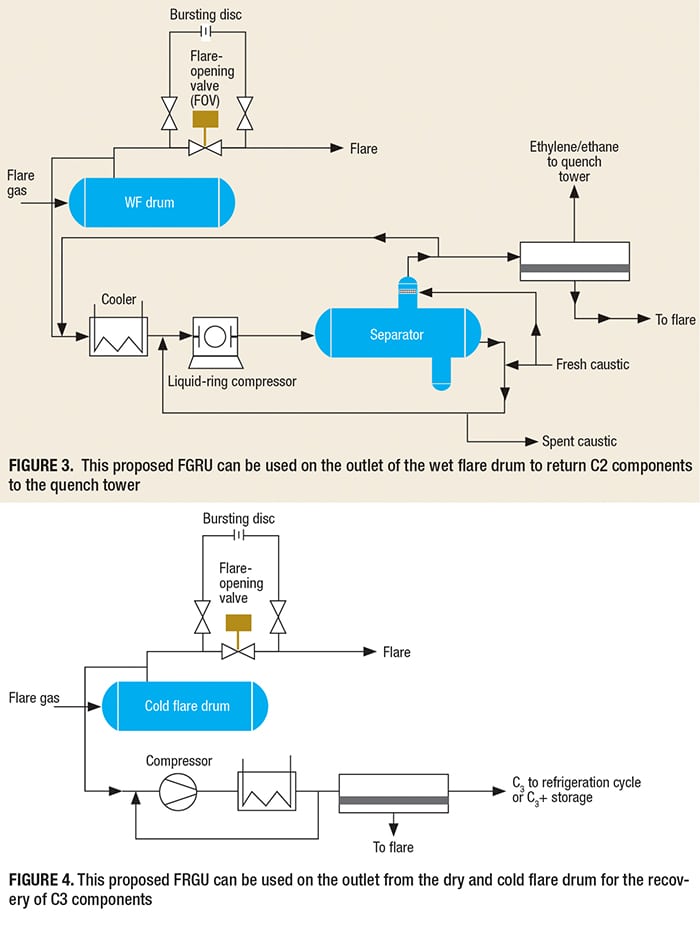
Generally, all of the quench towers in an olefin plant operate in the pressure range of 0.4–0.5 barg. Because caustic is available both for cooling and as the absorbing media, it can be used for operating the liquid-ring compressor in Figure 3.
Additional methods are possible for recovering flare gases from the cold flare drum, as shown in Figures 4 and 5. In these methods, the outlet gas from the cold flare drum are sent to the FGRU using one compressor. Because the gas in this section (cold section) is dry, it is not necessary to use a special compressor, such as a liquid-ring compressor. Another important advantage is that an absorption tower (and regeneration of the absorbing fluid, if using amines) is not required.
Parameters affecting FGRU
The parameters with the strongest influence on the recovery system is the composition of the flare gas. In general, changes in molecular weight in the stream going to the FGRU can create the potential for overloading the compressor, leading to possible damage. Molecular weight changes can also increase the temperature of the gas after compression. The following three compositions have the most notable influence:
- The effect of N2 on heat exchangers and compressor performanceThe effect of H2 and light gas on compressor performance
- The effect of steam on the separation drum, the compressor and membranes
- The temperature of the inlet to the compressor must also be controlled. If the compressor inlet temperature is higher than the design temperature, the gas must be diverted to the flare. It should be pointed out that the capacity of the FGRU is a function of the capacity of the compressor system that is used [9, 10].
Emissions from flaring
In order to compare the emissions of pollutants, noise (acoustical) and thermal radiation for a plant before and after the introduction of a FGRU, one must first be able to calculate these values for the case of flaring only. Simulations were performed using commercial software for a typically sized olefin plant with a flare gas capacity of 90 metric tons per hour (m.t./h), and the results were compared to the same plant that uses the third proposed FGRU shown in Figure 5. The 90-m.t./h value is typical for the startup of an olefin unit that had been shutdown due to a problem in the cold section.
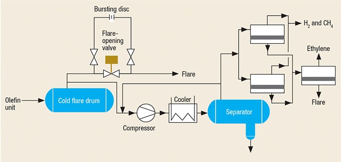
FIGURE 5. The design for a FGRU used on the outlet of the cold flare drum to recover ethylene, methane and fuel gas
The calculations for the simulaton were based on the following equations:
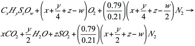
Pollution emissions. In the high-temperature combustion processes, several hundred to several thousand chemical reactions are taking place. Assuming complete combustion, the following general reaction can be used:
 (1)
(1)
Of course, complete combustion is not normally achieved in flares, so there will also be carbon monoxide, NOx and other hydrocarbons released during flaring. A simpler way to calculate the effluent of pollutants during flaring is to use Equations (2):
![]() (2)
(2)
Where:
Q = production rate
Ex = emissions of pollutant x, lb/h
EFx = emission factor of x (from the the U.S. Environmental Protection Agency’s compilation of emission factors, AP-42 [11]
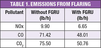 Table 1 shows the results of the calculation for the emissions of NOx, CO and CO2 before and after the installation of a FGRU.
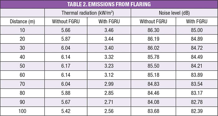
Noise and radiation. The thermal radiation and noise level as a function of distance from the flare can be calculated using commercial software for flare systems. The results of these calculations are presented in Table 2.
It is also possible to make quick estimates of the thermal radiation released during flaring of gases by using Equation (3):
![]() (3)
(3)
Where:
Q = production rate
H = heating value
V = volume of gas
A simple calculation for noise emissions can also be performed using Equation (4), which is based on the VDI 3732 Guidelines for an elevated flare [12]:
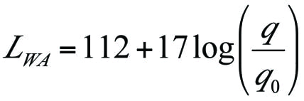 ( 4)
( 4)
Where
L WA = weighted average sound power of the total noise emitted, dB
q = gas mass flowrate, ton/h
q0 = reference mass flowrate, ton/h
For a flare that burns a gas stream of 90 m.t./h with a heat of combustion of 2,390 kJ/kg, Equations (3) and (4) give 59,800 kJ/s or about 60 MW of power released by the flare. This value drops to about 40 MW with the introduction of a FGRU that reduces the volume of gas flared by about 40% (35.9 m.t./h).
For the same 40% reduction in flare gas being flared, Equation (4) shows a reduction in sound emissions by about 6.8 dB.
Payback
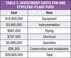 Table 3 shows that the total investment costs for the FGRU proposed in Figure 5, which is capable of handling a flare-gas stream of 90 m.t./h, is about $30 million [13, 14].
Based on the installation of such a FGRU after the cold flare drum, we have calculated that 43.3 m.t./h of ethylene and 10.8 m.t./h of fuel gas can be recovered and returned to the olefin plant. The value of the recovered gases is roughly equivalent to about $52,000/h.
According to monitoring studies, this olefin plant has about 185 hours of flaring per year during planned or unplanned shutdowns. This means that about $9 million/yr of valuable gases are returned to the plant and the investment costs are recovered after about three years of operation of the FGRU. The environmental benefits of reduced emissions of pollutants, noise and thermal radiation are an added bonus. ■
Edited by Gerald Ondrey
Acknowledgment
The authors would like to thank Najem Beg and Sacha Sarshar from Caltec Co., and Gholamreza Jokar and Shapour Taghipour from Morvarid Petrochemical Plant for their support and guidance.
Refrences
1. Process Analytics in Ethylene Production Plants, Oil & Gas Industry, 2007.
2. Ghadyanlou, F., Flare Design, 1st ed., Andishesara Publishing Co., March, 2011.
3. Shahini, M.,Flare Gas Management, Jahanno Publishing Co., 2th Ed., March 2011.
4. Baukal, C.E. and Schwartz, R. E., The John zink Combustion Handbook, 1st ed., CRC Press,March 27, 2001.
5. Falaqi, F. H., “The Miracle of Petrochemicals-Olefin Industry: An In-Depth Look at Steam Crackers, Universal Publishers, Fla., 2009.
6. Liu, C., and Xu, Q., Emission Source Characterization for Proactive Flare Minimization during Ethylene Plant Start-ups, Ind. Eng. Chem. Res., 49, 2010, pp. 5,734–5,741.
7. Yang, X, Xu, Q. and Li, K., Flare Minimization Strategy for Ethylene Plants, Chem. Eng. Technology, 33, No. 7, 2010, pp. 1,059–1,065.
8. Page, J. E., Reduction of Hydrocarbon Losses to Flare Systems,1st Industry Technology Conference, Houston, April 22–25,1979.
9. Zadakbar, O., Vatani, A. and Karimpour, K. Flare Gas Recovery in Oil and Gas Refineries, Oil and Gas Science and Technology, Rev. IFP, Vol. 63, No. 6, 2008, pp. 705–711.
10. Blanton, R. E., Environmentally and Economically Benefical Flare Gas Recovery Projects in Petrochemical Facilities, National Petroleum Refiner’s Assn. Environmental Conference West, San Antonio, Tex., September 2010.
11. AP-42, Compilation of Air Pollutant Emission Factors, 5th ed., U.S. Environmental Protection Agency, Washington, D.C., www.epa.gov/ttnchie1/ap42.
12. VDI 3732 – Characteristic Noise Emissions Values of Technical Sound Sources – Flares, VDI Guideline, Verein Deutscher Ingenieure, Düsseldorf, Germany, 1990.
13. Trambouze, P., Petroleum Refining — Material and Equipment, Vol. 4,Technip Editions, Paris, 1994.
14. M. Peters, M., Timmerhaos, K. and West, R. E., Plant Design and Economic for Chemical Engineers, 5th ed., McGraw-Hill Co. New York, December 2002.
Authors
 Farhad Ghadyanlou is the manager of the R&D Dept. of the Morvarid Petrochemical Plant, (Petrochemical Zone No 2, Pars Economical Energy Zone, Assaluyeh, Iran; Phone: +98-772-7293035, Ext: 5086; Email: ghadyanlou@gmail.com). He holds an M.Sc. degree in chemical and environmental engineering from Islamic Azad University, South Branch of Tehran and a B.Sc. in chemical engineering and the gas industries from Islamic Azad University of Omidea (Khuzestan, Iran).
 Ali Vatani is an associate professor in the School of Chemical Engineering, College of Engineering at the University of Tehran (Enghelab Ave., Tehran, Iran; Phone: +98-21- 66461024; Email: avatani@ut.ac.ir). Among the many lecture courses he offers are those dealing with oil-and-gas, petrochemicals, gas processing and distribution and two-phase fluid mechanics He holds B.Sc. and M.Sc. degrees from the University of Tehran, and a Ph.D. from the University of Leeds (U.K.).