Small chemical reactors offer a number of benefits compared to large reactors, such as better heat transfer and mixing. While small batch vessels are impractical at the industrial scale, continuous flow reactors can provide the benefits of small physical size without the practical difficulties of multiple vessels. This article considers the four basic needs of flow reactors (volumetric capacity, heat transfer, plug flow and mixing) and how they influence choice of equipment.
Flow reactors
A small chemical reactor has a higher ratio of heat transfer area to working volume than a large reactor. It can also deliver more mixing energy per unit volume without bending the agitator shaft. Since the outcome of most chemical reactions is linked in some way to mixing or heat transfer (or both), small reactors have inherent advantages over large ones. Depending on the reaction type, these advantages can contribute toward substantially lower capital and operating costs. Small batch vessels, however, are impractical at the industrial scale since hundreds or even thousands of process cycles would be required for commercial throughputs. The solution to this problem is to use a flow reactor. This is a channel or series of mixed stages in which process materials react as they flow through it. It is analogous to a series of small, stirred batch vessels on a conveyor belt. A flow reactor provides the benefits of small physical size without the practical difficulties of charging and emptying multiple small vessels.
Historically, flow reactors have been more common in bulk chemical processes where the problems of vessel size are most acute. With growing pressure on chemical manufacturers to meet ever-tougher cost and regulatory targets however, the range of applications for flow reactors has started to expand rapidly.
Flow reactors are not new technology, but many of the applications they are now being developed for are new, and as such progress is confronted by the usual adoption problems of market resistance, availability of the right equipment and lack of user knowhow.
User knowhow is arguably the biggest hurdle to progress since most engineers and scientists were trained in batch methods and have had little experience with flow technology. While good knowhow does exist, this is still concentrated within a relatively small number of individuals or groups. For the wider industrial community, many basic questions relating to the business case and implementation methods for adopting flow processes fail to get answered properly. For example, the question of energy saving is often dismissed on the grounds that the temperature cycle in a flow reactor is broadly similar to that of a batch reactor and therefore, there is no net energy saving. This, however, disregards the fact that a flow reactor may have many tons less of hardware to heat and cool, and does not require a fivefold oversizing of the utilities to cope with uneven heating and cooling loads. Implementation of flow reactors also remains far too reliant on trial-and-error rather than systematic methods. All too often good applications for flow technology get abandoned during trials for lack of the right equipment or operating methods.
There are difficult challenges for flow reactors, such as fouling and large solids. Apart from these however, flow reactors are easier to scale up than batch systems, since the size differences between laboratory and production scale are greatly reduced. Success, however, is contingent on a good understanding of the underlying process characteristics and a broad knowledge of reactor types to address the specific needs.
Reasons for continuous
The benefits of flow reactors vary according to the nature of the process, but they typically include the following:
• Improved yield and quality — For competitive and consecutive reactions, flow reactors can deliver significant improvements to yield and purity
• Reduced solvent use — For heat-transfer limited reactions, flow reactors can operate with leaner reaction mixtures and therefore with less solvent. Similarly, continuous countercurrent processes for operations, such as extraction, yield better separation with less solvent
• Capital cost — For mixing or heat-transfer limited processes, flow reactors are smaller and often significantly smaller than batch reactors. Smaller physical size contributes to lower equipment costs as well as smaller utilities and buildings. Capital expenditure reductions on building costs alone for a continuous plant can amount to 50% or more [ 1]
• Utility costs — Over 50% of the energy used in a batch reactor is wasted on the hardware, cross mixing between the heating and cooling fluids and uneven utility loads. Flow reactors can reduce this waste by 90% or more by virtue of reduced physical size and steady state operation
• Plant flexibility — Batch reactors have good flexibility in terms of the unit operations they can perform, but very limited flexibility in terms of working capacity. A flow reactor is more specialized in terms of unit operations it can perform, but the capacity per cycle can be varied by orders of magnitude by changing the cycle time. This can contribute to greater plant flexibility and therefore less process equipment
• Safety costs — For hazardous processes, the cost of managing safety in small flow reactors is inherently cheaper than large batch reactors. Small pressure vessels are cheaper to fabricate and require smaller emergency-relief systems
The extent to which these benefits apply depends on factors such as process type, product value and throughput. It also depends on whether the application is for an existing facility or a new one.
Manufacturers from the chemical process industries (CPI) often view the batch versus continuous question as an either/or option, and reject flow reactors on the grounds that the batch vessels are still required for work-up operations. While this may be true in many cases, the commercial advantages of using flow reactors within existing batch processes should not be underestimated. Flow reactors generally occupy small footprints and can be integrated within existing batch plants. Where flow reactors can make a material difference to yield or reduction in batch failures, the commercial case for using them within existing batch processes can be self-evident. There are also other reasons for using flow reactors within existing batch processes, such as debottlenecking, reducing energy waste, more efficient use of solvents, improved safety, reduced problems of bursting disc failure (which can disable an entire production facility) and increasing plant flexibility.
Understanding the process
While microreactors can be used successfully with very little process information, the same does not apply to larger flow reactors. Scaling up flow reactors by trial-and-error is difficult and potentially dangerous. A good understanding of the process is required before trials are undertaken.
A variety of analytical devices can be used to study flow processes, but one of the most useful tools for generating design data is a reaction calorimeter, since this provides information about both kinetics and heat of reaction. It is also worth noting that the differences between batch and flow reactors relate to scale (there is no flow effect) and a small reaction calorimeter with similar heat transfer and mixing characteristics (to the proposed flow reactor) can provide reliable design data for scaleup.
Even where processes are relatively well understood however, there is no substitute for testing under flow conditions. The equipment used for scale-up development should be as similar as possible to the full sized reactor. This generally favors the use of large flow reactors for scaleup work rather than microreactors (other than where microreactors can be used at the production scale).
Reactor capacity
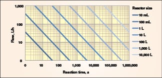
The volumetric capacity of a flow reactor should be as small as possible. Apart from the obvious benefits of small footprint and higher performance, small flow reactors have proportionately lower startup and shutdown losses. The physical size is calculated from the relationship:
Reactor size (L) = Throughput (L/s) × Reaction time (s)
Reactor sizes for a range of throughputs and reaction times are shown in Figure 1.
A flow reactor can be scaled up by a process of numbering up (or scaling out). For this, the channel size is kept constant and capacity is increased by using multiple parallel channels of similar size. The size of the scaled up system can be predicted accurately when numbering up, since the functional capabilities of the channels remain unchanged.
The reactor can also be scaled up by increasing the channel length, although scope for this is limited by pressure drop. In some cases, longer channels will give better performance (due to higher velocities) and therefore require smaller working capacities than predicted.
Increasing the tube diameter is often the only practical way of scaling up, especially where high reactor volumes are required. Increasing the diameter, however, often reduces performance, and therefore the scaled system may have to be larger than predicted to compensate for the difference.
When scaling up, it is preferable to use the maximum tube diameter possible, subject to satisfactory performance. Short, large-diameter tubes have lower fabrication costs, a reduced tendency to block and a lower pressure drop. They are also easier to clean.
Plug flow

Plug flow describes a flow pattern where the fluid velocity across the face of a channel is uniform (Figure 2). It also implies no back mixing and all fluid elements having the same residence time. While plug flow is required for most applications, ideal plug flow cannot be achieved in practice due to the effects of molecular diffusion, surface drag, bends and obstructions in the channel.
Microreactors typically have channel diameters of less than 0.5 mm. In these systems, the plug flow characteristics benefit from low fluid velocities [ 2]. This is a useful characteristic as the reaction time can be varied from less than a second to many minutes in relatively short channels.
In larger diameter channels, good plug-flow characteristics benefit from high fluid velocities [ 2], and the channel length has to be varied to suit the reaction time. Good radial mixing is also desirable to prevent the fluid from separating into zones of fast — and slow — moving fluid. Radial mixing can be achieved by means of baffles, static mixing elements, dynamic mixing and turbulent flow. A good approximation to plug flow can also be achieved by using multiple stirred tanks in series, and the higher the number of tanks used the better. Above ten stages, however, the cost of additional stages starts to outweigh the incremental benefits.
Plug flow is determined by experimental methods such as dye injection tests. These data need to be treated with care, because the quality of plug flow required will change with the reaction rate. The observed quality of plug flow can also change as the physical properties of the fluid changes.
 |
|
Figure 3a. In a plug flow reactor, material is only retained in the reactor
while it is reacting, and it cannot be discharged until the required residence time has elapsed |
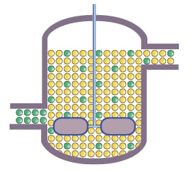 |
| Figure 3b. An example of a system that is not plug flow is the continuously stirred tank reactor (CSTR), which is fully back-mixed. In the absence of plug flow, reacted material is retained for longer than required, and unreacted material is discharged prematurely. It is therefore inherently less efficient than either a plug reactor or an ideal batch reactor |
Plug flow provides the means for separating reacted and unreacted material (Figure 3a). Without plug flow, some product is retained for longer than required in the reactor and some unreacted material is discharged prematurely (Figure 3b). Good plug flow is the key to minimizing reactor size and optimizing yield and purity. A common misconception is that plug flow is not required for zero order reactions (where the reaction rate is independent of reactant concentration). This is not correct. Plug flow is important for virtually all processes, even for zero order reactions. The exception to this is fast zero-order reactions (typically a few seconds or less) where reactor size is not a significant cost issue and there are no consecutive reactions.
For many applications, the benefits of good plug flow are not limited to residence time control. Where the reaction rate is dependent on reactant concentration ( n th order reactions), low back mixing reduces dilution of unreacted material giving faster reaction rates and higher yields per unit volume. Plug flow also provides the means for preventing material from over reacting, and reducing reactions between reactants and product.
Where the outcome of a reaction is particularly sensitive to plug flow, high fluid velocities and long channels are desirable. From the perspective of pressure drop and reactor cost, however, there are practical advantages to minimizing channel length. A good compromise is to use long small-diameter tubes where the reaction rate is high (and therefore more sensitive to back mixing) and larger diameter tubes where the reaction rate is slow.
Mixing
Mixing can be characterized in many ways, such as applied mixing energy, uniformity of mixing, time to achieve a uniform blend, Reynolds number or mass transfer characteristics for two phase mixtures. There are also different mechanisms for promoting mixing, such as molecular diffusion, turbulent flow or splitting and folding of fluid streams. In a flow reactor, the optimum mixing condition is good radial mixing (mixing across the tube) with low axial mixing (mixing along the tube).
Scale is important for mixing. For example, a small flow reactor can blend a fluid in a fraction of a second, whereas a 1,600-L batch reactor can take 10 to 20 seconds [ 3].
Microreactors operate under laminar flow conditions with Reynolds numbers of typically less than one hundred [ 4]. The flow streams are parallel, and these systems rely principally on molecular diffusion for radial mixing. Microreactors have a reputation for good mixing that is not always deserved. For demanding mixing applications, such as with two phase fluids, it is often necessary to employ static mixing elements within the channel to promote radial mixing.
The need for good radial mixing becomes increasingly important as the diameter of a flow reactor is increased. Without radial mixing, large tubes bring problems of poor blending, poor plug flow and reduced heat-transfer performance.
There are two general methods for promoting radial mixing: dynamic mixing and static mixing. In dynamic mixing, mechanical stirrers generate radial mixing. In static mixing, radial mixing is promoted by either turbulent flow or elements that break up the flow pattern (baffles or static mixers).
Mixing is a difficult parameter to characterize, and the mixing conditions can also vary within the channel as the physical properties of the process material changes. For this reason, there is no substitute for testing. Some general considerations for mixing in larger systems include the following:
• Good radial mixing is required throughout large flow reactors even when the process fluid is fully blended in order to maintain good plug flow and where applicable, efficient heat transfer
• For some processes, such as competitive reactions, mixing at the point where reactant streams combine can be essential for optimum performance. For these, different mixing strategies may be required at the inlet and early stages of the reactor
• Processes with more than one phase (solid, liquid, gas) usually have mass transfer limitations. To overcome the limitations, these processes require high mixing efficiencies throughout the reactor to maximize interfacial area- and mass-transfer coefficients
• Where solids are present in the process fluid, efficient mixing is required to keep them uniformly dispersed and free flowing. Dynamically mixed flow reactors have the advantage of keeping solids suspended if the flow is interrupted. In a statically mixed system, an interruption to flow can lead to a serious blockage
• Where the process fluid contains fragile materials, such as crystals or live cells, mixing is constrained by the need to prevent product damage
Heat transfer
In a tubular flow reactor, heat is added or removed by a cooling jacket. The amount of heat that can be transferred per unit volume of product in a tube ( Q v) is determined by the relationship:
Qv = (4 × U × ΔT)/D
The heat transfer coefficient ( U) is typically in the range of 50–1,500 W/m2/C. There is little scope for varying this since the parameters that determine it are fixed by other needs.
The heat transfer rate can be controlled by varying the temperature difference between the process fluid and the heat transfer fluid ( ΔT). This is typically in the range of 0 to 50C, but it can be higher where the process fluid can tolerate extreme surface temperatures.
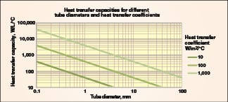
The amount of heat that can be transferred per unit volume of product ( Q) is inversely proportional to tube diameter ( D). This means that the tube diameter needs to be small enough to cope with the process heat load. Cooling capacities for different tube sizes and heat transfer coefficients are shown in Figure 4.
Where the product can tolerate extreme temperatures, heat transfer is not important to design and short large-diameter tubes are preferable for reasons of cost, low pressure drop and ease of cleaning. In such cases, the feed and discharge temperatures can be controlled by separate feed and discharge heat exchangers, respectively. If the process temperature can rise above the normal boiling point, elevated operating pressures are required to suppress boiling. Boiling in a flow reactor is undesirable as it reduces the working volume.
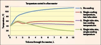
Temperature control. For many processes, good temperature control is necessary and reactor design has to take account of variations in process heat load along the channel. In microreactors, high levels of heat can be added or removed with low temperature differences between the jacket and the process fluid. This means that a single cooling strategy can often be applied without causing serious overcooling where the process heat load is low. In larger flow reactors, higher temperature differences between the jacket and process fluid are necessary to compensate for the lower surface-to-volume ratios. If a single cooling strategy is employed under these conditions, problems of overcooling can arise in areas where the process heat load is low (for example at the end of an n th order reaction). While it is feasible to manage this with co-current flow (between the heat transfer fluid and process fluid), a more practical approach is to treat the channel as a series of stages with different channel sizes or jacket temperatures (to cope with different heat loads). The example shown in Figure 5 illustrates different cooling strategies for an exothermic reaction in a 10-L reactor:
• In the first case, no cooling is applied, and the tube diameter is 38 mm. The overall reactor length is 9 m, and the product temperature rises to over 100C
• In the second case, a single coolant temperature of 0C is used. The first cooling stage (2 L) uses a 5-mm-dia. tube, and the second stage (8 L) uses a 38-mm-dia. tube. The overall reactor length is 109 m and the process temperature is held at 40–60C
• In the third case, a single tube of 5-mm dia. is used. The first cooling stage (3 L) uses a cooling jacket at 10C, and the second stage (7 L) uses a cooling jacket at 40C. The overall reactor length is 509 m and the temperature is held at 40–60C
• In the fourth case, a single tube of 5-mm dia. is used, and the cooling jacket is at 10C throughout. The overall reactor length is 509 m, and the process material is progressively cooled to below 20C
The first case is the simplest and cheapest solution since the tube length is short and no cooling system is required. In the second and third cases, the process temperature is controlled within a range of 20C but the second case has the advantage of shorter tube length. In the fourth case, the product is subject to severe overcooling, which will affect the reaction rate (and hence loss of yield).
Common flow reactors
Most flow reactors fall into two broad categories according to whether they use static or dynamic mixing.
• Static flow reactors rely on fluid movement through the reactor to generate radial mixing and the higher the axial velocity, the better the mixing. Having no moving parts, they can be fabricated with very small channel diameters. They are generally smaller reactors suited to fast reactions with homogenous fluids (although multiphase mixtures can be handled in some cases)
• Dynamic flow reactors use mechanical stirring to mix the product. The mixing performance is independent of fluid velocity through the reactor. These are generally larger systems suited to slower reactions and multiphase mixtures
Flow reactor types
This section summarizes common flow reactor types. It has to be accepted that the comments are generalizations and there will be considerable overlap in terms of capabilities between different reactor types.
Microreactors (statically mixed): These typically have channel diameters of less than half a millimeter, although channels of up to 1 mm or more are often described as microreactors. The flow channel may be a simple tube or may include static mixing elements to promote mixing. They operate under laminar flow conditions with a Reynolds number of less than 100 [ 4].
Advantages: Very good heat transfer; Good plug flow at low velocities; Can handle reaction times from less than one second to many minutes within short channels; Low startup and shutdown losses; Can be used with very little process knowhow
Disadvantages: Generally poor mixing with two phase fluids, although this can be addressed with static mixing elements; Very high cost per unit volume; Poor solids handling capabilities and easily blocked; Difficult to clean other than by flushing; High pressure drop
Typical applications: Ideal for R&D where limited quantities of reagents are available; Can be used for low throughput product for reaction times of a few seconds or less
Tubular flow reactors (statically mixed): These are simple tubes ranging from a few millimeters in diameter to over 50 mm. They rely on turbulent flow for effective mixing and plug flow.
Advantages: Moderate to good heat-transfer capacity depending on tube diameter; Simple with low fabrication cost; Low pressure drop in larger diameter systems; Larger-diameter tubular reactors are easy to clean
Disadvantages: High tube lengths other than for short reaction times; Poor to moderate mixing, which limits performance with multiphase mixtures; Tube lengths have to be varied with reaction time; Poor to moderate solids handling and easily blocked if flow is interrupted; Startup and shutdown losses can be high
Typical applications: Generally suitable for small or large scale production with low viscosity fluids and limited mixing requirements; Generally better for dedicated applications since performance is sensitive to fluid velocity (and therefore length has to suit the reaction time)
Tubular flow reactors with baffles or static mixing elements (statically mixed): Baffles or static mixers in tubes give better mixing and plug flow than simple tubes, and this improves with increased density of mixing elements.
Advantages: Moderate to good heat transfer depending on tube diameter; Moderate to good mixing depending on density of mixing elements and fluid velocity; More flexible than simple tubular reactors in terms of reaction time for a given length; Can operate effectively under laminar as well as turbulent flow conditions subject to adequate density of mixing elements
Disadvantages: Higher fabrication cost than simple tubes; While performance is improved with higher density mixing elements this is achieved at the cost of higher pressure drop and increased difficulty of cleaning; Generally poor solids handling capabilities and easily blocked with high density mixing elements; On large diameter systems with high density mixing elements, hot spots can occur at the center of the tube
Typical applications: Suitable for a broad range of manufacturing operations, but preferably with clean fluids; For reasons of cost and pressure drop, generally better suited to reaction times of a few minutes or less; Given the practical difficulties of cleaning, generally better for dedicated applications
Oscillatory flow reactors (statically mixed): In static flow reactors, mixing relies on axial movement of fluid through the channel. The penalty for this is high tube length and high pressure drop for processes with long reaction times. The oscillatory flow reactor addresses this problem using bidirectional flow. This gives higher average velocities in short, larger diameter tubes even with long reaction times.
Advantages: Significant reduction in overall length compared to other static flow reactors; Better solids handling characteristics than other static flow reactors; Moderate to good mixing; Generally more flexible than other static flow reactors in terms of residence time
Disadvantages: The additional variable of oscillatory flow makes characterization more difficult; Accumulation of gas or vapor in the reactor can severely impair mixing performance; Performance is a trade off between good mixing (which favors short tubes) and good plug flow (which favors long tubes); An additional pump is required for the oscillatory flow; This has to generate relatively high pressures and can present material selection problems with some process fluids
Typical applications: Suited to a broad range of slower reactions and can handle slurries
Single, continuously stirred-tank reactor (dynamically mixed): This is a conventional stirred tank with continuous feed and discharge. This is not a plug flow reactor, which severely limits its suitability for most applications.
Advantages: Good mixing that is independent of fluid velocity through the reactor; Good solids handling; Very low pressure drop (gravity transfer can often be used)
Disadvantages: Poor performance for most applications due to the lack of plug flow; Significant oversizing is required to compensate for the high level of reacted material retained in the reactor; Moderate to poor heat transfer capacity depending on size
Typical applications: Only a small number of applications suit this type of reactor. These are generally zero order processes where reactor size is not a significant cost factor and there are no consecutive or competitive reactions
Multiple, continuously stirred-tank reactors in series (dynamically mixed): The lack of plug flow in a single-stage stirred tank can be overcome by using multiple stirred tanks in series. While as few as three tanks in series have been employed by some users, a substantial improvement in plug flow (in terms of residence time distribution) is observed by using ten stages [ 5]. Above ten stages, the trade-off between cost and performance becomes increasingly difficult to justify. For very small systems, agitated cell reactors that employ transverse mixing can be used. For larger systems, conventional tanks with rotational stirrers can be used.
Advantages: Good mixing that is independent of fluid velocity through the reactor; Good solids handling; Very low pressure drop (gravity transfer can often be used)
Disadvantages : Small systems are expensive due to the high number of stirred stages required for optimum performance; Large systems suffer from the same heat-transfer and mixing limitations of conventional batch reactors
Typical applications: Process development with multi-phase mixtures; At the industrial scale, they are more common where volumetric capacities of thousands of liters are required
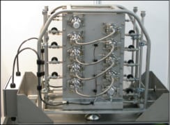
Dynamically mixed plug-flow reactors: Plug flow reactors need to be long and tubular to achieve good plug flow. While rotating stirrers can be designed for use in tubes, they generally present significant cost and fabrication problems. An alternative design for agitated tube reactors uses transverse mixing with free-moving agitator elements (Figure 6). These generate strong radial mixing in long tubes without the cost and technical problems associated with mechanical seals, baffles and shaft stability.
Advantages: Good mixing that is independent of fluid velocity through the reactor; Good plug flow; High flexibility in terms of reaction time range for a given tube length; Short, large diameter tubes that are easy to clean; Good handling characteristics for multi-phase mixtures. Very low pressure drop (gravity transfer can often be used)
Disadvantages: Subject to minimum diameter constraints, which limits the scope for strong exotherms where good temperature control is required
Typical applications: Processes with long reaction times, slurries and gas-liquid mixtures
Conclusion
The batch to continuous debate encompasses a broad spectrum of views. At one extreme are those who remain fully committed to batch methods. For some applications batch reactors are clearly a better solution or the only option. Processes with sticky materials for example are inherently unsuited to flow systems as are some slurries with large solids. In the absence of heat transfer or mixing constraints, batch reactors are also cheaper than flow reactors (although significantly less energy efficient). The resistance to change from batch to continuous is often justified on the grounds that existing batch processes are well optimized and offer little scope for improvement. This is true for some processes and particularly so when the cost of switching from batch to continuous is factored in.
Where there are mixing or heat transfer constraints however, the commercial benefits of flow reactors are often clear cut and compelling. It has been suggested that as much as 60% of commercially important non-polymer reactions could be run more efficiently in flow reactors [ 6] (and higher if peripheral benefits are included). To quantify these benefits, however, account needs to be taken of many factors that contribute to lower cost of goods. It also has to be recognized that most processes in use today were developed for batch reactors and would not necessarily be the first choice of method given the option of more-capable flow reactors.
At the other extreme of the batch to continuous debate are advocates of fully continuous processes where multiple steps are carried out within a single process train. The difficulty here is that good residence-time control is critical to many flow processes. Problems in one stage of a continuous process will impact the entire process train, and the system will only be as good as the least reliable step. As process equipment and knowhow develop in this field, the scope for integrating multiple steps will improve, but as things stand, multi-step continuous processes will remain the exception rather than the rule.
The near term future for chemical process technology must lie between the extremes of fully batch and fully continuous [ 7]. There are many common processes where incumbent methods are severely constrained by heat transfer and mixing limitations. Integrating flow reactors within existing batch processes for the right applications will contribute to: smaller equipment, greater plant flexibility, fewer batch failures, improved yield/quality, improved safety, lower energy costs and reduced solvent use. Progress in this area, however, will depend on a broader understanding of the subject in terms of methods for identifying suitable applications for flow reactors, a better knowledge of the available equipment and systematic methods for process development.
Edited by Dorothy Lozowski
References
1. Nichols, J., Innovations in Process Technology for Manufacture of APIs and BCPs, Pharm. Eng., Vol. 28, No 5, Sept./Oct. 2008.
2. Levenspiel, O., Bischoff, K., “Backmixing in the Design of Chemical Reactors” Vol. 51, Dec. 1959.
3. Eslinger, J., De Dietrich Process Systems, Bulletin BP 8, F-61170, Sept. 28, 2004.
4. Capretto L. and others, “Micromixing Within Microfluidic Devices, Topics in Current Chemistry”, Vol. 304, pp. 27–68, 2011.
5. Levenspiel, O., “Chemical Reaction Engineering”, 2nd Ed., John Wiley and Sons, 1972.
6. Calabrese, G.S. and Pissavini, S., From batch to continuous flow processing in chemicals manufacturing, AIChE J., Vol. 57, No. 4, pp. 828–834, 2011.
7. Roberge, D.M. and others, Microreactor Technology and Continuous processes in the fine chemical and pharmaceutical Industry: is the Revolution Underway?, OPRD, Vol. 12, pp. 905–910, 2008.
Author

Robert Ashe (AM Technology, The Heath Business & Technical Park, Runcorn,Cheshire, WA7 4QX, U.K.; Phone: +44 (0) 1928.515454; Email: robert.ashe@amtechuk.com) is a chemical engineer with over 35 years of experience in fine chemicals, pharmaceuticals and food manufacturing. Much of his career has been devoted to chemical plant design in high-value chemical manufacturing. In 2000, he co-founded AM Technology with David Morris. This company specializes in the manufacture of flow reactors and holds a broad portfolio of patents for dynamic mixing in tubes.