Gas turbines are widely used throughout the chemical process industries (CPI) because they allow for high power output and high overall efficiency at relatively reasonable costs. In recent years, a variety of factors and ongoing technology advances have contributed to the continuing evolution of the gas turbine systems. These include the following:
- Overall efficiency and performance improvements
- Capacity and power density increases
- The introduction of various new technologies
- Tighter environmental, health and safety (EHS) standards, expectations and regulations
- Higher reliability and availability
- More compact package design
- Greater expectation of easy access, and ease of operation and maintenance
The gas turbine business is a dynamic market with new designs introduced during each decade. As a result, over the past 40 years, the turbine temperature capability has advanced by approximately 10°C per year, corresponding to a roughly 1.5–2% increase in the power output (for the same gas turbine size), along with a roughly 0.4–0.6% improvement in the simple-cycle efficiency every year (on average).
The packaging of a gas turbine is the practice of combining and integrating machineries and components for specific application and plant settings. Packaging a gas turbine typically involves customization of the design to create the most appropriate site-specific solution. Packaging decisions typically revolve around the compressor trains, large pumps, special electrical power-generator and other units for CPI plants..
Currently, the aero-derivative gas turbine is preferred for CPI applications over other types of gas turbines (such as heavy-duty frame gas turbines), because it provides superior performance in terms of operational flexibility, efficiency, compact sizes, light weight and advanced packaging concepts. An aero-derivative gas turbine consists of two parts — an aircraft-derivative gas generator section, and a free-power turbine section. The gas generator is derived from an aircraft engine that has been modified to burn fuels that are typically available in CPI units (such as natural gas).
Valued traits of the aero-derivative gas turbine include its ability to be started up and shut down quickly, its ability to properly cope with load changes, and its high efficiency and variable-speed capability. All of these attributes make these designs superior options compared to traditional industrial, heavy-frame gas turbines.
High efficiency is one of the important issues that encourages the use of aero-derivative gas turbines. As a very rough indication, the efficiency of aero-derivative gas turbines is around 9–15% greater than the efficiency of comparably sized, heavy-frame gas turbines.
Over the lifetime of most gas turbines, the initial cost accounts for about 10% of the total lifecycle cost. The operating and maintenance costs account for roughly 18% of the total lifecycle cost. Fuel is typically the biggest cost factor — accounting for about 72% of the total lifecycle cost— and this underscores the critical role of turbine efficiency.
While significant strides have been made in the energy efficiency of gas turbines over the past 30 years, these improvements can mainly be attributed to better integration of the gas turbine within a modern CPI plant (particularly the heat recovery). Integration is the key for gas-turbine packaging. In simple terms, integration refers to the engineering practices and procedures for matching a gas turbine in the plant, particularly with surrounding and related facilities, for better overall combined operation.
Thanks to today’s modern designs, optimal power and heat integration account for the majority (roughly 68%) of the overall efficiency improvements of the gas turbine packages that have been realized over the past three decades. Improvements in the equipment (such as better lubrication systems) and the machinery designs (such as the use of better axial compressors or turbines), and improvements in related processes (for instance, combustion processes) are responsible for around 18% and 14%, respectively, of the overall efficiency improvement.
These aspects underscore the importance of proper power-and-heat integration in modern CPI plants. Integration must be taken into account during the design of the gas turbine packaging. For instance, a good packaging concept can facilitate maximum heat recovery from the exhaust gas of turbine section, which can significantly affect the heat integration and overall efficiency. Figures 1 and Figure 2 show examples of modern turbines used in CPI plants.
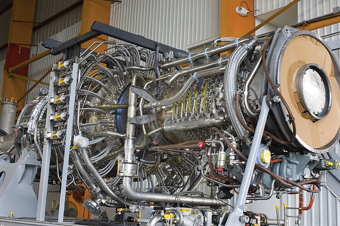
FIGURE 1. Shown here is an example of a modern, aero-derivative gas turbine for a CPI facility. This 35–MW gas turbine is used for mechanical drive applications and power generation. The 90-kg/s hot gas exhaust has a temperature of roughly 550°C, which offers a lot of opportunity for heat recovery and proper heat integration with the facility. Its modular design, coupled with its split compressor casing, in-place blade and vane replacement, in-place hot-section maintenance access, and external fuel nozzles, allow for easy and timely repair and refurbishment
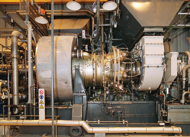
FIGURE 2. In an example of a modern gas turbine with good aerodynamics and advanced combustion technologies, this twin-shaft gas turbine achieves a useful power output of around 13–14 MW. Thus, this gas turbine model has been used for both power generation and mechanical drive. This is an example of a modern twin-shaft gas turbine that combines aero-derivative and heavy-duty technologies in one advanced gas turbine. The turbine permits an efficiency of about 35–36% for operation in a simple cycle. Adding a heat-recovery system will the improve overall efficiency. This machine has an excellent power-to-weight ratio in its application range. (Photo used with permission from Siemens)
Industrial turbine options
Industrial gas turbines range from microturbines to much larger designs. Often, microturbines are rated below 40 kW, and have an installed cost of nearly $1,000/kW and provide an efficiency around 15–20%. By comparison, large gas turbines (rated above 25 MW) typically cost around $300–400/kW and have an efficiency above 35%.
There are different turbine designs, including single-shaft designs (air compressor and power turbine on the same shaft), twin-shaft designs (for instance, air compressor and its turbine on one shaft and power turbine on another shaft) and multi-shaft designs. Theoretically, each shaft can have either two or three bearings. Some single-shaft designs have long shafts, and these may be better supported by three bearings.
In general, the two-bearing design is preferred in single-shaft gas turbines. Three-bearing solutions can cause some problems (such as alignment issues developed by the center bearing at the hot zone). They are the only available options for very large, single-shaft machines However, in CPI applications, these designs tend to be more rarely used (reserved for very specialized situations).
Generally speaking, the preferred gas-turbine casing is a horizontally split design that allows for easy access. Vertically split casings are used in high-pressure machinery designs; they usually offer some difficulties in access and maintenance. Figure 3 shows an example of a modern, large gas turbine with a horizontally split casing.
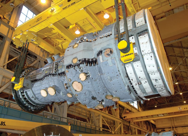
FIGURE 3. The modern, horizontally split gas turbine casing shown here is an example of a large and modern gas turbine. Today’s advanced turbines are sophisticated and complex systems that allow for overall efficiencies above 50% (Photo used with permission from Siemens)
The internal design of each gas turbine model can affect the packaging designs, and vice versa. Some problems arise when there is a major change in the number of blades between stages. Some specifications allow for a slight rubbing of rotating blades or labyrinths in shrouded rotating blades. However, this is not a popular option for CPI operators, where excessive rubbing is always considered to be unacceptable.
There is a general tendency in many gas-turbine applications for CPI units to increase the part-load operation capabilities (a wider partial-load range that has performance and operation quality that is comparable to the full-load service). For a gas turbine that is used in an integrated arrangement in a CPI plant (that is, one that uses any form of the heat recovery), there is a preference to keep more or less the same firing temperature over the entire partial-load operating range. The airflow and hot gas flow could be variable, but all of these parameters should be carefully evaluated, and proper limits should be set. Modern gas turbines are very sensitive to the back-pressure (from the hot exhaust-gas ducts, the heat-recovery unit, the stack and others).
Gas turbine packaging
Very large modern CPI plants and newer generations of small-scale CPI units both present unique challenges when it comes to the gas turbine packaging. In recent years, there has been a renewed interest in small-scale CPI plants in different parts of the world, particularly in some developing countries. The packaging of a gas turbine for such smaller-scale CPI facilities must be done in such a way as to minimize the total equipment item count (and process steps) and optimize the capital costs and footprint, while at the same time obtaining the highest possible efficiency and reliability.
On the other hand, some new, very large CPI plants offer other types of challenges. Over the past 40 years, in some CPI sectors, the throughput per production train has multiplied by a factor of about 5 to 10, while the overall efficiency of the gas turbine packages (used in those production trains) has nearly doubled. At the same time, the duration for construction and commissioning is reduced, thanks to improvements in modular works and prefabrication for very large and complex gas turbine packages. All these factors present some challenges for modern gas turbines.
Deep integration is a new term used for modern gas turbines in advanced plants; it means integration and matching a gas turbine in the plant (surrounding and related facilities) in a much better way compared to older designs. For instance, such integration involves much better use of heat recovered from the gas turbine exhaust. The deep integration of power, heat and other operational aspects, coupled with the use of modular design concepts, have been the keys for success in modern gas turbine packaging. Figure 4 shows an example of a very large gas turbine installation. The air-inlet filter and the exhaust-gas stack are also shown.
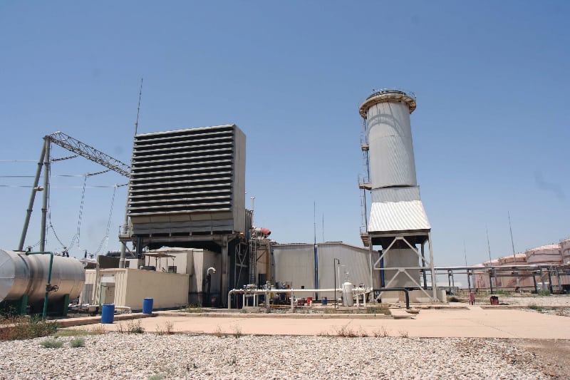
FIGURE 4. A example of a very large gas turbine installation. The air inlet filter and the exhaust gas stack are also shown.
Gas-turbine fuel system
If it is available in a CPI plant, natural gas is the best fuel option for most gas turbines. The use of natural gas can reduce maintenance costs, reliability issues and emissions compared to liquid fuels.
However, despite the advantage of natural gas, about 30–40% of all gas turbines operate on liquid fuels, which can vary from light liquid fuels (naphtha, kerosene, and others) to heavy fuels. The fuel selection depends strongly on the CPI application. Heavy fuels often bring reliability problems, higher emissions and fast degradation. In some cases, a 10–15% reduction in the produced power has been reported for some gas turbines using heavy fuels within a few weeks after startup. However, users should note that aero-derivative gas turbines cannot use heavy fuels.
The fuel — whether gas or liquid — should be injected at a pressure of about 3–5 bars above the air-compressor discharge pressure. The fuel compression and pumping systems — particularly the fuel-gas compressor systems are important and require close attention when designing the overall gas turbine packaging. It is important to select the right, oil-free compressor for such applications, with correct compression characteristics and proper pressure capabilities.
The fuel-treatment system also plays a critical role for many gas turbines, since unwanted components in the fuel stream can cause performance or reliability issues (such as the formation of deposits or corrosion) or high emissions.
Modern gas turbines that use low-NOx technologies tend to be particularly sensitive to liquid or dirt carryover within the fuel gas. Thus, they generally require a clean and heated fuel gas. Superheating is the only certain method for ensuring the elimination of any liquid carryover in fuel gases. Generally, a well-designed fuel system — one that has all of the required separators, multiple filtration stages, a knockout drum, heater(s), accessories, auxiliaries, instruments and monitoring devices — is a good investment that will provide payback over time by helping to ensure trouble-free operation of the turbine.
Filtration at the air inlet
A proper filtration system for the inlet air is also important; otherwise unwanted particulate matter in the inlet air can cause erosion and blade contamination or fouling. The minimum requirement should be a high-efficiency, multistage, air-filtration system to remove particles down to 1µm (or less) from the inlet air.
Old-fashioned filters only remove particles above 3µm in dia. However, in any cases, small particles (below 3µm in dia., and even as small a 1µm) are to blame for gas turbine fouling and other issues, and such particles are often able to evade capture by old-fashioned filters. Some advanced filters are now available to remove particles down to 0.3µm from the inlet air.
Starting device
The sizing of the starting device for the gas turbine is an important consideration for any gas turbine. In a free-power turbine design (including many aero-derivatives and some heavy-industrial type machines, such as twin-shaft and multi-shaft designs), the starting device does not need to rotate all turbine shafts and driven equipment. Rather, it only needs to be designed to overcome the torque needed to start the gas generator section.
In a single-shaft, gas turbine design (including many heavy industrial machines), the total train torque should be considered when sizing the starting device, as the starting device should rotate the single-shaft and coupled driven machines and equipment. A speed-torque curve of the gas turbine (and machineries coupled to it during the startup) should be respected during this sizing and proper safety margins should be considered. The starting device is often to blame for reliability issues, inefficient sizing, low availability, and so on, so be sure to give this critical component the proper attention during the specification of any gas-turbine package.
Gas turbine auxiliaries
Standards for gas turbines and gas turbine auxiliaries (such as API-616, API-614, ASME and others) have tried to note the minimum requirements for the specified applications in the code. The major problem is that some useful requirements are listed as optional in the gas-turbine-related codes. As a rule-of-thumb, users should follow all requirements (both mandatory and optional requirements) for the gas turbine packaging. Sometimes, requirements should be specified beyond the codes, to achieve a high level of performance and reliability. Consider the following:
- Codes are usually updated only every 5–10 years and recent technologies, innovative designs, latest observations or new experiences typically need several years to come to the attention of (and be accepted by) code task-force team(s) and then be incorporated into the codes
- The teamwork that is involved should have representatives from different groups, vendors and others, with various backgrounds and goals, to prepare for compliance of relevant codes. Note: the main focus of the codes should not necessarily be the best performance and reliability (for the operators); rather, the final (or agreed-upon) specification should be an optimized set of requirements (or sometimes compromised ones). In other words, any user should know that some items specified in codes are not necessarily the best possible technology for operators and often it is necessary to specify some requirements in addition to- the codes
There is always a great concern about the lubrication oil system (generally called “the oil system”). A design that involves having the primary oil pump driven by the main machinery shaft is usually not acceptable for any high-speed turbomachinery (including the gas turbine). The high speed itself is one reason; it is not usually matched with lower speeds of oil pumps. The use of a gear unit to connect the oil pump to the turbomachinery shaft is often a poor solution, because an oil pump failure can mandate shutdown of the turbomachinery unit.
Horizontal oil pumps are always preferred. The oil pump selection and packaging should be in a way to minimize maintenance and operation efforts. For instance, oil-suction pipes should be arranged to provide positive suction head on the oil pumps, with a slope toward the pump. Cast-iron casing is usually not desirable for any equipment (or machinery) in the machinery package or auxiliary systems, because it is a brittle material and can fail very quickly in emergency situations, particularly in the event of fire.
Generally, an auxiliary skid arrangement should be optimized to balance performance objectives and reliability goals, while maintaining easy access and maintenance requirements, and compact design. Heat exchangers are needed to cool the lubrication oil, which is often heated during operation. TEMA C shell-and-tube heat exchangers (with removable bundles) are well-known for auxiliaries, including lubrication oil skids. The oil pressure should be greater than the cooling-water pressure, to avoid the potential for water leakage into the oil in the case of an unexpected problem (such as exchanger tube crack or leakage). Water is on the tube side and oil on the shell side.
Plate-type heat exchangers are not popular in turbomachinery assemblies since they might clog or experience some other operational problems. An exception is for revamp projects with limited available footprints; but tubular heat exchangers may be used for small packages.
Gas turbine heat recovery
For some gas-turbine packages, heat recovery is the source of many problems and issues. One reason may be that in spite of the gas turbine, which is offered in standard models, the heat-recovery unit is usually a custom-designed system. The performance and reliability of the gas turbine package depend on the heat-recovery system. The design, fabrication and operation of such a heat-recovery system as an integrated part of the overall gas turbine package system. In the most common form, the exhaust gases from the gas turbine enter the heat recovery steam-generating (HRSG) system, where the energy from the hot exhaust is used to heat the water to produce steam.
Many HRSGs are designed in different modules and sections. In many cases, each HRSG has a pre-heater, an economizer and a superheater. The steam for modern steam turbines is usually superheated. Both vertical and horizontal HRSGs are commonly employed.
By contrast, once-through steam generators (OTSGs) are used in some applications because they are cheaper, simpler and more compact compared to other HRSG designs. OTSG systems do not have defined economizer, evaporator or super-heater sections. In simple terms, in an OTSG system, water enters at one end and steam leaves at the other end. There is no need for drums, various sections and many other auxiliaries (or accessories).
Typically, the hot gas exhaust from a gas turbine has ample oxygen. Therefore, the gas exhaust can be used in another combustion process to increase its temperature for a better heat recovery arrangement. The supplementary firing at the waste-heat recovery unit could be a feasible option to achieve the maximum possible efficiency. This design is also becoming popular in modern CPI plants, which require a better operationall flexibility since, theoretically, supplementary firing can offer some operational flexibility.
However, this complex design (supplementary firing and HRSG) requires special care. For example, the transfer duct (between the gas turbine exhaust and the waste-heat recovery unit) should have a sufficient length to ensure complete combustion and avoid direct flame contact on the heat-transfer surfaces. On the other hand, the duct system length should be optimized, in order to limit the heat loss, manufacturing costs and overall system footprint.
Control and monitoring
The temperature of the turbine blade metal must be monitored to ensure reliability of the first row of turbine blades and other hot sections. The use of pyrometers to sense the blade metal’s temperature is offered for some gas-turbine packages for CPI units. Very high pressures in air-axial compressors of gas turbines have caused these compressors to have a very narrow operating range between the surge and the choke. The axial compressors of gas turbines tend to be very sensitive to dirt and fouling, and even slight modifications to the blade (vane) angle.
Dynamic pressure transducers that detect the surge and other flow instabilities in the air axial-compressor are an important element for some gas turbine packages. The stability in the combustion process could also be monitored by the same method. The application of dynamic pressure transducers in the combustion sections, especially in modern, low-NOx combustors, could ensure that each combustor section is burning evenly without any issue, problem or instability.
Lubrication oil for gas turbine
The lubrication oils for gas turbine are subject to a wide range of harsh conditions, such as extreme heat, high contamination, inadvertent mixing with different substances and more. These effects can degrade the integrity of the oil base stock and deplete any additives, causing irreversible molecular changes and hence changes in the lubrication oils.
Most gas turbine trains use a relatively low-viscosity oil (compared to that used by gear units and reciprocating machines), for example, ISO viscosity grade (VG) 46.
A lubrication oil with optimum viscosity reduces the power waste for operation because frictional power involved in bearings and other lubricated parts would be reduced. The usual expectation by users is relatively low makeup oil for the gas turbine lubrication oil (say on average below 5–10% oil added per year). This low makeup requirement is a factor that encourages high-quality, long-life lubricant applications for a gas turbine. Usually, the oil in a gas turbine train (without a gear unit), if selected properly and maintained correctly, does not need to be drained and replaced with much frequency and thus could last for a relatively long time. It is hard to note an expected life, but it could be a matter of years. The gas turbine oils should be well-maintained (such as avoiding possible contamination by water and other fluids, using good seals, and so on) to extend their service life and simultaneously provide the maximum machinery performance.
Generally, for gas turbines operating at high temperatures, oxidation of lubrication oil could be an important issue. High temperature directly affects the oxidation. Heat also reduces the oil life. For high-temperature applications, the oxidation rate is usually doubled for every 10°C increase in the oil temperature.
Lubrication oils can also fail because of contamination. A good solution is to use the correct sealing system to eliminate the potential for gas leakage to the oil.
Any additives used in a gas-turbine lubrication oil should extensively be verified and tested. The oil and additives must be carefully formulated in a tightly controlled process. The key to an excellent lubrication oil is to retain the desired properties. Successful (long-term satisfactory operation) references are important. In other words, it is important to check if proposed lubrication oil were used in similar gas turbines in more or less the same conditions successfully.
The lubrication oil in most modern aero-derivative gas turbines and advanced high-efficiency gas turbines could be in contact with metal surfaces above 200°C. These high temperatures, and the possibility of cyclical operation, can result in significant thermal and oxidative effects on the oil. For these applications, sophisticated synthetic oils are the only available options. Mineral oils used in old-fashioned gas turbines are not usually suitable for modern gas turbines.
Instead of degradation occurring in an orderly, predictable fashion, many lubricants that are used in modern gas turbines fail rapidly. And some of the standard oil-analysis tests offer little indications as the gas turbine lubricant starts to degrade. Thus, it is critical to study previous lubrication oil behaviors in similar gas turbines and operating situations.
“Ferrography” is a technique that provides valuable information about wear evolution in machinery through analysis of a representative lubrication oil sample. In an analytical ferrography study, the solid debris suspended in a lubricant sample is separated. The solids are then passed across a bipolar magnetic field. After that, a solvent “wash” cycle removes any lubricant remaining on the substrate, resulting in a “ferrogram” where the particles are all arranged by size and permanently attached to the slide for optical analysis using a bichromatic microscope. The particles are then examined and classified by size, shape, concentration and metallurgy. The information carried by the wear particles is valuable for the identification of the wear mode and mechanism.
Analytical ferrography can be particularly effective in the detection of soft contaminants and in the identification of their nature. This can be a powerful technique to identify the oil-related issues of the machinery, root-cause analysis, the morphology and characteristics of the insoluble particles, and the progressive mechanism of varnish formation. While the ferrography test procedure is lengthy and requires highly skilled analysts, the benefits can outweigh the costs. This is a recommended test if any abnormal wear is observed.
Fourier transform infrared (FTIR) analysis can be useful to measure organic molecular components, monitor additive depletion and identify organic degradation byproducts (oxidation). FTIR is the preferred method of IR spectroscopy. In IR spectroscopy, IR radiation is passed through a sample. Some of the IR radiation is absorbed by the sample and some of it is passed through (transmitted). The resulting spectrum represents the molecular absorption and transmission, creating a molecular fingerprint of the sample. Like a fingerprint, no two unique molecular structures produce the same infrared spectrum.
Edited by Suzanne Shelley
Author
 Amin Almasi is a rotating-equipment consultant in Australia (Email: amin.almasi@ymail.com). He previously worked at Worley Parsons Services Pty Ltd. (Brisbane, Australia), Technicas Reunidas (Madrid, Spain) and Fluor Corp. (various offices). He holds a chartered professional engineer license from Engineers Australia (MIEAust CPEng – Mechanical), a chartered engineer certificate from IMechE (CEng MIMechE), RPEQ (registered professional engineer in Queensland) and he also holds M.S. and B.S. degrees in mechanical engineering. He specializes in rotating machines, including centrifugal, screw and reciprocating compressors, gas and steam turbines, pumps, condition monitoring and reliability. Almasi is an active member of Engineers Australia, IMechE, ASME, Vibration Institute, SPE, IEEE, and IDGTE. He has authored more than 60 papers and articles dealing with rotating machines.