Management of process plants requires the understanding and application of the fundamental tenets of safe design, construction, and operation of each facility. In that context, many years of practical experience with systems that use very high-temperature organic heat-transfer media has led to much knowledge regarding design features to adopt and those that should not be repeated.
For the media itself, the severe stresses of extreme operating temperatures involved can sometimes narrow the number of candidate fluids to one: the eutectic mixture of diphenyl and diphenyl oxide (DP:DPO; Figure 1). This article shares best practices that have been developed over the years to ensure the safest possible use of this heat transfer fluid (HTF). Effective methods to identify and determine the order of magnitude of leaks are discussed. Meanwhile, a review of the concepts necessary for effectively maintaining a leak-tight system is presented. And, for occasions in which unexpected leaks do occur, a thorough explanation of the fire risk is offered and approaches that can minimize ignition potential and property damage are addressed.

Introduction
Basics of system requirements
Process plants require heating and usually cooling capabilities. A “typical” HTF system is composed of an energy source, such as fired heaters or waste heat recovery systems; pumps to force the fluid flow; an expansion tank to absorb the volume expansion of the fluid; and last but not least, a heat consumer. High-temperature heat-transfer systems are usually closed systems, and hence, a release of fluid can typically only occur in case of accidents or malfunctions. Heat transfer media used in such systems are usually water-and-steam, water based fluids, mineral oils or synthetic heat-transfer fluids specially designed for this purpose. Based on their physical and chemical properties, such fluids imply certain handling risks in addition to the general risk of operating an HTF system.
Besides classical process plants in the chemical, petrochemical and plastic industries, two other applications have recently come into the focus by utilizing large volumes of DP:DPO HTFs (see box entitled Large volume applications): electrical energy production by concentrating solar power (CSP) and converting natural gas into synthetic oils in a process called gas to liquids (GTL).
As with all HTF systems, the design must accommodate the volume expansion of the heating fluid, which is typically provided by an expansion or surge tank of sufficient volume and headspace. For plants using DP:DPO near its maximum temperature of 400°C (750°F), the volume expansion from ambient temperature is greater than 30% [ 1]. The expansion vessel is typically pressurized to keep the HTF in liquid phase and is equipped with a vent system to permit the exit of nitrogen, degradation products, and a portion of DP:DPO into the ullage vent-collection system. The extensive network of HTF handling piping, instruments, and vessels, combined with elevated vapor pressures, can increase the potential for leaks from systems if adequate design and maintenance measures are not also incorporated.
Incident history of leaks, fires
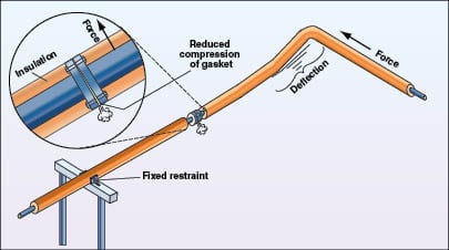
Examination of the leak history from DP:DPO handling systems indicates that the primary sources are flanged connections, flexible connectors or rotary joints, and pump seals. Fire-resistant gaskets used in DP:DPO service can require substantial compressive force on the gasket face. In cases where insufficient flexibility is provided in piping networks (Figure 2), the resulting force applied to the flange pair reduces compression on a portion of the gasket, leading to leakage. Such leaks can sometimes be addressed by tightening sufficiently, but only as a temporary repair. Permanent repair will require gasket replacement and improved piping flexibility.
Stainless-steel flexible hoses were first installed on the early solar energy generating systems (SEGS) in the California Mojave Desert in the 1980s. Some of the original flex hose remain in service today, while most has been replaced over time. Experience in the mode of failure finds that the hose develops small cracks through which the DP:DPO fluid seeps slowly at first. The leakage can be visually observed as a darkened area on the outside of the hose assembly. Prompt maintenance can permit the piping section to be shut down and isolated for hose replacement prior to a rupture. When proper experience and care is applied during hose installation, the hose can be kept free of the torsion and misalignment that reduce its service life. It is important to follow hose manufacturer recommendations on inspection and replacement frequency, as the hose has smaller wall thickness than rigid pipe.
Rotary joints have the advantage of using greater wall thickness for a more robust joint, yet have the flexibility to support the daily cycling demands of the mirrored rows of heat collection elements (HCEs). Designs can incorporate high-temperature, metal-to-metal seals and can include provision for injectable, graphite-based packing for maintaining adequate sealing. Some users, however, have reported that some of the rotary joints failed more, and without warning.
Whether from flexible hose or rotary joints, the close proximity of these devices to nearby ignition sources can lead to the ignition, or even autoignition of a released cloud of HTF mist if surface temperatures exceed 1,100°F (593°C). For safety of personnel, response typically involves remote isolation of the piping circuit to allow the fire to burn itself out in remote or non-congested areas. Alternate measures may be appropriate to protect against peripheral damage in more congested areas. Extinguishing the fire prior to stopping the HTF release may result in later, repeated ignition. Operating practices must incorporate the frequent monitoring of the integrity of field piping systems through regular inspections and/or remote video surveillance, or both.
Pumps in DP:DPO service can have single or double mechanical seals. Some of the pumped liquid may be required to adequately lubricate sealing surfaces during operation. Excessive temperatures at the seal faces can also vaporize the HTF resulting in no lubrication and ultimately cause mechanical damage to seal face materials. This mechanism can create particulate matter that erodes the seal face and create a separation of seal faces, thereby resulting in leakage. A seal flush can be effective in minimizing excessive seal wear by removing harmful corrosive or fouling deposits with filtered fluid [ 3].
It should be noted that while infrequent insulation fires are experienced in very-high-temperature organic HTF systems, it is extremely rare in DP:DPO systems. DP:DPO has a lower relative-normal boiling point than other high temperature HTFs, permitting its more rapid evaporation from soaked insulation before it can be heated to its autoignition temperature (AIT) by the oxidation exotherm within porous insulation. Cellular glass insulation has proven most effective in interrupting the mechanism of HTF insulation fires among most organic HTF chemistries.
Consequences of leaks, fires
There are no positive consequences of leaks and fires, except perhaps the heightened awareness of design or construction flaws, which leads to improvement. The immediate negative consequences include risks to human life and health from released fluid ignition and fire fighting response, or inhalation of partially combusted hydrocarbons. Personnel should be trained and equipped to respond by remotely isolating systems, and staying out of the path of smoke, vapors and liquid runoff. In CSP plants, the amount of fluid contained in a 100-m mirrored row with 70-mm O.D. heat-collection elements will be limited to nearly 0.33 m3 (87 gal), plus the volume contained in piping up to the isolation valve(s). Much of the HTF released from piping containment will flash into the vapor phase, and then quickly condense into a mist cloud. The balance will rapidly cool in contact with equipment and earth, remaining in liquid phase. Contaminated soils will require disposal or treatment per regulatory requirements, possibly including incineration or bioremediation. Hot fluid released and collected should not be reused, as it will have become oxidized and perhaps contaminated. Equipment wetted with HTF condensate should be cleaned for proper housekeeping, and to remove residue that could potentially fuel a future fire.
In areas where leakage is of highest risk (such as flex hose or rotary joints, pump seals, valves or instrument manifolds, and so on) efforts should be made to limit the amount of instrumentation and wiring potentially exposed to fire. Doing so will minimize the downtime required to return the equipment into operation. Any equipment, piping, instrumentation, insulation or controls that have been exposed to fire or DP:DPO spray should be inspected by qualified engineers and technicians for reliable operating integrity, prior to returning it into service.
Fluid Chemistry and Inherent Properties
Formulation
DP:DPO heat transfer fluids are a eutectic mixture of diphenyl and diphenyl oxide. These two components exhibit the highest thermal stability available among organic heat-transfer media. Their eutectic ratio ensures the lowest freeze point possible, thereby creating the widest working range of temperature. As diphenyl and diphenyl oxide exhibit tremendous thermal stability, the weakness of the specific fluid formulation would then lie in its impurities. Therefore, it is most desirable to have very high assay of the two primary constituents, and limit the percentage of impurities possible. Doing so protects thermal stability of the fluid and also ensures that the physical properties of the HTF will have minimal deviation from its key components.
Low chlorides content (< 10 ppm) ensures long life of stainless-steel system components without excessive risk of stress-corrosion cracking. There are SEGS systems, for example, that have been utilizing low-chloride-content heat-transfer fluid since the 1980s with no reported cracking issues. Low chlorides content should therefore be a requirement of DP:DPO fluids used in plants to help maintain longterm mechanical integrity.
Tendency toward leakage
Operators of high temperature, organic heat-transfer fluids should be aware of the potential for leakage of DP:DPO from components that may be leak-tight when pressure tested with water. It has been noted that, “the physical and solvent properties of organic fluids allow the fluids to penetrate ordinary valve and pump packing and bleed through porous materials including some cast irons” [ 4]. For piping flanges, fire-resistant gaskets are preferred, which can require higher compression to adequately seal as compared to softer gasket materials. To help minimize leak potential and keep the DP:DPO confined within the system, engineers and safety professionals have developed key practices as outlined later in the section on preventing leakage.
When DP:DPO eutectics freeze, the material contracts in volume by over 6%. If the product then melts between frozen plugs of product or other mechanical boundaries, tremendous pressure can result, possibly leading to release of the product through the weakest constraint, such as flanged connections, valve stems, pump seals, and so on. When thawing a frozen section of piping or equipment, it is very important to accommodate the expansion in volume into unobstructed piping or equipment.
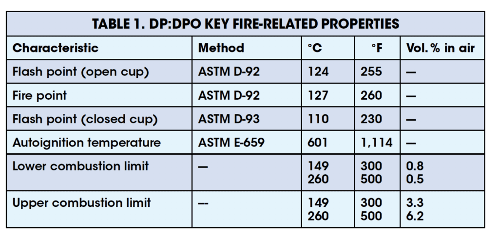
Key fire-related properties
Key properties of interest in gauging the potential for fire with organic heat transfer fluid are provided for DP:DPO in Table 1.
Minimum ignition energy (MIE) is a measure of an amount of energy below which an explosive mixture in air will not be affected, and above which the mixture can be affected. Measured values for heat transfer media are not readily found in published literature. As T. H. Pratt explains, the MIE concept applies only to capacitive spark discharge and that, based upon numerous factors, “one must recognize that MIEs vary with most everything” [ 5]. Taking this into account, NFPA 77-2007 states that the MIE for most saturated hydrocarbon vapors is near 0.25 mJ, and that mists can have MIE values one or two orders of magnitude higher [ 6]. This value can have considerable deviation from the MIE experienced in actual field environments.
Preventing leakage, component selection
Reliable system design
Complete guidance on system reliability cannot be adequately covered within the constraints of this article; however, many important concepts are provided herein in support of designers and operators. Economics of projects often require use of the lowest cost materials that are fully compatible for the service to be utilized. Since the mid-1970s and the development of the first low-chloride (< 10 ppm) formulation of heat transfer fluids, stainless-steel metallurgy for instrument tubing and specialized equipment could be used without fear of chlorides-related stress cracking potential. It is important to note that any significant extension of operating temperatures above those currently used in DP:DPO HTF systems would require more exotic and costly alloys for piping and equipment, as well as the development of satisfactory, new heat-transfer fluids. Useful reference standards and codes are included in the References section [ 7 – 14].
With the HTF being significantly above its normal boiling point during operation, adequate overpressure protection in the form of pressure relief valves (PRVs) and rupture disks must be provided with adequate capacity for relief between selected points of isolation. With proper design considerations, the PRVs can be installed in series with rupture disks to minimize fugitive emissions from the system. General good practices for HTF system design are typically available from the HTF manufacturer, including information on system components, filtration and expansion tank design.
Piping, flanges and gaskets
Seamless carbon steel has been demonstrated as an appropriate piping material for use with organic HTFs in plants up to their maximum bulk operating temperatures. Threaded fittings in piping are to be avoided in preference to all-welded construction. Graphite-based, paste thread sealants have demonstrated marginal success with threaded connections that cannot be avoided, such as instrument connections, pump-casing drain plugs, and so on.
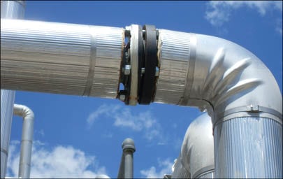
With any metallurgy employed, the linear expansion and contraction of the piping must be accommodated by use of expansion loops or flexible connection members, and pipe supports should be generously spaced to prevent sagging. When thin-walled expansion joints are selected, manufacturers’ recommendations for inspection and replacement frequency should be strictly followed. Piping should be provided with “shoes”, which can slide unrestrained axially on the pipe supports with thermal cycles. Where flanges are necessary, Class 300 and Class 600 ring-joint flanges or raised-face flanges are commonly used. While the number of flanged pairs should be minimized to reduce the number of potential leak points and fugitive emissions, designers should consider maintainability and install such connections to all major pieces of equipment and in other key locations for ease of servicing equipment (Figure 3).
When used with raised-face flanges, gaskets should have a metal ring for blow-out resistance and graphite-filler within 316 stainless-steel, spiral windings for fire resistance. A number of manufacturers offer such gaskets, and some designs provide more-exotic-alloy spiral windings for improved memory and longer use-life for cycling temperature services. A key necessity for flanged connections is to ensure that adequate and uniform sealing compression (seating stress) is provided on the gasket faces. Data on compression force of gasket surfaces are available from gasket manufacturers, which will then determine proper bolt/stud/nut selection and torque requirements.
For non-circular gaskets, such as in some pump casings and valve bonnets, foil-inserted graphite has been successfully used. Where larger gaskets are required for heat exchanger heads with partitions, and so on, foil-inserted graphite, tang or corrugated metal-inserted graphite can be used. With any gasket type selected, proper installation techniques prescribed by the manufacturer should be followed.
Pumps and pump seals
Pumps in HTF service are generally of cast steel for withstanding the stresses of thermal shock. Pumps in high temperature service can have double mechanical seals, or can be of a sealless design. The pumped fluid is used to lubricate and cool bearings in either type. Excessive temperatures at mechanical seal faces (typically tungsten carbide, stellite, or silicon carbide) can vaporize the HTF resulting in no lubrication and mechanical damage to seal face materials. This mechanism can create particles that can erode the seal face and create a separation of seal faces resulting in leakage. Therefore, stuffing box and seal gland cooling is important to maintain lower temperatures and also improved lubricity of the HTF. A seal flush can be effective in minimizing excessive seal face wear and particle accumulation on flex metal bellows by removing harmful deposits with filtered fluid [ 15].
Valves
Valves in DP:DPO service may include forged- or cast-steel, or stainless-steel bodies, balls, plugs and disks. 13-Chrome (Cr) stems and 13-Cr or stellited seats should be considered. Fire-resistant graphite packing should be specified in select configurations available. Bellows seal designs can provide physical barriers for reduced emissions and leaks. With frequent updates of valve feature availability, the designer should always consult with the valve manufacturer to consider the latest innovations available. Soft-seat materials should be avoided since they can burn out in case of fire, potentially adding to the complexity of the HTF release. Small valves with welded end-connections should be considered to reduce potential leak points, and larger valves should be considered with flanged end-connections. Connecting piping should have adequate flexibility to minimize torque induced from thermal expansion and contraction of piping applied to flanges, which may develop leaks.
Maintenance practices
Simply put, three keys for adequate maintenance practice are as follows:
1. Respond to identified leaks promptly with repairs
2. Repairs should address the cause of the failure, and not just the consequences of the failure
3. Learn, document, and practice the recommended preventive maintenance of the equipment
Leak Detection
Human senses
DP:DPO fluid can be operated in liquid or vapor phases. When there is leakage, even above its normal boiling point, the vapor emitted can quickly condense to form a visible, near-white mist cloud. The cloud quickly increases its transparency as it dissipates. For small leaks it may be possible to observe liquid droplets present at the source of the leak, such as valve stems, pump seals, flanges, and so on, as well as on the ground. As mentioned earlier, a small leak from a flex hose can appear as a darkened, wetted area. When cool ambient conditions permit, frozen DP:DPO may be observed as white crystalline solid. Visual detection capability for leaks can be greatly enhanced by use of remote video-surveillance monitoring.
The DP:DPO eutectic mixture has been measured to have an odor threshold of 9 parts per billion (ppb) in air, making detection by odor possible without exceeding established airborne exposure limits for either component. In indoor areas, the airborne HTF may not dissipate readily, preventing easy tracing back to the leak point. In outdoor environments, the odor is more closely localized around the leak point due to the more rapid dissipation of the components in air. While odor may be a sensitive detection technique, the use of instrumentation is a preferred detection-and-measurement method with superior quantifying capability for leak tracing.
Specialized instrumentation
Instruments using the principal of photoionization are well suited for use in CSP and process plants. Typically, these instruments can readily detect DP:DPO concentrations in air as low as the ppb range. For realtime personnel exposure monitoring, the ppb sensitivity is appropriate to quantify exposure at levels below established occupational exposure limits for the fluid’s components. For maintenance needs, parts-per-million (ppm) sensitivity is sufficient to determine orders of magnitude of identified leak sources so that repairs can be scheduled on a prioritized basis. The instruments can be purchased as handheld units for lightweight mobility, or as fixed-mount, continuous area monitoring stations. The devices pull air samples through the instrument for measurements. Drawbacks include inability to distinguish DP:DPO vapor from other measureable organics and combustibles (although, this is not a problem in most CSP plant areas), and tendency to condense vapors within the sample inlet when sampling high concentration leak points. The internal condensation can require the instrument to be offline until disassembled for thorough cleaning. Experience in handling the unit can quickly overcome this issue. Cost of these instruments currently varies from approximately $3,000 for small, ppm handheld models, to $5,000 and higher for the ppb and fixed-mounted systems. They can be purchased with intrinsically safe certifications for use in hazardous areas.
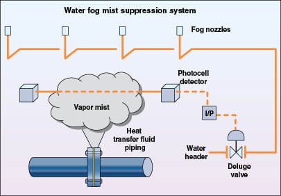
To prevent the potential ignition of vapor- and mist-cloud leaks within indoor areas with reduced ventilation, custom-developed instrumentation has been installed to automatically detect the presence of clouds of DP:DPO with the capability of automatically triggering water-fog deluge systems and alarms, initiating forced ventilation, and de-energizing area equipment with a continuous monitoring capability. This design has incorporated the use of multiple-sensor actuation to avoid accidental activation from only one monitor (Figure 4). The use of water-fog systems has been found in testing to rapidly reduce airborne DP:DPO concentrations to below combustible concentrations in air [ 16].
It is important to follow the manufacturer recommendations with respect to the use and maintenance of these instruments.
Process level indications
Today’s facilities will typically have installed instrumentation for the routine measurement of liquid level in process vessels, including bulk storage tanks, surge or expansion tanks and ullage vessels, condensate tanks, and others. Modern instrumentation often permits excellent level-trend capability so that response time to unexpected level changes is greatly enhanced by use of configured deviation alarms with a distributed control system (DCS). Common suitable instrumentation types can include displacer, differential pressure and radar within their respective design limitations of temperature. Externally mounted floats within stainless-steel chambers can provide 0 to 100% level indication and remote, continuous monitoring on DCS screens. Changes in liquid level in vessels can be a somewhat crude, but important component of detection material loss.
Potential fire scenarios
The prerequisite to a fire is a leak from point sources, such as described in the earlier section on incident history.
Insulation fires. Insulation fires are not uncommon with high-temperature, organic heat-transfer fluids. However, in one extensive study of such fires by Britton, he concludes, “Least prone should be DP:DPO types, which have very high AITs (above 500°C) and relatively low flash-points of around 130°C” [ 17]. DP:DPO-soaked insulation apparently avoids the insulation fire mechanism by its more rapid rate of evaporation out of the insulation than other higher-boiling heat-transfer-fluid chemistries, while avoiding the close approach of its autoignition temperature.
Spark- or flame-produced ignition. With DP:DPO fluid, a more expected cause of fire would be from spark- or flame-produced ignition. Releases of liquid DP:DPO above its fire point of 127°C (260°F) are susceptible to ignition from area sources, such as exposed electrical contacts, spark-producing tools, open flames and so on. However, hot HTF can rapidly cool once released into its environment, both by evaporative cooling and by conducting thermal energy into the heat sinks provided by the ground, equipment and so on. A good design practice is to provide sloping of underlying surfaces such that any liquid release can drain away from process equipment, thereby minimizing potential ignition. Also, once any release of HTF is observed, all spark-producing work should be halted until the situation has stabilized.
Autoignition. Autoignition of a DP:DPO cloud has been reported in one CSP plant where the HTF leaked in close proximity to the heat collection element (HCE). When a vapor or mist cloud of DP:DPO within its combustible limits of concentration in air contacts a surface at temperatures above the autoignition point of the HTF, it can ignite. The cloud is consumed rapidly and can continue to burn at the source of ongoing leakage until its flow is stopped. Where possible, designers are encouraged to consider incorporating remote isolation capability for piping circuits, so that the fuel to the fire can be safely interrupted.
Fire prevention & fighting techniques
Breaking the fire triangle
Three necessary components make up the fire triangle (Figure 5) for an HTF system: oxygen, an ignition source and fuel (DP:DPO). How do we address each of these successfully to avoid their fiery combination?
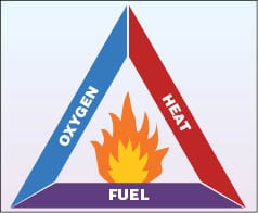
Oxygen. Within process vessels, provide blanketing with dry, inert gas. Nitrogen is typically used, and should be a minimum of 99% purity.
Ignition sources. HCEs of CSP plants are the previously identified point of AIT concern, as the surfaces can reach temperatures above the DP:DPO AIT, particularly when leakage reduces the flowrate of the HTF through the HCE. To date there has been no known provision made to avert the potential drifting of a DP:DPO cloud across the HCE. Upon the first detection of leakage from piping components in the proximity of potential ignition sources, prompt maintenance should be scheduled for repair or replacement. Potential for open flames (such as smoking, welding and cutting torches) can be addressed by strict compliance with adequate administrative controls. Electrical area classification design should be properly addressed so that it conforms to applicable code requirements. This should establish a minimum radius around each potential DP:DPO leak point, and should be determined according to specified standards for the requirements of electrical enclosures, switches, motors and so on.
Fuel (DP:DPO). Use of HTFs at very high temperatures often requires an organic heat-transfer fluid of highest thermal stability, which is the DP:DPO eutectic fluid. The proper approach to eliminating the presence of DP:DPO outside of its containment is by careful design and installation of the system and its components, and incorporating a culture of effective preventive maintenance and inspections for the system’s proper operational integrity. For the unexpected leaks, designs incorporating remote isolation capability can help minimize DP:DPO release and personnel exposure during these events.
Fire fighting response
For small or incipient-stage fires with a limited and minimal source of fuel (DP:DPO), the use of a handheld fire extinguisher can be an effective and appropriate selection to extinguish a fire. Approach to the fire should be from upwind to avoid breathing partially combusted materials, with standard sweeping discharge of dry-chemical or carbon-dioxide media. Consider placement of 20–30 lb (9–14 kg) dry-chemical fire extinguishers in easily accessible locations at each level of structure where the fire potential exists in HTF handling areas [ 12]. Personnel must be properly trained in the operation of selected extinguishers and techniques for approaching and extinguishing HTF fires.
Larger dry-chemical units are available on trailers and can be quickly transported to distant locations within the expanse of a facility. It is recommended that personnel intended to operate such equipment receive specialized training and certification prior to being authorized to respond. Onsite fire brigades can address fires much more rapidly than offsite fire departments, and can help to minimize potential damage, system downtime and repairs.
As mentioned earlier, fires involving larger releases of HTF in non-congested areas of a facility that are beyond the capability of incipient-stage response techniques are perhaps best managed by remote isolation of the DP:DPO source, and allowing the fire to burn out without risk to employees. Runoff of liquid should be directed away from areas that might result in costly damage, extensive downtime and repairs. Water monitor stations equipped with water fog nozzles may provide needed protection and cooling of equipment in certain areas, which should be assessed in planning for a fire-water management scheme.
Indoor areas may require sprinkler protection when potential leak points from HTF piping and equipment exist. Consideration may be given to automatic leak-detection systems, coupled with the capability to de-energize area electrical equipment and activate zones of water fog deluge systems and alarms. If ventilation is activated, it may negate the desired effect of water fog sprays in scrubbing the HTF mist from the air. Pooled or contained DP:DPO liquid settles to form a bottom layer once it has cooled to a temperature at which its density is greater than the density of the water.
For any of the above approaches for fire response, consultation with insurance providers is recommended.
Final Thoughts
The primary intent of this paper is to stress the importance of good design, installation, and maintenance of equipment in DP:DPO handling facilities in preventing HTF release and fire events. By keeping the HTF within the piping as intended by robust design, the frequency, severity, and consequences of leaks and fires can be minimized or even prevented altogether. All components of a complex HTF system cannot be addressed within the context of this paper, therefore the designer and facility operator should consult with knowledgeable specialists representing suppliers of the heat transfer fluid, piping components and specialty fittings, and insurance providers to properly protect against leaks and their consequences.
References
1. “Therminol VP-1 Heat Transfer Fluid Vapor Phase / Liquid Phase Heat Transfer Fluid”, Pub. No 7239115C, Solutia Inc.
2. Apanel, George J., “Process Economics Program Report 247, Gas To Liquids Update”, SRI Consulting, 2002.
3. “Systems Design Data”, pp. 4.3 – 4.4, Pub. No. 9239193, ver. C., Solutia Inc.
4. “Organic Heat Transfer Fluids and Equipment”, Ind. Risk Insurers, IM.7.1.5, p. 1, June 1, 1975.
5. Pratt, Thomas H., “Electrostatic Ignitions of Fires and Explosions”, Wiley-AIChE, Center for Process Safety, July 15, 1997.
6. NFPA 77, “Recommended Practice on Static Electricity”, National Fire Protection Assoc., 2007.
7. NFPA Standard 30, “Flammable and Combustible Liquids Code”, NFPA, 2008.
8. ASME B31.1 – “Power Piping”, American Soc. of Mechanical Engineers, New York, NY, 2004.
9. ASME B31.3 – “Chemical Plant and Petroleum Refinery Piping”, ASME, New York, NY, 2004.
10. ASME Code – Sec. VIII – Div. I – “Pressure Vessels”, ASME, New York, NY, 2004.
11. ASME Code – Sec. VIII – Div. II – “Pressure Vessels-Alternative Rules”, ASME, New York, NY, 2004.
12. Loss Prevention Data Sheets 7-99, “Organic Heat Transfer Fluids”, Factory Mutual, 2009.
13. “National Board Inspection Code”, National Board of Boiler and Pressure Vessel Inspectors, Columbus, OH, 2007.
14. API 510, “Pressure Vessel Inspection Code”, Am. Petroleum Institute, Washington, D.C., 2006.
15. “Systems Design Data”, Pub. No. 7239193 ver. C, Therminol Heat Transfer Fluids, Solutia Inc.
16. Vincent, G. C., Nelson, R. C., Russell, W. W., Hydrocarbon Mist Explosions – Part II, Prevention by Water Fog, Loss Prevention, (Vol. 10), American Institute of Chemical Engineers, 1976.
17. Britton, L. G., Spontaneous Fire in Insulation Plant/Operation Progress (Vol. 10, No. 1), pp. 33, Jan., 1991.
Authors

Conrad E. Gamble is the product steward for Therminol heat transfer fluids at Solutia Inc. (702 Clydesdale Ave., Anniston, AL 36201; Phone: 256-231-8525, Fax: 256-231-8553; Email: cegamb@solutia.com). He currently supports the Therminol business in product development, customer technical support, and providing technical presentations in various venues.Gamble joined Solutia (then Monsanto Co.) in 1985 as a process engineer. He has advanced in various manufacturing and engineering roles, until his current assignment as technical service lead. A licensed professional engineer and recognized expert in the industry, Gamble has served the chemical industry for more than 20 years. He is also a member of the American Institute of Chemical Engineers. Gamble holds a B.S.Ch.E.from the University of Alabama, Tuscaloosa, AL.

Matthias Schopf is the MTS manager of Solutia’s Specialty Fluids business in Europe (Solutia Europe BVBA/SPRL, Rue Laid Burniat 3, 1348 Louvain-La-Neuve, Belgium; Phone: +32- 10-48-1579; Fax: +32-10-48-5579; e-mail: matthias.schopf@solutia.com). His responsibilities include providing technical service to Therminol heat transfer fluid customers as well as leading activities in new technologies like renewable energy production. Prior to this role, he worked as sales engineer for heat transfer fluids and aviation hydraulic fluids in Europe and the Middle East for more than 10 years. Before joining Solutia in 1996 he worked as an engineer for machine monitoring systems for power plants and in low temperature thermometry research at the German institute PTB. Schopf received a Master of Science degree in Physics in 1989 from Humboldt University in Berlin, Germany.