In some situations, it might be necessary to remove or replace a bolt during operation. This article shows how to determine the proper bolt load to prevent leaks
Bolted flange joints (Figure 1) are part of pressure vessel and piping components and are extensively used in the chemical, petrochemical, fertilizer and the oil-and-gas industries. They are simple structures and offer the possibility of disassembly, which makes them attractive to connect pressurized equipment and piping. In addition to being prone to leakage, they often require maintenance while in operation, in which case, the bolts are either re-tightened as in hot torquing or un-tightened to be replaced. Although costly shutdowns are avoided, such maintenance work exposes the operator to a potential risk because bolt load alteration can produce a gasket load unbalance, which results in the local gasket contact stress to drop below some critical value, causing a major leak and hence jeopardizing the life of the worker. The distribution of contact stress has a dominant effect on sealing performance, while the sealing capability of joints is related to the contact pressure (gasket stress) during operating conditions, providing possible leakage and ultimately joint failure. This article addresses the bolt load required in the remaining bolts to prevent leakage.
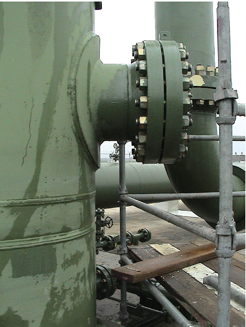
Figure 1. Bolted flange joints, such as those shown here, are a common sight at production sites
Introduction
Hot bolting is the procedure or practice of replacing bolts in a flange connection while the pipeline or equipment is still in service. This article focuses in particular on the required bolt force to be achieved during the re-tightening process. The criterion for the analysis is to ensure gasket pressure is maintained to a sufficient level during hot bolting to prevent leakage when the bolt load is reduced. The solution must account for the flexibility of the flange because the absence of a bolt increases the distance between applied bolts. The reduction in gasket stress will be largest at the point halfway between the bolts adjacent to the location of the removed bolt. The solution is based upon finding the bolt stress that must be present in the remaining bolts to satisfy the gasket pressure criterion. Moreover the resulting solution takes into account gasket pressure criterion, flange flexibility, internal pressure and flange loads.
Approach and assumptions
The approach requires that the stress in the gasket is sufficient to maintain a seal during hot bolting. It has been assumed that for hot bolting, the following circumstances hold:
- Only one bolt will be removed at a time
- The minimum gasket stress will occur in the circumferential midpoint of the gap left by the removed bolt
- The flanges in question conform to ASME B16.5 (Welding Neck Flanges) [1]
Therefore, the approach is based on the bolt stress requirement to achieve the appropriate gasket pressure.
Condition to be satisfied for “hot bolting.” During operation the residual pressure on the gasket must be “ m” times greater than the internal pressure in order to avoid the loss of contact between gasket and seats.
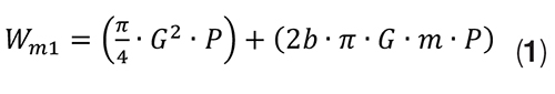
Gasket pressure criterion. The required gasket pressure should be taken from ASME BPVC Section VIII – Division 1 [2], where the bolt force to maintain gasket load under operating conditions is defined as W m1:
Where:
P = Internal pressure, MPa
G = Gasket reaction diameter, mm
b = Effective gasket width, mm
m = Gasket factor related to the minimum required load on the gasket for a tight joint, dimensionless
This force, Wm1, is composed of the hydrostatic end force due to internal pressure (πG2P/4) and the gasket joint contact load (2bπ GmP).
The term m is a factor specific to the type of gasket used in the joint. The value of m × P is the stress required in the gasket under operating conditions, and this should be used as the criterion.
In summary, there must be residual pressure on the gasket in order to keep it in contact with the flange surfaces, thus avoiding leakage. The seating force compresses the flanges against the gasket initially, the sealing force is equal to the bolt force. After pressuring the system, the residual pressure on the gasket is equal to the bolt force minus the separation force. The bolt force initially applied to the gasket must compensate for the separation force caused by internal pressure and be sufficient to maintain a residual stress on the gasket, avoiding fluid leakage. From a practical point, in order to maintain the sealing, the residual stress must be a factor m times the fluid pressure.
Flange flexibility
A method for predicting the ratio of gasket stress between bolts is taken from an article by Koves [3]. This stress ratio is a function of β × L, where L is the distance between bolts and β is defined by the dimensions and material properties of the flange and gasket.
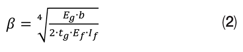
Where:
Eg = Elastic modulus of the gasket, MPa
b = Effective gasket width, mm
tg = Thickness of gasket, mm
Ef = Elastic modulus of flange, MPa
If = Second moment of area of flange, mm4
If = 0.0874 (Lc × go2 × ho × B)/Vc (for an integral flange with hub)
Lc = ASME VIII – 1 Code Appendix 2 parameter L, dimensionless
go = Small end of hub, mm
ho = ASME VIII – 1 Code Appendix 2 parameter, mm
B = Flange I.D., mm
Vc = ASME VIII – 1 Code Appendix 2 parameter V, dimensionless
L = Distance between bolts, mm
The Koves article [3] gives an equation which relates the ratio of gasket stress between bolts to β × L.
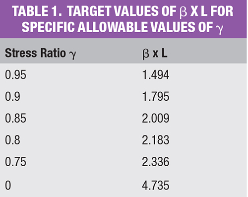
This equation is plotted in Figure 2 as a chart of β × L against stress ratio γ, whereas some target values of β × L for specific allowable values of γ are shown in Table 1.
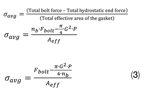
The solution relates the average gasket stress to the stress at the location of the missing bolt using the “Koves” stress ratio. The average gasket stress can be found using the net force over the area of the gasket. Consider the eight bolt flange in Figure 2 with one bolt removed. The average stress in the gasket, σavg, is a good estimate of the stress at the midpoint between A and B at the middle of the effective gasket width.
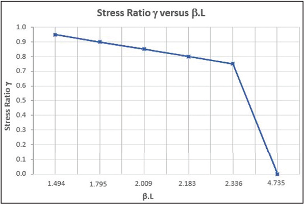
Figure 2. This graph shows a plot of the stress ratio γ versus β × L
Where:
Fbolt = Force from one bolt, N
G = Diameter of location of gasket load = GO – 2b, mm
P = Internal pressure, MPa
nb = Number of bolts, dimensionless
Aeff is the area of the gasket compressed by a bolt, which is:
(1/nb)×(π/4) × [GO2 – G 2], mm2
Atotal gasket = (π/4)[(O.D. gasket)2 – (I.D. gasket) 2]
= (π/4)[(O.D. gasket)2 – (O.D. gasket – 4b)2]
= (π/4)[(O.D. gasket)2 – (O.D. gasket)2 – 8 b × O.D. gasket + 16b2)]
= (π/4)(8 b × O.D. gasket – 8b × 2b)
= π × 2b (O.D. gasket – 2b)
Since O.D. gasket – 2b = G, the total gasket area is 2 bπ G
The latter is the same as the term in the Wm1 formula, Equation (1). Therefore, A eff = (1/nb) × 2 bπ G
GO = Effective gasket outer diameter, mm; with a maximum of O.D. contact face
A(eff/bolt) compressed by one bolt is: (1/nb) × Total effective area of the gasket (Aeff)
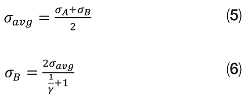
The “Koves” stress ratio, γ, gives the ratio of gasket stresses between B and A of Figure 3, but can also be used to find the stress at B using σ avg if it is assumed that σ avg is the average of the stresses at A and B.
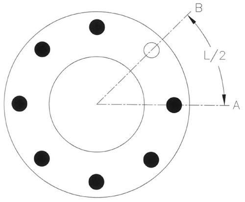
Figure 3. This diagram shows a flange face with one bolt missing at B
The goal is to find the required bolt force so that σavg is maintained in the gasket. Because a bolt has been removed, Fbolt still needs to be corrected as the total bolt force must be supplied by (nb – 1) bolts. Therefore:
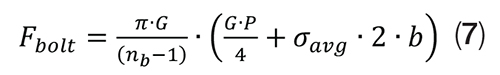
This criterion gives the required bolt force so that σavg is maintained in the gasket. If σ avg is set to the gasket pressure criterion Fbolt can be related to internal pressure for a specific joint. The properties of the joint being analyzed (materials, dimensions) are contained within the other terms in Equation (7).
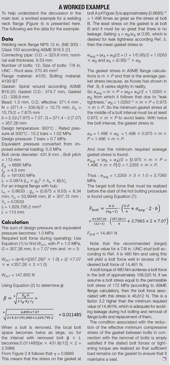
For the benefit of the user, a worked example has been added (box) in which the steps to be taken successively lead to a minimum required bolt force that must be present or applied before the bolt to be replaced may be removed.
External flange loads
Special consideration should be given to applications where flanges are subject to significant additional loading. Significant external loading is considered to be a combination of design pressure, external loads and external moments that, when converted to an equivalent pressure, Peq (defined below), are greater than 150% of the flange rated design pressure at design or operating temperature. Where external loading exceeds the 150% value, the designer shall consider the need for further evaluation based on known operating experience, consequences of a leak, conservatism of design loading, calculated percentage of flange rated pressure and other relevant influences.
P eq is defined as:
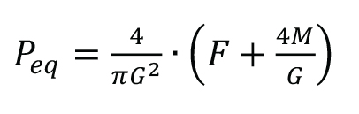
Where
Peq = Equivalent pressure due to external loading, MPa
G = Diameter at location of gasket load, mm
F = External axial tensile load on flange (ignoring compressive loads) for operating condition, N
M = Resultant external moment acting on flange for operating condition, N . mm
The flange design pressure becomes: Peq + P.
As an alternative, the following conservative approach may be used. If the magnitude of external loads is not known, this load can be approximated by doubling the internal (design) pressure. The background for this stems from the fact that the ratio between circumferential stress and longitudinal stress in the adjacent connected pipe is a factor of two. This corresponds to a doubling of the force of the adjacent cylindrical part.
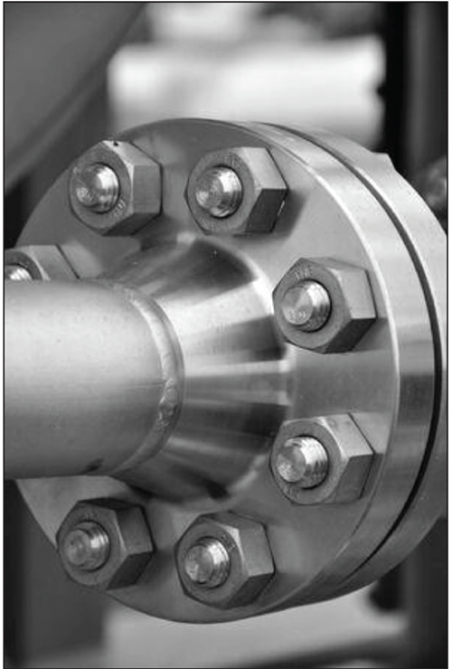
FIGURE 4. A typical welding neck flange is shown in this photo
Purpose of hot bolting
Hot bolting is the practice of removing and replacing or freeing and re-tightening bolts on live piping and equipment. It is potentially hazardous and the utmost caution needs to be exercised when planning and carrying it out. It is not recommended as best practice although it is widely carried out. However, any potential benefits arising from hot bolting should be carefully weighed against the risks encountered.
Considerations prior to hot bolting
When contemplating hot bolting, a number of factors need to be considered. These include, but are not limited to, the following:
- The operator’s own working procedures and guidelines
- The piping system and the system’s operating pressures and temperatures
- Flange joints considered for hot bolting should have a minimum of eight bolts. The bolt material should have a minimum strength equal to or greater than grades B7/2H
- Prior to the commencement of work, the site supervisor should review the maintenance history of the joint under consideration, and any joints of a similar type which have been hot bolted in the past. Is there any history that should be considered?
- The supervisor should also carry out a visual assessment of the joint. Hot bolting should not be carried out on joints that show significant signs of corrosion or necking, or which have worn or cracked threads on the fasteners
- Hot bolting should only be attempted under operating conditions when the history of the flange assembly is known, that is, records exist for the bolt load
- Hot bolting is not allowed at high temperatures (>300°C)
- The consequences of joint leakage during hot bolting should be considered (for example, toxicity, flammability and temperature of escaping fluids) and all necessary precautions taken. Contingency plans should also be put in place for an escape or emergency, for example, means of communications and provision of standby equipment
- Pipework within the vicinity of the joint to be hot bolted should also be reviewed. Pipe supports for the local section should be checked to ascertain whether they are taking the load on the pipe, along with their overall condition. If the pipework displays any significant signs of vibration around the specific flange, then hot bolting should not be considered as an option
Edited by Gerald Ondrey
References
1. ASME B16.5: 2017 “Pipe Flanges and Flanged Fittings”
2. ASME BPVC Section VIII – Division 1: 2019 “Rules for Construction of Pressure Vessels”
3. Koves. W. J., 2007, “Flange Joint Bolt Spacing Requirements,” Proceedings of 2007 ASME, Pressure Vessel and Piping Division Conference, PVP Vol. 3, pp. 3–10.
4. ASME PCC-1: 2019 “Guidelines for Pressure Boundary Bolted Flange Joint Assembly”
Author
 Walther Stikvoort is a consultant for pressure equipment and structural integrity (Address: Wagnerlaan 37, 9402 SH Assen, the Netherlands; Email: stikvoort@ziggo.nl). He started his professional career in 1969 with Continental Engineering, which formed a joint venture with M.W. Kellogg in 1972 to Kellogg Continental. He joined NAM (joint venture of Shell & ExxonMobil) mid 1985. Since his retirement from NAM in 2003, he has remained active for a period of 14 years as a consultant and expert for companies such as NRG and GLT PLUS. In his more than 50 years of employment, he has held various engineering and management positions in the petrochemical, fertilizer and oil-and-gas industries. He has initiated and developed many internal and external training courses and seminars focused on design aspects and integrity issues of pressure equipment for the benefit of the pressure equipment community. He was also an active member of several committees dealing with pressure equipment and structural integrity. Over the years, he has written more than 25 articles and/or presentations concerning static pressure equipment, as well as structural and mechanical integrity. Many of these have been published in open-access journals and technical magazines. The focus of Stikvoort’s entire career spanning more than 50 years has been on establishing and improving technical integrity and developing standards to achieve this and to disseminate his knowledge among his peers and other interested parties. His thorough theoretical knowledge and practical experience in his field is highly appreciated.
For additional articles on bolt loading, see “Standard ASME B16.5 Flanges: Bolt Tightening and Target Loads,” Chem. Eng., December 2019, pp. 38–42; and the online article, “Determination of Nozzle Loads to Facilitate the Initial Pressure Vessel Design,” October 26, 2018, which can be found at www.chemengonline.com.