This mature technology can be used to save energy, generate revenue and reduce emissions
With the Paris Agreement entering into force last November, the Parties to the Convention established their goals to implement measures to reduce the amount of greenhouse gas (GHG) emissions in order to combat climate change. The application of these measures in the chemical process industries (CPI) involves the study and employment of alternatives to improve energy efficiency and reduce emissions in an energy intensive sector.
Often in the CPI, a considerable amount of energy is wasted in pressure control valves, where high-pressure fluids must undergo a pressure reduction. Examples of this abound, such as gas sweetening (where the high-pressure rich amine stream is expanded to enter the low-pressure amine regenerator, and the lean amine is pumped back to the high-pressure absorber); gas dehydration (where the high-pressure rich glycol is expanded to enter the regenerator, and the lean glycol is pumped back); pipeline pressure-regulation stations; and others.
In these processes, a significant amount of energy can be recovered by employing hydraulic power-recovery turbines (HPRTs) where the fluid is incompressible (liquids), or expanders where the fluid is compressible (gases).
In these devices, the energy recovered in pressure reduction, which would otherwise be lost in throttling, is transformed to rotational mechanical energy, which can then be used to directly drive another rotating machine, or an electrical generator.
Even with low electricity prices, HPRT and expander technologies have advanced to a point where they represent reliable, economically feasible solutions to reduce power consumption and emissions from the CPI.
This article focuses on HPRTs — describing their main types and components, and summarizing how an operations manager, consultant or energy auditor in the CPI can assess the economic and environmental benefits of a potential HPRT installation.
HPRT characteristics
An HPRT is a machine that transforms an incompressible fluid’s hydraulic energy to mechanical energy, by reducing its pressure. The rotational mechanical energy can then be used to drive another rotating machine, or an electric generator.
In essence, an HPRT is very similar to a centrifugal pump working in reverse flow (that is, with fluid entering from the high-pressure nozzle, and being discharged from the low-pressure nozzle), and so is its mechanical design, with a runner being used instead of an impeller. In this regard, American Petroleum Institute standard API STD 610 [1] includes an appendix dedicated to those features for HPRTs that are different from those of a centrifugal pump.
HPRTs can be classified based on the configuration of their runners: overhung, between bearings or vertically suspended. Each type can be further classified depending on their couplings, number of stages, number of casings and geometry, as shown in Figure 1.
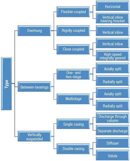
Figure 1. This chart shows the classification of different types of hydraulic power-recovery turbines (HPRTs)
Performance-wise, an HPRT compares with a pump as shown in Figure 2. The HPRT efficiency curve typically follows the same behavior of a centrifugal pump, with a maximum efficiency that is similar, or slightly higher than that of the equipment being used as a pump. HPRTs typically have a minimum flowrate requirement that is slightly higher than that of a centrifugal pump, below which the HPRT begins to consume power, rather than generate it.
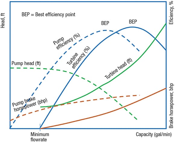
Figure 2. This graph shows the comparison of head, efficiency and horsepower curves between a pump and an HRPT
The HPRT efficiency curve can also vary depending on its internal geometry, as shown in Figure 3. For instance, by having a variable geometry, with guide vanes adjusting their angle depending on the flowrate, the efficiency of the HPRT is improved over the entire capacity range when compared with a fixed-geometry HPRT. One HPRT manufacturer also offers multiple inlet nozzles with flow distribution control, which, apart from widening the operating range of the HPRT, also “flattens” its efficiency curve, creating a “best efficiency range,” instead of a best efficiency point.
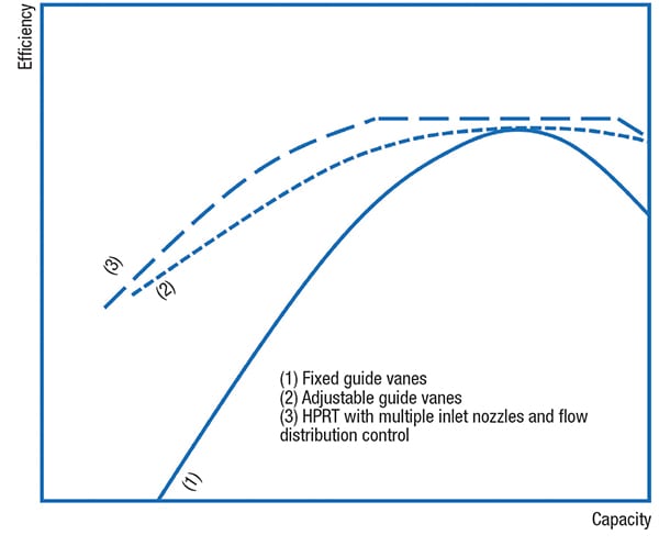
Figure 3. Shown here is the efficiency curve for three different HPRT
constructions

Figure 4. The arrangement of an HRPT with pump drive at motor speed is shown here

Figure 5. Shown here is the arrangement of an HPRT with pump drive at greater than motor speed
Fluid properties affect HPRT efficiency in the same manner as in centrifugal pumps, with higher-viscosity fluids reducing the efficiency. Some HPRTs tolerate flashing at their discharge, which greatly increases the power output.
HPRT process arrangement
The main HPRT equipment assembly includes the HPRT coupled to a generator or a pump.
When used to drive a pump, the HPRT is typically not used as standalone driver, but rather in a train arrangement where the HPRT and a motor act as dual drivers, with the pump drive rotating at the motor speed, or at a greater than motor speed, as shown in Figures 4 and 5, respectively.
When used to drive a generator, the mechanical assembly varies when coupled to a synchronous generator (which requires a governor to maintain a continuous rotation speed, synchronizing directly to the output voltage frequency), or an asynchronous generator (where the output voltage frequency is regulated by the power system to which the generator is connected).
An asynchronous generator has significant advantages when used in HPRT applications. These include relatively low cost; slip and overload capacities; and can more easily accommodate process variations, such as changes in flowrate, inlet and outlet pressure and fluid properties.
From a process point of view, a complete HPRT installation typically includes the components shown in Figure 6. This simplified scheme depicts an HPRT coupled to an asynchronous generator, with a variable-frequency drive (VFD) adjusting the output power characteristics to match those of the grid. Important components to ensure the operability and protection of the system include the following:
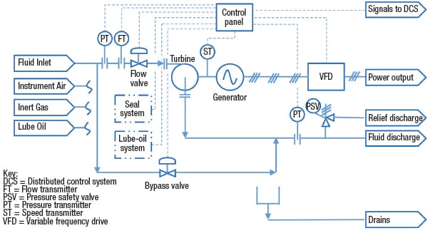
Figure 6. Shown here are the typical components used in an HPRT system (with inlet flow control)
Over-speed trip. This protects the equipment from an excessive speed derived from unexpected process conditions that could damage the equipment.
Throttle valve. The inlet flowrate is typically controlled by a throttle valve placed upstream, near the HPRT inlet, especially where gas evolution is expected, to allow for a larger power output. Some manufacturers prefer to locate the throttling valve downstream of the HPRT. Other manufacturers also offer multiple turbine inlet valves, where the flowrate added to each nozzle is controlled in order to maximize efficiency through a range of capacities.
Bypass valve. A modulating bypass valve sized for full flow is installed to allow for operational flexibility, if there is a contingency with the HPRT, and when the HPRT is taken out of service (for instance, for maintenance). Normally, the control between the turbine flow valve and the bypass valve is split range. When the HPRT is installed to replace an existing throttling valve, the latter can be left as a bypass, by making the necessary control adjustments.
Relief valve. A pressure safety valve (PSV) is also typically installed downstream of the HPRT to protect the low-pressure line and equipment.
Seal flushing system. A seal flushing system based on API STD 682 [2] is generally recommended for an HPRT. Some manufacturers present alternative assemblies, such as seal-less HPRTs.
Utilities. A typical HPRT arrangement also requires a lubricant-oil system, instrument air for pneumatic equipment, instrumentation and controls. It may also require inert gas, such as nitrogen, when handling flammable fluids.
Instruments and controls. Important variables to measure include inlet and discharge pressure, flowrate, rotational speed and power output.
HPRT process design
When preparing a request for quotation (RFQ) for an HPRT, the first step is to define and specify the service conditions to the manufacturer. These includes the following:
- Operating conditions (pumping temperature, flow, discharge pressure, suction pressure, differential pressure, differential head and hydraulic power)
- Design conditions (inlet and discharge design pressure, design temperature, rating and so on)
- Liquid properties (liquid relative density, vapor pressure, specific gravity and viscosity)
- The site and utility data (mounting location, electric area classification, site data such as elevation and atmospheric pressure, unusual conditions, and utility conditions, such as electricity, cooling water, instrument air and steam)
Also, a sketch of the installation, indicating whether the HPRT will be used to drive a rotating machine or be coupled to an electrical generator, is recommended, along with other electrical data (electrical area classification, type of generator, power output, voltage and frequency and so on).
Once the proposals have been received, the first step is to make sure that the data given to the bidders in the specification was used as input for the design.
Then, the customer can review the HPRT performance curve and predicted power output to check that the proposed equipment meets the service conditions. Ideally, an HPRT will be selected so that the operating point is near the best efficiency point (or “best efficiency range,” as offered by some manufacturers).
Care must be taken to ensure that the bidder reports electrical power at the generator terminals, as opposed to only brake power. If the bidder is reporting brake power, then the purchaser must deduct other mechanical and generator losses to compare with other bidders.
Other technical considerations to be taken into account when evaluating proposals include the following:
- Does the bidder offer a turn-key package (for example, a skid-mounted unit including the HPRT, generator, plus all the piping, valves, electrical, and instrumentation components), or only the equipment (for example, HPRT and generator)?
- Does the bidder offer a warranty for the entire system, or only for the HPRT?
- Can the proposed equipment handle predicted variations in fluid conditions, flowrates and properties?
- Can it handle solids (maximum particles size), vapors, corrosive, abrasive or other foreseen contaminants in the fluid?
- Does the proposed equipment meet the area classification and other safety requirements?
- Does the bidder offer technical support? Does it have online monitoring capabilities to assess equipment performance remotely?
- What other references for previous installations can the bidder provide?
- What are the maintenance requirements (for example, replacement of parts, recommendable spare parts stock and so on)?
- Other criteria, as applicable
Finally, an economic analysis should be performed on each alternative, in order to compare the return on investment of each option. A higher initial investment can be justified by a higher equipment efficiency, which in turn translates into more savings each year.
Economic benefits of an HPRT
The installation of an HPRT can be economically justified in many scenarios by savings in electrical power or fuel consumption, or by earnings from electricity sales to the grid. In some cases, the equipment payback period can be less than two years.
To calculate the savings (or earnings), the purchaser (or consultant) must first calculate the available hydraulic power that can be recovered in an HPRT, taking into account the fluid flowrates, properties and conditions, using the following equation:
![]() (1)
(1)
Where:
Whyd = HPRT hydraulic power, kW
Q = Flow capacity, m3/h
ρ = Fluid density at operating conditions, kg/m3
g = Acceleration due to gravity, 9.81 m/s2 at sea level
Δ h = Differential head, m
Or, in U.S. customary units:
![]() (2)
(2)
![]() (3)
(3)
Where:
hphyd = HPRT hydraulic power, hp
Qgpm = Flow capacity, gal/min
SG = Fluid specific gravity, unitless
DPpsi = Differential head, ft
Then, the hydraulic power is multiplied by the HPRT efficiency to obtain the brake power:
![]() (4)
(4)
Where:
Wbrake = HPRT brake power, kW
ηHPRT = HPRT efficiency, unitless
Typical HPRT efficiencies can be higher than 80% for water, and higher than 70% for other viscous fluids, such as petroleum.
If the HPRT is used to drive another piece of rotating equipment, the total energy savings is obtained by multiplying the HPRT brake power by the efficiency of the clutch, and other mechanical devices between the HPRT and the driven equipment. Additional electrical consumption from auxiliaries (control valves, instruments, control panel and so on) is also deduced to obtain the net power savings. The total saved energy in a year is obtained by multiplying this value by the number of running hours in a year.
![]() (5)
(5)
Where:
Esave,dr = Energy savings from HPRT as driver, kWh
ηclutch = Clutch efficiency, unitless
ηcoupled = Coupled equipment efficiency, unitless
Waux = Auxiliaries power consumption, kW
A = HPRT availability (Available running hours per year x 8,760 hours)
If the HPRT is used to generate electricity for the grid, the power output is obtained by multiplying the HPRT brake power by the efficiency of the generator. Additional electrical consumption from auxiliaries (control valves, instruments, control panel and so on), and losses in electrical equipment (VFD, switchgear, step-up transformer, power lines and so on) are also deduced to obtain the net power output. The total energy exported in a year is obtained by multiplying this value by the number of running hours in a year.
![]() (6)
(6)
Where:
Eexp = Energy exported to grid, kWh
ηgen = Generator efficiency, unitless
Waux = Auxiliaries power consumption, kW
Wloss = Power losses in electrical equipment and power lines, kW
Then, the savings (or revenues) can be calculated to assess the economic benefits.
When the power recovered by the HPRT is utilized at the same site (for example, in an amine regenerator, where the HPRT recovers power from the rich amine stream and drives the lean amine pump), the HPRT is economically justified by the savings in electrical consumption through the equipment life period (if the electricity is supplied by a utility or third party), or by the savings in fuel that would be burned to generate such electricity (if the facility generates its own electricity).
When the power recovered by the HPRT exceeds the local power needs (for example, in a pipeline pressure-regulation station), the excess power can be exported to the grid. In this case, the facility design would need to consider the local utility interconnection requirements, and any specific regulations and procedures applicable to cogeneration. Depending on the project specifics, the owner can then select to either feed the power to the grid in exchange for credits from the utility (as is the case with distributed generation), pay the utility a transmission and distribution charge so the power can be used at another owner’s facility (for instance, a pump station), or sign a power-purchase agreement (PPA) with the utility or another power consumer. The earnings in each case vary, depending on local regulations and market conditions.
Other incentives may apply as additional earnings, from either the implementation of energy efficient measures, or by emission reduction credits in emission markets.
An example calculation
To get an idea about the potential savings, an example calculation is provided here.
The problem. An HPRT is to be installed in a natural-gas sweetening plant, to replace the pressure let-down valve at the rich amine line to the regenerator. The HPRT will be used to drive an electrical generator, and the power will be fed to the plant electrical distribution system to supply power to local loads. The HPRT will handle 500 gal/min of fluid and a pressure drop of 1,000 psi. The efficiency of the selected HPRT is 75%, whereas the efficiency of the asynchronous generator and connected VFD are 95% and 98%, respectively. The HPRT will require an additional auxiliary load of 2 kW. The distribution system losses are not taken into consideration in the analysis. The plant manager wishes to calculate the savings in electrical energy in a year, considering that the HPRT will run 95% of the time, and the local electricity cost is $0.10/kWh.
The solution. Using Equation (2), the HPRT hydraulic power is:
hphyd = (500 gal/min x 1,000 psi) ÷ 1,715 = 292 hp
In kilowatts:
Whyd = 0.7457 x 292 hp = 217 kW
The HPRT brake power is:
Wbrake = 217 kW x 0.75 = 163 kW
The net energy output in a year is:
E exp = (163 kW x 0.95 X 0.98 – 2 kW) x 8,760 x 0.95 = 1,246,662 kWh
The net energy savings in a year are:
Annual energy savings = 1,246,662 kWh x $0.10/kWh = $124,666.
Environmental benefits
The environmental benefits of recovering electricity include, mainly, the reduction of emissions (carbon dioxide, carbon monoxide, oxides of nitrogen and sulfur, particulate matter) that is achieved when substituting energy that would otherwise be generated through the combustion of fossil fuels.
The amount of emissions reduced each year can be calculated by multiplying the amount of annual electricity savings by the emissions factor of the main power source in the facility.
The emissions factor varies for each technology type, location and fuel. Some calculation methods assume an average emission factor for a given technology and fuel (for example, gas-fueled combustion turbine, diesel-fueled reciprocating engine or others); whereas other methods are based on calculating the amount of fuel saved, and their composition (C, H, S, N). Some of these methods can be consulted from a number of references [3–6].
Concluding remarks
HPRTs are a mature technology, with several decades of application in different industries. Their principle of operation is similar to that in hydropower stations, and they can be reliable, technically and economically valuable options to reduce emissions while also securing important economic benefits for the CPI.
References
1. “API STD 610 Centrifugal Pumps for Petroleum, Petrochemical and Natural Gas Industries,” 11th edition, American Petroleum Institute, 2010.
2. “API STD 682 Pumps – Shaft Sealing Systems for Centrifugal and Rotary Pumps,” 4th edition, American Petroleum Institute, 2014.
3. “Compilation of Air Pollutant Emission Factors AP-42,” Fifth Edition, Volume I: Stationary Point and Area Sources. U.S. Environmental Protection Agency, 1995.
4. API, “Compendium of Greenhouse Gas Emissions Methodologies for the Oil and Gas Industry,” Final Draft. American Petroleum Institute, 2004.
5. “Petroleum Industry Guidelines for Reporting Greenhouse Gas Emissions,” International Petroleum Industry Environmental Conservation Association, 2003.
6. “Guidelines for the Measurement and Reporting of Emissions by direct participants in the U.K. Emissions Trading Scheme,” U.K. Department for Environment, Food and Rural Affairs, 2003.
7. Martin, Jeremy, Richter, Mark and Shirazi, Max, Application of a Hydraulic Turbogenerator in the Acid Gas Removal at a Gas Plant in the Middle East, 2016 Sour Oil & Gas Advanced Technology (SOGAT) conference, UAE, 2016.
8. Power Recovery Turbines. International Petroleum Industry Environmental Conservation Association, www.ipieca.org/energyefficiency/solutions/77721, Retrieved on 10/11/2016.
9. Adams, Ron, Reducing pressure – increasing efficiency, Sulzer Technical Review, 1/2011.
Authors
Sebastian o Giardinella is the vice president and co-owner of the Ecotek group of companies (Bldg. 239, 3rd floor, offices A and B, City of Knowledge, Panama City, Republic of Panama; Phone: +507 203 8490; Email: sgiardinella@ecotekgrp.com). He has experience in corporate management, project management, project engineering and process engineering consulting in projects for the chemical, petrochemical, petroleum-refining, oil-and-gas and electrical power-generation industries. He is a project management professional (PMP), has a M.Sc. in renewable energy development from Heriot-Watt University (Scotland), a Master’s Degree in project management from Universidad Latina de Panamá (Panama), and a degree in chemical engineering from Universidad Simón Bolívar (Venezuela). He has written technical publications for Chemical Engineering, international associations and academic institutions.
 Katherine Chung is a mechanical engineer at the Ecotek group of companies (same address as above; Email: kchung@ecotekgrp.com). She has over two years of experience in the preparation of mechanical equipment documents in conceptual, basic and detailed engineering projects for the petroleum-refining, oil-and-gas, power-generation and chemical industries. She is a mechanical engineer from the Universidad Tecnológica de Panamá (Panama).
 David López is the commercial director, environmental engineering specialist and co-owner of Ambitek Services, Inc. (Bldg. 231, 1st floor, City of Knowledge, Panama City, Republic of Panama; Phone: +507 317 0464; Email: dlopez@ambitek.com.pa). He has experience in project appraisals, from technical-financial prefeasibility, for new projects in environmental technology, water treatment, and energy efficiency; integral residue management, environmental indicators, ISO 9001 and 14001 certification, environmental impact assessment and environmental permitting. He is currently finishing a M.Sc. in renewable energy from Universidad Europea del Atlántico (Spain), has a M.B.A. with specialization in finance from Universidad Metropolitana (Venezuela), and is an environmental engineer from Universidad Católica Argentina (Argentina).
 Martín Ávila is the Mechanical Engineering Department chief at the Ecotek group of companies (same address as above; Email: mavila@ecotekgrp.com). He has over 30 years of experience in technical coordination and execution of projects for the power generation, oil-and-gas, petroleum-refining and general industries; specializing in mechanical (static and rotating) equipment design, specification, selection and QA/QC; with wide experience in power generation turbines. He has a specialization in gas engineering from Universidad del Zulia (Venezuela,), and mechanical engineering from Instituto Universitario Politécnico de las Fuerzas Armadas Nacionales (Venezuela).