Surprising observations regarding flooding in the upper fractionation trays of an atmospheric crude-petroleum distillation column are investigated
In industial distillation processes, flooding is an abnormal, but relatively common, process condition in which liquid accumulates in the column. The accumulation may be caused by excessive upward vapor flow, which results in massive entrainment, or by a restriction in the downcomers, impeding liquid downflow in the column. Flooding usually results in dramatically reduced separation efficiency, excessive pressure drops and sometimes instability. In many cases, the situation leading to flooding is complicated. Here, the authors present findings from an investigation of flooding in a distillation column at a petroleum refinery that revealed some surprising observations involving the loss of valve floats from the column trays.
Crude tower flooding
The investigation centered on an atmospheric crude tower that experienced severe corrosion in the top pumparound (TPA) and upper fractionation trays. The likely cause of the corrosion was the entry of small quantities of water, which hydrolyzed chlorides, forming HCl that caused extensive corrosion and damage to the 410 stainless-steel trays.
Pressure-drop measurements on the column showed flooding taking place both in the four-pass TPA trays and also in the two-pass fractionation trays below. After some time, the pressure drop decreased. A gamma scan after the pressure drop went down confirmed flooding in the upper three trays in the fractionation section. Upon shutdown and inspection, corrosion and damage were observed in the TPA trays, as expected. The surprise was that the upper trays in the fractionation section were found clean, but missing most of the valve floats. The missing valve floats were not found, and were probably washed away or corroded away. The absent valve floats increased the open area on the trays, and should have moved the trays further away from flood, but flooding was indeed observed. The flooding only occurred near the end of that run, and did not occur in the earlier runs, when the valve floats of these trays were found in place.
This raised the question: could losing the valve floats have promoted flood in the fractionation trays? To gain a better understanding of the observation, we analyzed plant data and applied a method we developed, known as the Fluor multipass maldistribution model (MMM), to determine whether these observations can be modelled. In a previous article [1], we applied the same model to discover multiple steady-state vapor/liquid distributions in two-pass moving-valve trays at turndown.
Due to the symmetry of two-pass trays, a perfect split of both vapor and liquid between the passes is always one possibility and a well known steady-state distribution. Our analysis shows that uneven float removal on the trays can alter the vapor and liquid flows through each pass, leading to premature flood, but that an even removal of the valves from each of the passes, as observed in this tower, would not lead to premature conventional flood.
Application of criteria for vapor cross-flow channeling (VCFC) showed that the most likely cause of the flood was the reduction in dry tray pressure drop upon valve pop-out, which induced VCFC. The VCFC led to premature flooding and efficiency loss. Related experiences showed that leaving tray manways unbolted can cause flooding when the loads are high and the conditions favor channeling.
Under most circumstances, the loss of valve floats is unlikely to cause flood. This is by far the more common case. However, when the loads are high and, at the same time, conditions favor channeling, loss of valves can lead to flood. Likewise, unbolted manways usually only lead to efficiency loss or instability, but not to flood. In the cases described here, the flood occurred because the towers operated at high loads and under conditions conducive to channeling.
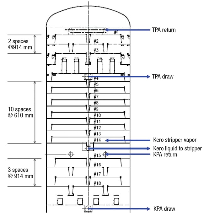
Figure 1. The diagram shows the internal geometry of the top section of the crude-petroleum distillation column
Tower history
The upper section in the tower (Figure 1) contains three TPA trays (Nos. 1 to 3), a chimney tray collector, and eleven naphtha-kerosene (N-K) fractionation trays (Nos. 4 to 14). The TPA is drawn from the chimney tray, cooled, and returned to tray 1. The remaining liquid from the chimney tray overflows through downcomers as reflux to the naphtha-kerosene fractionation section. Kerosene is drawn from a sump under tray 14 as a total drawoff and flows to the kerosene stripper. Vapor returning from the stripper enters the atmospheric tower above tray 14. Trays 15 to 18 are a kerosene pumparound (KPA).
Trays 1–14 are conventional round, uncaged moving-valve trays fabricated out of 410 stainless steel. The valve floats of each tray are 50% light valves and 50% heavy valves, in accordance with a common industry practice [1]. The valves on trays 15–18 (the KPA) are small-size fixed valves. The TPA and KPA trays are four-pass trays at 914 mm spacing, while trays 4 to 14 are two-pass trays at 610 mm spacing.
Historically, no fouling and only a limited amount of corrosion were observed near the top of the tower. In the 2015 turnaround, some corrosion was seen on the top tray. Most of the valve caps on tray 1 and many on trays 2 and 3 were blown off.
During the next run, conditions occurred beginning in April 2016 that are believed to have intensified the corrosion rate. Corrosion near the top of an atmospheric crude-petroleum tower is a common experience.
During early autumn 2016, the tower experienced high pressure drops in the TPA and N-K fractionation sections. By winter of the same year, the high pressure drops in both sections came down, but at the time the plant was experiencing difficulty achieving the desired naphtha product (according to ATSM Standard D86; 95% point). Gamma scans on trays 4 through 18 taken in January 2017 showed flooding in the upper fractionation trays 4–6.
This behavior would normally indicate some combination of corrosion, fouling and damage. An inspection of the tower in May 2017 showed surprising results: there appeared to be corrosion and corrosion damage, but little evidence of fouling. Along with the refinery owner/operator, we launched a joint study to closely understand the experience. This investigation led us to an unexpected phenomenon not previously reported. This article describes our troubleshooting and findings.
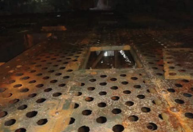
Figure 2. On tray 6 of the column, most of the floats were missing
Tray inspection
During a maintenance shutdown in May 2017, the tower was opened. The following observations were made:
- Many valves floats were missing on the top seven trays (for example, Figure 2). On trays 1 through 4, about 90% of the valve floats were missing. On trays 5 and 6, about 80% of the valve floats were missing, and on tray 7, 30% of the floats were missing. Some of the blown-off valve floats found had no legs, but most of the floats found had legs. The panels around the holes were corroded. The corrosion appeared to be uniform across the trays. It appears that the valve floats were blown off due to corrosion. One of the tray panels with missing valves is shown in Figure 2.
- Most of the missing floats could not be found. The inspectors checked the trays below trays 4 to 7 as well as the chimney trays, but could not find most of the missing floats. It appears that most of the floats were washed away or dissolved.
- Few valve floats were missing on trays 8 through 11. Hard rust was found on the tray floor between trays 8 and 11. However, these trays, as well as trays 12 through 16, were found in good shape without any irregularities.
- There was limited corrosion damage to the center and side downcomers from tray 3.
- On tray 4, a piece of tray panel (downcomer seal area) was detached.
- There was some foulant and scale on the trays, but not a large amount. There is a possibility that foulant could have been removed during shutdown, chemical decontamination and steam purge, but this is unlikely.
Vapor flowrate basis
In the following sections, as well as in Figures 3 and 4, the column internal vapor loads are expressed in m3/h of standard liquid. The internal vapor loads were calculated from plant instrumentation by mass balance. For instance, the vapor load at the top of the fractionation section, as well as at the bottom of the TPA, equals the overhead products flowrates plus the vapor condensed by the TPA. However, for hydraulic and flood calculations, internal vapor and liquid loads and physical properties were obtained from the refinery’s detailed simulation.
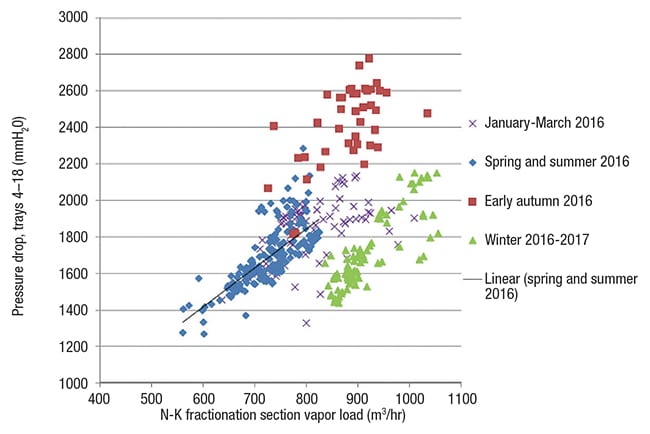
Figure 3. The plot shows the pressure drops in the N-K fractionation and the KPA sections of the column against vapor load in the N-K section
Analyzing pressure-drop data
The absence of apparent fouling led our investigation to closely examine the pressure drop data over the last 18 months of operation. Tower pressure drop was monitored between trays 2 and 3 in the TPA and between trays 4 and 18, which includes the naphtha-kero (N-K) fractionation section, as well as the KPA section.
Figure 3 shows that for trays 4 to 18 there were no signs of flood at loads as high as 1,000 m3/h in this section prior to March 2016. Flooding appears to initiate at a vapor load of about 750 m3/h in the autumn and even the summer data. Hydraulic calculations showed that with the trays intact, there should not be any flooding in the N-K fractionation section (trays 4 to 14). Using the Glitsch Equation [2] as recommended in Perry’s Handbook [ 3], we calculated the highest-loaded tray in this section to operate at 76% of jet flood and 56% downcomer backup (clear liquid) for the abnormally high vapor load of 990 m3/h, well above the vapor load at which the flood occurred. The FRI (Fractionation Research Inc.; Stillwater, Okla.; www.fri.org) jet flood correlation gave the higher value of 93% of jet flood for the same abnormally high vapor load, which also supports no flood. The pressure drop in the N-K fractionation section came right down by the start of the 2016–2017 winter, and at vapor flowrates below about 900 m3/h became even lower than during the period from January to March 2016.
Since the differential pressure measurement of trays 4 to 18 also includes the KPA section, it is necessary to address the possibility of the flood initiating there. Using the Glitsch Equation [ 2] as recommended in Perry’s Handbook [3], corrected for the small capacity enhancement of the small valves, we calculate the highest-loaded tray in the KPA section to operate at 92% of jet flood and 37% downcomer backup (clear liquid) for the abnormally high vapor load of 1,400 m3/h through this section. Figure 4 plots the pressure drop in this section against the KPA vapor load. The graph shows that the KPA vapor load at which the flood initiates is well below this 1,400 m3/h level; it is probably about 1,250 m3/h. Also, it shows that from January to March 2016, this section operated at vapor loads of 1,400 m3/h and even higher with no signs of flooding. With the KPA trays found completely clean at the turnaround, it can be concluded with confidence that the flood observed on trays 4 to 14 was a premature flood initiating in the upper fractionation section (trays 4 to 14) and not in the KPA.
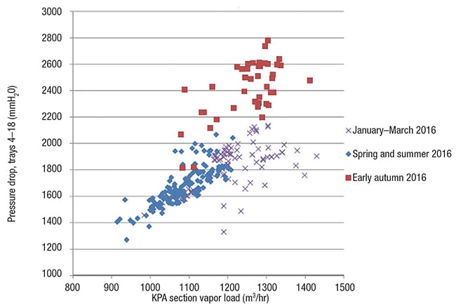
Figure 4. This plot shows the pressure drop in the N-K fractionation and KPA sections against vapor load in the KPA section
Pressure drop for the TPA section followed similar trends. Steady operation with normal pressure drops occurred during January to March 2016, slightly rising over the spring and summer. In early autumn, the pressure drops shot up dramatically, at vapor loads less than the previously experienced maximum. By the start of the 2016–2017 winter, the pressure drop fell, becoming even lower than it was from January to March 2016. Hydraulic calculations confirmed that with the trays intact, there should be no flooding in this section.
Historically, the naphtha product D86 95% point has run at 140–145˚C. There was no problem keeping the 95% point within this range throughout the spring, summer and even early autumn of 2016, although it appeared to move up slightly in the early autumn of 2016. In the winter of 2016–2017, however, the naphtha D86 95% point increased to more than 145–155˚C, indicating deterioration in tray efficiency in the N-K fractionation section.
Analysis of the differential pressure measurements indicates that during the early autumn and possibly earlier, salting out and corrosion products probably caused plugging of the TPA trays and of the upper fractionation trays below. This accounts for the high pressure drops observed during the early autumn. As time progressed, the corrosion products and salts were dissolved or washed away, and the plugging disappeared, causing the pressure drop to come down. The increase in open area on the TPA valve trays after the floats popped out caused the pressure drop in the winter of 2016–2017 to be less than when the floats were there. In the fractionation section, the same behavior occurred at lower vapor loads (below about 900 m3/h), but at higher vapor loads, the pressure drops were about the same as those observed when the floats were in place.
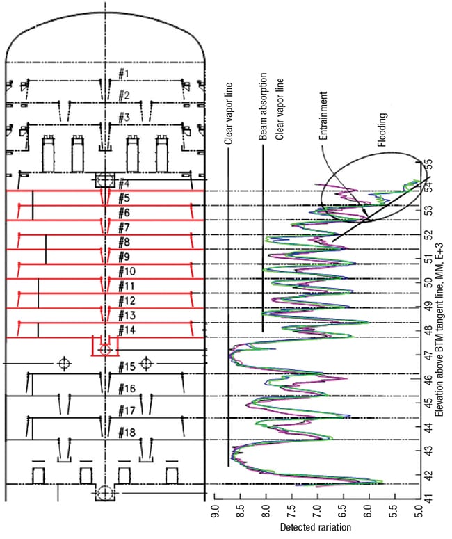
Figure 5. This diagram shows a gamma scan of the fractionation section of the crude distillation tower taken on January 17 and 18, 2017
Review of the gamma scans
The gamma scans (Figure 5) were conducted on the west side of the tower on January 17, with vapor loads in the N-K fractionation and TPA section at 900 m3/h, and on the east side of the tower on January 18, with the higher vapor loads of 990 m3/h in these sections. In Figure 5, the black and pink chords were shot on the west side at vapor loads of 900 m3/h. The blue and green chords were shot on the east side at vapor loads in the N-K fractionation and TPA of 990 m3/h. Since the east side was shot at a higher vapor load, any flooding is likely to appear more intense on the east, and any weeping is likely to be more intense on the west.
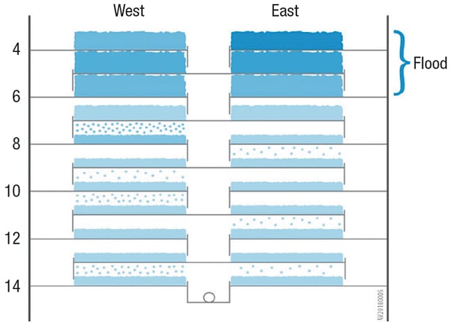
Figure 6. This “Kistergram” shows the tray froth heights and froth densities, as derived from the gamma scans
Figure 6 is a “Kistergram” [4], a graphic depicting gamma scan results on trays 4 through 14. Tray dimensions and froth heights are sketched to scale. The darkness reflects the froth density, with darker shades signifying denser froth.
Tray 4 was flooded. On the east side at the higher vapor load of 990 m3/h, the accumulated froth was particularly dense. The west side of this tray at the lower vapor load of 900 m3/h was flooded too, but as expected at the lower vapor load, with lower-density froth. Tray 5 was also flooded, again with froth accumulating on the east at the higher vapor load more dense than on the west at the lower vapor load. However, on both sides, the froths were less dense than that of those of tray 4 above. Tray 6 was also flooded, but here, the froth densities on the east and west sides were much the same and lower than those of the trays above. Tray 7 was not flooded on either side, and on the west side (at the lower vapor load), appeared to be weeping onto tray 6. The froth density was less than that of tray 5, and much the same as most of the trays below.
Trays 8 to 14 were not flooded. Their froth heights appear to have been about half of the tray spacing, and the froth densities were not high. This is similar to tray 7 above. Many trays showed liquid in their vapor spaces, but mostly only on the west side (at the lower vapor loads). This liquid is most likely weeping from the tray above, but entrainment cannot be ruled out as the cause. Distinguishing entrainment from weeping in these vapor spaces is difficult, although the observation of more liquid on the west vapor spaces (at the lower vapor loads) supports weeping. At the high vapor loads on both scan days (above 900 m3/h), weeping should have been low. Interference from the lattice support beams on the trays may have also impacted some of these radiation absorptions.
What can be stated with confidence is that flooding took place on trays 4 to 6, which were the trays with more than 80% of the float valves missing. The flooding was more intense at the higher vapor loads, causing denser liquid to accumulate on the east side scans. Trays 7 through 14 (which did not lose their valve floats) appeared to be operating more or less normally.
An observation not shown on Figure 6, but that can be seen in Figure 5, is that there was no flooding in the KPA section. The trays appeared well loaded and possibly entraining, but no flood. The vapor loads in the KPA were 1,275 and 1,370 m3/h on January 17 and 18, respectively.
One mystery raised by the gamma scan results is that trays 4–6 were flooded, but the pressure-drop data for trays 4 through 18 in Figure 3 did not support flooding on these dates. The pressure drop values measured for this section during the scans were 1,600 mm water (10 mbars per tray) on January 17 and 2,000 mm water (13 mbars per tray) on January 18.
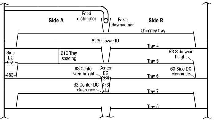
Figure 7. This diagram shows the key tray dimensions for the modeled column
Multipass maldistribution model
The tower modeled here is 8.23 meters in diameter, and contains two-pass sieve trays at 610 mm tray spacing. Tray dimensions, in mm, are shown in Figure 7. The open slot area with the valve floats in place is 10% of the active area, and the hole area of the valve holes with all the floats removed is 13.3% of the active area (not allowing for hole corrosion). Liquid to the top tray, and vapor to the bottom tray, were split equally between side A and B.
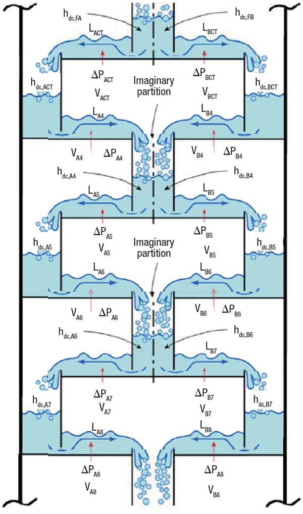
Figure 8. Here are key terms used in the multipass maldistribution model (MMM) equations
Two equalities are required for a hydraulically balanced distribution for two-pass trays (Figure 8):
1. Pressure drop. On trays with liquid flow from the center to the side, the center downcomer divides the vapor space, and the pressure on either side does not need to be equal. For trays with liquid flow from the side to the center, the vapor space is continuous, and the pressure equalizes in the shared space (that is, every two trays). For a balanced solution, the total pressure drop (through both trays) on either side of the shared downcomer must be equal.
2. Downcomer backup. As the center downcomer is shared, the calculated downcomer backup for either side must be equal.
All hydraulic equations are from the published literature and are the same as those in our earlier work [1]. For pressure-drop calculations, we used the Klein method [5] for valve trays, and the Summers and Cai sieve-tray pressure-drop correlation [6] for trays that had lost their valve floats. We used the Bolles and Fair method [7] for pressure losses through the tray aerated liquid. For downcomer backup, we used the classic downcomer backup equation in Perry’s Handbook [3].
All cases modeled used the same vapor and liquid loadings, which were those for tray 4 on January 18, 2017. Because these loadings are high, all light and heavy valves were open on each tray, so multiple steady-state vapor and liquid distributions based on valves opening and closing, as previously reported for turndown [1], were not plausible. Thus, for each case, the MMM resulted in only one possible allocation of vapor and liquid in the tray section, dictated by the geometry that was used.
Cases modeled
When describing each case, the following acronyms are used:
- CDC: center downcomer
- DCB: downcomer backup, expressed in clear liquid height divided by (tray spacing plus weir height)
- JF: percent jet flood, calculated using the FRI correlation
- L: percent of the total internal liquid flowrate
- V: percent of the internal vapor flowrate
Case 1, all valve floats in place. This case gave the expected performance of the intact trays. As the geometry is symmetrical, there is equal distribution of vapor and liquid for all trays in the section. The percent jet flood was 93% and 84%, respectively, for the center-to-side and side-to-center flow trays. The clear liquid backups in the side and center downcomers were 56% and 55%, respectively.
Case 2, valve floats missing per inspection. In this case, 90% of valve floats were missing on tray 4, 80% missing on trays 5 and 6, and 30% missing on tray 7. This situation increases the open area of tray 4 from 10.1% to 13.1%. The open area of trays 5 and 6 are increased to 12.6% and 12.7%, and the open area of tray 7 is increased to 11.0%. In the model, the geometry is symmetrical, so there is still equal distribution of vapor and liquid for all trays in the section.
The change in geometry from Case 1 to Case 2 caused flooding in the actual tower, as shown in Figure 6, but the hydraulic calculations showed no flood. Percent jet flood marginally rose, from 81 to 84%, on trays 4 and 6 (side-to-center flow) and from 93% to 94% on tray 5 (center-to-side flow). On tray 7, the jet flood decreased from 93% to 92%. The percent flood stays relatively the same despite the large increase in open area because with the valve floats missing, the tray is more similar to a sieve tray than a valve tray, and the hydraulic diameters of the holes/slots are much larger. The downcomer backup decreased by 3–9% for trays 4–7. We conclude that, based on conventional hydraulic calculations, the loss of valves would not explain the flooding observed on trays 4–6.
Cases 3 and 4, asymmetric valve loss. We explored whether the maldistribution resulting from losing valve floats asymmetrically could result in the flood patterns observed on trays 4–6. These cases also show the extent to which maldistribution propagates through the tray section. Here, we report the results for two of these cases. More detailed analysis and another case can be found in Ref. 16. In all modeled cases, asymmetric valve losses generated flooding patterns vastly different from that observed in the actual tower. We therefore conclude that an asymmetric valve loss is not the root cause of the flood observed on trays 4–6.
Our analysis precluded downcomer choke. The side downcomers are generously sized, and maldistribution could only increase downcomer inlet velocity to 0.31 ft/s, which is within the operable range for this service [3]. With a tighter downcomer design, maldistribution can lead to downcomer choke flood.
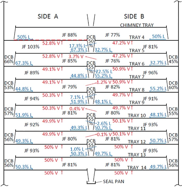
Figure 9. Case 3 of the modeling had 90% of the float valves missing on panel A of tray 4
Case 3, 90% of the valve floats are missing on panel A of tray 4, but all other valve floats are present. The hydraulic performance for this case is shown on Figure 9. The missing valve floats on panel A of tray 4 lead to a slight vapor maldistribution toward side A for trays 4 and 5 and a large liquid maldistribution toward side A for trays 5 and 6.
The loss of valves on panel A of tray 4 largely reduces the tray pressure drop and the downcomer backup on the A side of the imaginary partition in the CDC from tray 4. To equalize the backup, the CDC sends more liquid to panel A of tray 5. Because the backup is far more sensitive to the pressure-drop reduction due to the valve loss than to changes in liquid rate, a large increase in liquid rate is required to counter. Solution is achieved with a 67–33% liquid split to panels A and B of tray 5, respectively. The higher liquid load to panel A of tray 5 increases the pressure drop of this tray, countering the pressure drop imbalance across trays 4 and 5 and reducing the vapor maldistribution. The maldistributed liquid continues to tray 6. This time, it increases the backup on side A of the CDC from tray 6. To counter, this downcomer sends more liquid to panel B of tray 7. This change is far smaller in magnitude, making the liquid split 45–55% to panels A and B, respectively. Again, there is a minimal change in vapor distribution. The liquid maldistribution continues to zig-zag down the tower, each time at a reduced magnitude. By the time tray 10 is reached, it almost completely dissipates.
A key observation is that the pressure drop on these trays is far more sensitive to changes in vapor rate than to those in liquid rate, so there is a need to make large changes in liquid rate to make up for small changes in vapor rate. On the other hand, the downcomer backup is far more sensitive to the liquid flowrate.
The resulting rise of the percent jet flood from 93 to 103% and the downcomer backup from 56 to 66% (clear liquid) would likely flood tray 5, but on panel A only.
Case 4, 90% of the valve floats are missing on panel A of tray 4, and 80% are missing on panel A of tray 5. The hydraulic performance for this case is shown in Figure 10. For this case, the reduced dry pressure drop through panel A of trays 4 and 5 increases the fraction of total vapor flow to these panels. For Case 3, all valves were present on panel A of Tray 5, so the extent to which the vapor favored side A due to the lower pressure drop through panel A of tray 4 was limited by the greater pressure drop through panel A of tray 5. For Case 4, with 80% of the valves missing on panel A of Tray 5, the vapor favors side A to a much greater extent. With more vapor on side A, the dry pressure drop through either side of tray 4 is almost equal (a significant difference from Case 3). The result is a much smaller liquid imbalance, still favoring side A. Below tray 5, both the vapor and liquid imbalance completely dissipate. The rise of the percent jet flood from 93 to 109% would likely flood tray 5, but again, on panel A only.
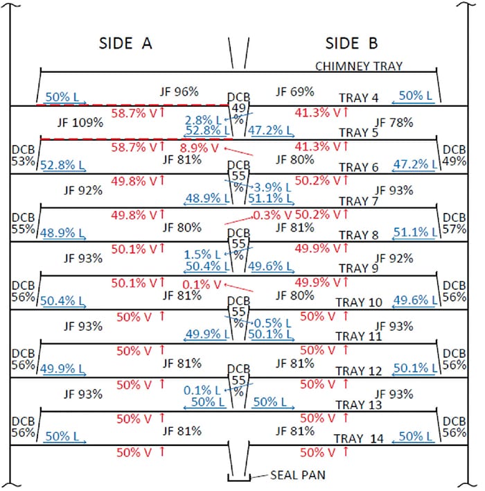
Figure 10. Case 4 of the modeling had 90% of the float valves missing on tray 4 and 80% missing on tray 5
Explanation of the tower flood
Our analysis shows that loss of valves can lead to flooding only if it occurs unevenly on the trays. However, the loss of valves observed in this tower has been even, similar to that modelled by Case 2. It can therefore be concluded that using the conventional flood equations, none of the cases modeled can explain the flooding observed on trays 4-6.
Our previous work showed that large open areas on trays can induce vapor channeling, such as vapor cross-flow channeling [8, 9], or other types [4, 10] of channeling. Such channeling generates high vapor velocity zones, accompanied by excessive entrainment and premature flooding, and high-liquid zones with excessive weeping.
For sieve and valve trays, the most common type of channeling, which is vapor cross flow channeling (VCFC), was shown to occur when the following four factors occur simultaneously:
- A high fractional hole area on the tray (greater than 11% of the active area with sieve trays, and greater than 13–14% of the active area with sharp-orifice valve trays)
- A ratio of liquid flowpath length to tray spacing above 2
- A weir load exceeding 50–60 m3/h m of outlet weir
- Pressure below 7 barg
In the N-K fractionation section of this tower, the ratio of flow path length to tray spacing is extremely high, more than 5.5:1. The liquid flowrate is in the VCFC range, a high, 96 m3/h m of outlet weir to the side downcomers and 50 m3/h m of outlet weir to the center downcomers, and the pressure is low (about 1 barg). The combination of these factors, especially with the long flow path length, is highly conducive to the onset of VCFC.
For as long as the valve floats were in place, the open slot area of the valves was about 10% of the active area, making them resistant to VCFC. Hartman [11] observed that at the high ratio of flow path length to tray spacing of 3.6, even sharp-orifice valve trays with about 13–14% open slot area can experience VCFC. With the higher ratio in this tower (5.5:1), it appears that the relatively low open area of these trays (10%) kept them well below the threshold of VCFC, thus protecting them from VCFC. However, once the valve floats were lost, the trays became sieve trays with about 13% open area, the trays entered the VCFC range. The onset of VCFC upon major valve loss was therefore the root cause of the premature flood, along with poor efficiency experienced in this section. VCFC leads to tray inlet weep [8,9], which is highly detrimental to tray efficiency.
Initially, when the trays experienced plugging or salting out, the pressure drop rose, signifying flooding, but there was not a great deal of efficiency loss, so the naphtha endpoint did not largely rise. Once the valve floats popped out, VCFC set in. The VCFC flood proceeds without a large increase in pressure drop, so the pressure drop decreased as it did in the late fall of 2016. However, this channeling induced large inlet weep that caused the tray efficiency of trays 4–6, and possibly 7, to drop significantly, causing the observed rise in naphtha endpoint.
Davis [12] explained the VCFC phenomenon as a force balance between the hydraulic gradient that tends to channel the vapor and the dry pressure drop that tends to evenly distribute the vapor. Davis proposed a rule of thumb that states that to prevent the onset of VCFC, the hydraulic gradient needs to be kept below 0.4 of the dry pressure drop. For the N-K fractionation trays, based on the January 18 loads, and the valve floats in place, we calculated a dry pressure drop of about 110 mm of liquid, and hydraulic gradients of about 50–60 mm. Once the valves popped out, the hydraulic gradients remained essentially the same, but the dry pressure drops were halved (to about 50 mm of liquid), which is about the same as the hydraulic gradients, and is in major violation of Davis’ criterion. It is certain that under these conditions, VCFC set in.
Related experiences
A colleague [14] of the authors brought to our attention some related experiences. In several towers, there have been experiences in which leaving the tray manways uninstalled led to flooding. He described one experience in particular. A 3-m, inner dia. chemical distillation tower operating at about 1 barg with 80 single-pass sieve trays at 460 mm tray spacing and weir loads of 80–90 m3/h m of weir length was returned to service after a routine turnaround in which no modifications to the trays were performed. The tray manways were dismantled for inspection but were not re-installed following the inspection. The tower flooded at 70% of the rated jet flood, which did not happen prior to the turnaround. The flood was recognized by excessive entrainment from the top of the tower, which doubled the measured reflux flowrate for the normal amount of reboiler steam. It was difficult to keep the level down in the reflux drum. Like in the crude tower, the pressure drop was normal. Not installing the manways can be expected to drop the tray efficiency, as it usually does, but increasing the open area can be expected to give the trays a larger margin from flooding.
As in the crude tower, the most likely explanation for the flood is channeling, in this case induced by the gap generated at the open manways rather than the hydraulic gradient. Again, all the conditions conducive to channeling (as described above) existed in the tower, except for the large open area. Once the manways were removed, the open area largely increased, causing channeling to set in and initiate premature flood.
Concluding remarks
The analysis reported in this article shows that loss of valves, or open manways, can lead to channeling, which in turn, can lead to premature flooding. Whether the channeling will result in flood depends on the operating rates and whether the tray geometry makes it prone to channeling. In the case described, it can be stated with confidence that the loss of valves led to VCFC, which in turn led to flood.
Under most circumstances, loss of valve floats is unlikely to cause flood. This is by far the more common experience. However, when the loads are high and at the same time, conditions favor channeling, loss of valves can lead to flood. Likewise, unbolted manways usually only lead to efficiency loss or instability but not to flood. In the cases described here, the flood occurred because the towers operated at high loads and under conditions conducive to channeling.
Our modeling work showed that for two-pass trays, an even loss of valves on both tray panels is unlikely to lead to flood in the absence of channeling. However, an uneven loss of valves on one of the panels is likely to move this panel closer to flood, and if the loads are high enough, initiate flood on the tray.
Finally, the study discussed here demonstrates that combining field data and gamma scans with hydraulic and maldistribution analysis using our recommended procedure [1,15] is a powerful tool for analyzing and diagnosing column problems. This approach has been successful for diagnosing and analyzing multipass tray maldistribution, unexpected efficiency loss at turndown, channeling, and uneven fouling.
Edited by Scott Jenkins
References
1. Olsson, M., and Kister, H.Z., “Can We Count on Good Turndown in Two-Pass Moving Valve Trays,” Chem. Eng. Progr., p. 43, November 2018.
2. Glitsch, Inc., Bulletin 4900, 6th Ed., Dallas, Texas, 1993.
3. Kister, H.Z., P. Mathias, D.E. Steinmeyer, W.R. Penney, V.S. Monical and J. R. Fair, “Equipment for Distillation, Gas Absorption, Phase Dispersion, and Phase Separation”, Sec. 14, in Perry and Green’s “Chemical Engineers’ Handbook,” 9th ed., 2018.
4. Kister, H.Z., Apply quantitative Gamma Scanning to High-Capacity trays, Chem. Eng. Progr., p. 45, April, 2013.
5. Klein, G.F., “Simplified Model Calculates Valve Tray Pressure Drop”, Chem. Eng., May 3, 1982, p. 81
6. Summers, D. R., and T. J. Cai, “Dry Tray Pressure Drop of Sieve Trays Revisited,” Chem. Eng., August 2017, p. 38.
7. Bolles, W., and J. R. Fair, in J. M. McKetta (Ed.) “Encyclopedia of Chemical Processing and Design”, vol. 16, p. 86, 1982.
8. Kister, H. Z., K. F. Larson, and P. E. Madsen, Vapor Cross Flow Channeling on Sieve Trays: Fact or Myth?, Chem. Eng. Progr., p.86, November 1992.
9. Kister, H. Z., Can Valve Trays Experience Vapor Cross Flow Channeling?, The Chemical Engineer, p.18, June 10, 1993.
10. Kister, H. Z., N. O’Shea, and D. Cronin, Loss into Gain in High-Capacity Trays Part 2: Reverse Vapor Cross flow Channeling, PTQ, p.27, Q3, 2016.
11. Hartman, E. L., New Millennium, Old Problems: Vapor Cross Flow Channeling on Valve Trays, in “Distillation 2001: Frontiers in a New Millennium,” Proceedings of Topical Conference, p. 108, AIChE Spring National Meeting, Houston, Texas, April 22–26, 2001.
12. Davies, J. A., Bubble Trays – Design and Layout, Pet. Ref. 29(8), p.93, 1950, and 29(9), p.121, 1950.
13. Kister, H. Z., “Is the Hydraulic Gradient on Sieve and Valve Trays Negligible?” Paper presented at the Topical Conference on Distillation, AIChE Meeting, Houston, Texas, 2012.
14. Olsson, F.R., Private communication, March, 2018.
15. Kister, H. Z., R. W. Dionne, W. J. Stupin, and M. Olsson, “Preventing Maldistribution in Multi Pass Trays,” Chem. Eng. Prog., April 2010, p. 32.
16. Olsson, M., and H. Z. Kister, “Can Loss of Valve Floats Lead to Premature Flood? Paper Presented at the Distillation Symposium, AIChE Spring Meeting, Orlando, Florida, April 22–26, 2018. Full copy is available from the author.
Authors
 Henry Z. Kister is a senior fellow and the director of fractionation technology at Fluor Corp. (3 Polaris Way, Aliso Viejo, Calif.; Phone: 949-349-4679; Email: henry.kister@fluor.com). He has over 30 years experience in design, troubleshooting, revamping, field consulting, control and startup of fractionation processes and equipment. Kister is the author of three books, the distillation equipment chapter in Perry’s Handbook, and over 100 articles, and has taught the IChemE-sponsored “Practical Distillation Technology” course more than 500 times in 26 countries. A recipient of several awards, Kister obtained his B.E. and M.E. degrees from the University of New South Wales in Australia. He is a Fellow of IChemE and AIChE, Member of the NAE, and serves on the FRI Technical Advisory and Design Practices Committees.
 Matthew Olsson was a part of the Distillation Expertise Team at Fluor Corp., in both Sugar Land, Tex., and Aliso Viejo, Calif. He has now moved to Eastman Chemical Co. in Longview, Tex., where he is a process design engineer. He has ten years of experience in design, troubleshooting and revamping fractionation processes and equipment. Olsson holds a B.S.Ch.E. from Texas A&M University in College Station, Tex.