Follow this guidance to specify a control valve accurately during the design phase
Control valves are one of the most common and important instruments used in the chemical process industries (CPI). They help to ensure smooth and efficient operation of process plants, by achieving the desired operating parameters by means of regulating the fluid flow in connected pipes. The need to properly specify control valves during the design phase of a plant cannot be overemphasized.
The size of a control valve is derived from a parameter called the flow coefficient ( C v), which is defined as volumetric flowrate (in gal/min) of water through the valve at 60°F when pressure drop across the valve is 1 psi ( C v is calculated using the formula given in the standard ISA-75.01.01-2007). Process engineers should take the following aspects into consideration when specifying control valves, to ensure that the valves that are manufactured by the vendors function according to the requirements.
1. Controllability. While specifying a control valve during the design phase, the process engineer should ensure that the valve’s controllability must be good over the entire range between minimum and maximum flowrates. This can be done by estimating the maximum C v and minimum C v that correspond to maximum flowrate and minimum flowrate, respectively. In general, the controllability of a control valve is deemed acceptable if its travel at maximum flowrate does not exceed 90% of the rated travel, and if travel at minimum flowrate is in the range of 10–20% of the rated travel. This means the ratio of estimated maximum C v to estimated minimum C v should preferably not be more than 15. If the ratio far exceeds this value, travel at minimum flow may be less than 10% of the rated travel, or the travel at maximum flow may be greater than 90% of the rated travel — both scenarios mean poor controllability of the valve. In that case, pressure drop across the control valve should be increased so that the target ratio can be lowered, as shown in Equation (1). For incompressible fluids, the ratio of maximum C v to minimum C v is given by Equation (1):
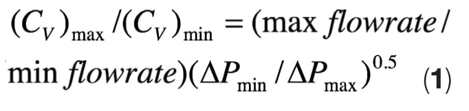
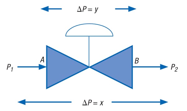
FIGURE 1. Shown here is a typical control valve circuit, which is used illustratively in the descriptions provided in the main text
Figure 1 shows a typical control valve circuit. The following notes add further explanation:
- The segments represented by P 1 Aand BP 2 represent items connected to the valve (such as pipes, fittings, heat exchangers, flow elements, and more), whereas the segment represented by AB represents the control valve in the complete circuit P 1 ABP 2. The arrows in this circuit represent flow direction.
- ∆ P denotes pressure drop.
- Indicated pressure drops are for maximum flow.
Referring to Figure 1, if x is the pressure drop across the control valve circuit P 1 ABP 2, and y is the pressure drop across the control valve AB for maximum flow, then the pressure drop in the remaining part of the circuit (consisting of the pipes, fittings, heat exchangers, flow elements and more; as represented by the segments P 1 A and BP 2) is x–y for maximum flow.
If r is the ratio of maximum to minimum flow, and z is the pressure drop across the circuit P 1 ABP 2 at minimum flow, then — ignoring the elevation difference between P 1 and P 2 — pressure drop in the part of the circuit other than the control valve (that is, P 1 A and BP 2) at minimum flow is approximately = (x–y)/r 2.
Pressure drop across the control valve AB at minimum flow is approximately:
![]()
From Equation (1) and Equation (2), ( C v) max /(C v) min is approximately:
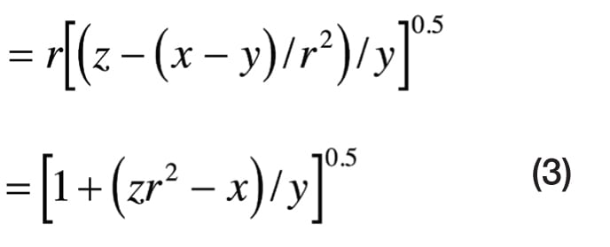
The following conclusions can be drawn from Equation (3):
- As r>1 and z≥x, any increase in y leads to decrease in the ratio ( C v) max /(C v) min. That is, better controllability can be achieved by increasing pressure drop across the control valve at maximum flow. (Note: z= x if P 1 and P 2 are fixed pressure points, and in general z> x if the control valve is located at the discharge of a centrifugal pump
- If r increases, y also increases for the same ratio of (C v) max to (C v) min. This means that pressure drop across the control valve at maximum flow should increase with an increase in the ratio of maximum to minimum flow, if the same controllability has to be achieved.
- In most common cases, maximum flow is 110%, and minimum flow is 50%, of normal flow. In such cases, if pressure drop across the circuit P 1 ABP 2 remains same for maximum and minimum flows, then Equation (3) becomes the following:
(C v) max /(C v) min is approximately = [1 + (3.84 x/ y)] 0.5, which implies that (C v) max /(C v) min is approximately 3.5, for an x/ yvalue of 3.0. A (C v) max /(C v) min value close to 3.5 corresponds to reasonably good controllability. Hence, it can be said that for good controllability, pressure drop across the control valve should be approximately one third of total dynamic pressure drop across the circuit at maximum flow, if maximum and minimum flow are 110% and 50%, respectively, of normal flow.
Although Equation (3) is true for incompressible fluid, the above results in general are reasonably true for compressible fluid, as well.
2. Cavitation. When fluid is flowing through a control valve, the minimum pressure occurs at the vena contracta, and then pressure increases along the path of flow until the fluid reaches the outlet of the control valve. The vena contracta is the point in the flow path where the flow area is minimum, the velocity is maximum and, hence, pressure is minimum [ 1]. For liquids, if the pressure at the vena contracta is less than the vapor pressure of the liquid, vapor bubbles will form. Downstream of the vena contracta, pressure recovery takes place, resulting in higher pressure at the valve outlet than at the vena contracta. If pressure at the outlet of the control valve exceeds the vapor pressure, the vapor condenses and bubbles collapse. As bubbles collapse, it causes impact on the valve body and creates noise. This phenomenon is called cavitation.
Full cavitation occurs when pressure drop across the control valve is more than or equal to certain minimum pressure drop (or critical pressure drop), and the pressure at the outlet of the control valve is more than the vapor pressure of the liquid. Thus, full cavitation occurs if the following conditions are met [ 2]:
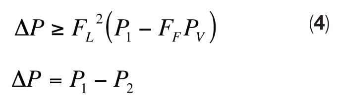
Where:
P 1 = Absolute pressure at the inlet of the control valve
P 2 = Absolute pressure at the outlet of the control valve
F L = Liquid pressure-recovery factor, as defined by:
![]()
P vc = Absolute pressure at the vena contracta
F F = Liquid critical pressure ratio factor
F F = 0.96–0.28 ( P v / P c) 0.5
P c = Absolute thermodynamic critical pressure of the liquid
P v = Absolute vapor pressure of the liquid at inlet temperature
The exact value of F L for a particular valve can only be available in the valve vendor’s specifiction sheet, but an indicative value can be obtained from the vendor catalog, from ISA-75.01.01-2007, or from other control valve literature during the design phase.
Process engineers should try to minimize the possibility of cavitation when specifying control valves. This can be done in the following ways:
- Alter the hydraulics of the control valve circuit and reduce the pressure drop across the control valve to less than F L 2 (P 1 —F F P V), where possible (as explained above), without compromising the controllability of the valve.
- Try to change the location of the control valve such that the possibility of flashing through the control valve can be avoided. For example, if a liquid is being heated in an exchanger in the control valve circuit, the control valve should be located upstream of the exchanger — not downstream — so that vapor pressure of the liquid is sufficiently less than the operating pressure at the vena contracta of the control valve. This will eliminate flashing through the control valve.
- Locate the control valve in the circuit where the elevation is minimum so that static head is maximum. This will maximize P 1 as well as P 2 without impacting ( P 1 – P 2). That can make the left-hand term in Equation (4) less than the right-hand term and, hence, prevent cavitation.
- Select a control valve body type with higher pressure-recovery factor ( F L), which makes critical pressure drop for cavitation — that is, F L 2 (P 1 —F F P V) — higher. For example, a globe valve has a higher F L than that of butterfly and ball valves. Thus, the use of a globe valve (instead of a butterfly or ball valve) might prevent the cavitation.
It is absolutely necessary to specify the thermodynamic critical pressure and vapor pressure of the liquid in the process datasheet of a control valve handling a liquid, so that the occurrence of the cavitation can be assessed. Full cavitation results in choked flow and happens if ∆ P ≥ F L 2 ( P 1 – F F P v). However, partial cavitation can occur without causing choked flow, if pressure drop is less than critical pressure drop but greater than ∆ P incipient cavitation [ 2],where:
∆ P incipient cavitation =

Where:
K c = The coefficient of incipient cavitation, which is less than F L [ 2].
3. Multiple operating cases.Whereas a control valve is generally specified for three cases — minimum, normal and maximum flowrates, with corresponding pressure drop — there may be more than three operating cases. In such situations, normal flowrate and corresponding pressure drop should be specified in accordance with the normal operating case, whereas other operating cases (if there are more than two) should be narrowed down to two cases. When narrowing down the operating cases, C v should be estimated for each case. Then, minimum and maximum flowrates (and corresponding pressure drops) should be specified in such a way that they correspond to the minimum and maximum C v of the control valve, and the C v corresponding to all other cases should lie between minimum C v and maximum C v. As actual C v is not available when a control valve is specified, the estimated C v should be used.
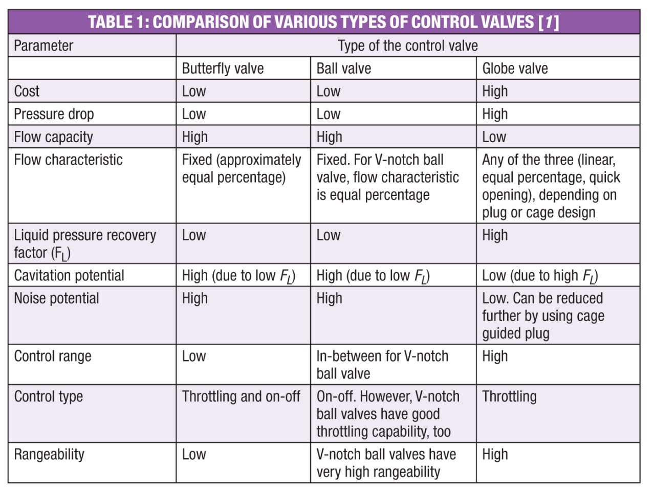
4. Selection of type of valve. Butterfly valves, which are compact and generally have a relatively low cost, are often the first choice. However, constraints may dictate otherwise. For instance, if high pressure drop across the valve is required, a globe valve may be the better choice. Because the resistance of a globe valve is higher than that of a butterfly valve, higher pressure drop can be obtained across a globe valve with reasonable size.
In liquid applications, high pressure drop could lead to cavitation. As the pressure-recovery factor of globe valves tends to be higher than that of other valve styles, cavitation can often be avoided with the use of globe valves.
In the case of gases, high pressure drop could lead to choking flow conditions, which can generate excessive noise. Noise can be minimized with a globe valve with the use of cage-guided trim. However, if the available pressure drop across the valve is low, then a butterfly valve may be the preferred choice.
Meanwhile, V-notch ball valves can be preferred where high rangeability is required. Standard, round-ported ball valves are generally used for on-off applications. Table 1 provides valve-selection guidelines.
5. Leakage class. The allowable control valve seat leakage is specified in terms of ANSI/FCI 70-02-2006 leakage class. This standard recognizes six classes of allowable seat leakage (Class I, II, III, IV, V and VI). Class I means highest allowable leakage; Class VI means least allowable leakage [ 3]. Generally, control valves for CPI applications are specified with leakage Class IV. However, in situations where tight shutoff is required, at least Class V should be specified. If a control valve is discharging to a flare, or is controlling (on-off) fuel flow to the burner of a fired heater or furnace, it should be specified with Class VI leakage.
6. Flow characteristics. The most common types of inherent flow characteristics are the following [ 1]:
- Linear — A valve with an ideal linear inherent flow characteristic produces a flowrate that is directly proportional to the amount of valve plug travel, throughout the travel range.
- Equal percentage — Ideally, for equal increments of valve plug travel, the change in flowrate regarding travel may be expressed as a constant percent of the flowrate at the time of the change.
- Quick opening — A valve with quick-opening flow characteristic provides a maximum change in flowrate at low travel rates. A quick-opening characteristic is basically linear through the first 40% of valve plug travel (corresponding to 70% of maximum flowrate), and there is little increase in flowrate with further increase in plug travel.
The flow characteristic of a valve depends on its trim design. While ball valves and butterfly valves have fixed characteristics, globe valves can have any of the three characteristics, depending on plug or cage design.
The type of flow characteristic should be specified in the process datasheet, considering the parameter to be controlled, or the pressure drop scenario in the system. For flow or level control, linear characteristic should generally be specified. In general, linear characteristic should also be specified if most of the pressure drop (as a proportion of total pressure drop in the system) is across the valve itself so that pressure drop across the valve remains nearly constant for varying flowrates. Equal-percentage characteristic should be specified for pressure control, or where a high proportion of the total pressure drop occurs in the system other than the valve (that is, in pipes, fittings, equipment and so on). It should also be specified where pressure drop across the valve varies with varying flowrate. A quick-opening characteristic should be specified for on-off applications. As in most of the common systems, pressure drop across the control valve varies significantly with flowrate, so equal-percentage flow characteristics are most commonly specified [ 1].
Edited by Suzanne Shelley
References
1. Emerson Process Management, “Control Valve Handbook,” 4th Ed., p. 18, pp. 33–36, p. 46, pp. 59–60, pp. 109–110, p. 136.
2. “Masoneilan Handbook for Control Valve Sizing,” 7th Ed., pp. 7–8, p. 10, 1987.
3. American National Standard, Control Valve Seat Leakage, ANSI/FCI 70-2-2006, Cleveland, Fluid Controls Institute, Inc., p. 2, 2006.
Author
 Satyendra Kumar Singh is the general manager (Head of Department) – Process for Simon India Limited (Mehtab House, A-36, Ground Floor, Mohan Co-operative Industrial Estate, New Delhi-110044, India; Email: sty_singh@yahoo.com; satyendra.singh@adventz.simonindia.com). He has more than 24 years of experience in engineering consultancy and engineering procurement construction in the fields of petroleum refining, petrochemicals, chemicals, oil-and-gas, and ammonia. Singh holds a Bachelor of Technology (Honors) degree in chemical technology from Harcourt Butler Technological Institute (Kanpur, India), and an Masters of Business Administration from Indira Gandhi National Open University (New Delhi, India). He is a Chartered Engineer (India), and a Fellow of The Institution of Engineers (India); and has published numerous papers on management and engineering subjects.