There are several technologies used in the disposal of landfill gas (LFG). Here are some key elements that can guide engineers in designing an optimized LFG processing plant
People generate trash. Trash is stored in landfills. Landfills contain bacteria, which decompose the trash to produce combustible landfill gas (LFG) [1]. LFG is a hazardous, flammable greenhouse gas containing mainly methane (CH4), along with many other components, including siloxanes, CO2 and mercaptans, as well as asphyxiants like hydrogen sulfide (H2S) and volatile organic compounds (VOCs). A detailed breakdown of typical LFG composition is given in Table 1. It also can be a valuable source of renewable energy.
If not disposed of properly, LFG can become an explosive and hazardous threat to nearby communities [2]. The minimum required disposal for LFG is incineration. This is typically used by smaller landfills, which do not generate enough LFG to produce a valuable volume of product. Direct-use methods, which are typically employed by medium- to large-size landfills, combust the LFG to take advantage of its heat content [3]. Electricity generation, cogeneration (cogen) of steam and electricity, boilers, kilns, iron forges and other thermal applications are typical direct-use applications.
Another method is conversion of LFG to pipeline-grade natural gas, which is sometimes used at large landfills. Pipeline-grade conversion is the most complicated of these methods, but could yield the greatest profit, depending on the price of natural gas. This article covers general design criteria and disposal methods used in the LFG industry. Various equipment and processing technologies, such as temperature-swing adsorption (TSA), pressure-swing adsorption (PSA), sulfur removal and thermal oxidization (TOX) are also discussed.
Consider economics
Economic analysis is the first step to select the best option from the available LFG disposal technologies (Figure 1). Plant economics are based on total LFG production during the peak production years of the landfill’s life (when the produced gas is around 55 vol.% CH4), usually from its fourth year to its fortieth year. Economic analysis must consider initial capital investment (capex) versus continued operational expenditures (opex). The size of the landfill is one factor to consider. Nearness to gas users is another factor. There may be little economic incentive to invest in a large, high-producing landfill if it is far away from energy-use infrastructure.
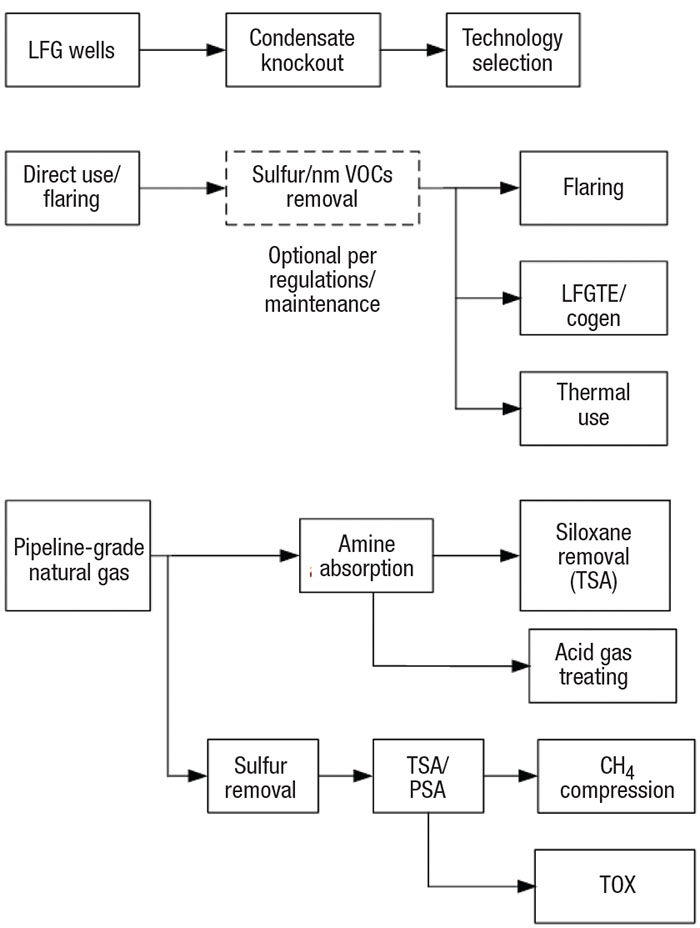
FIGURE 1. Landfill gas (LFG) can be handled using a number of technologies, depending on landfill size and economics
Flaring is usually considered by landfill operators who do not wish to risk capital investment. The economic break-even point is usually around 200 std. ft3/min of LFG during peak production. Landfills with high sulfur production may require additional investment to meet environmental regulations.
Many combustion-based direct-use technologies require a moderate capital investment. LFG used in kilns, boilers, LFG leachate evaporators and other burning technologies may not require any additional treatment if the operator is willing to spend more money on continued maintenance. LFG-to-electricity (LFGTE) production represents over 50% of the world’s direct use of LFG [ 3]. LFGTE projects typically generate 0.8 to 3 MW of energy, corresponding to approximately 200 to 750 std. ft3/min of LFG.
The profitability for purification of LFG to pipeline-grade natural gas is directly related to local spot prices.
LFG collection
LFG collection and condensate disposal design is the same for all LFG processes (Figure 2). LFG is drawn under low vacuum through underground wells and passes through a common header to a moisture separator. A blower transfers the LFG to the process, and a pump transfers the condensate to storage or back to the landfill.
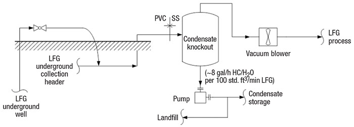
FIGURE 2. Condensate collection and disposal is an important consideration in LFG processing
LFG header and blower. LFG is collected through gas wells into a common header. The LFG is drawn to the LFG header based on the differential pressure between atmospheric pressure and the vacuum blower. On high-pressure days, more LFG is collected. Typically, the process engineer will design the LFG collection system to provide about 40 to 60 in. H 2 O vacuum at the suction of the blower [ 4]. The vacuum blower should be robust enough to handle gas with solid particles. A sliding-vane or liquid-ring blower is usually selected. Liquid-ring type blowers are much more expensive than sliding-vane, but they also provide improved reliability. Blower selection should consider capex versus opex.
LFG condensate knockout. LFG is collected at 100% relative humidity at about 140°F [4]. The warm LFG cools to about 90°F in the collection header, where some of the vapors condense. The condensate is separated in the LFG knockout vessel. LFG condensate is considered a hazardous waste because it contains halogenated organic compounds, sulfur compounds, aromatics and other aggressive chemicals that lower the pH to a range of about 4.2 to 5.0. The condensate collection header is usually designed with polyvinyl chloride (PVC), and the pipes and vessel metallurgy are usually stainless steel [5].
LFG condensate must not be drained to the sewer because it is a hazardous waste. It is either pumped back to the landfill or transferred to a hazardous-wastewater treatment facility. Condensate that is pumped back to the landfill is absorbed by the solid waste at the beginning of LFG production. Toward the end of its life, the landfill is saturated and the condensate must be treated as hazardous waste. At that time, the condensate is pumped to a polyethylene tank for storage and periodically transferred to a hazardous wastewater-treatment facility. Condensate contains both water and non-methane volatile organic compounds (nmVOCs). The nmVOCs could be as high as 0.6 mol% [1], or roughly 1 gal/h of hydrocarbon condensate per 100 std. ft3/min of LFG.
Water condensate is calculated as 100% relative humidity LFG cooled from 140°F to 90°F. The mass humidity ratio (x) is the ratio of the mass of water (mw) to the mass of dry LFG [6] (mLFG), and is used to calculate mass flowrate (ṁ) of condensate as defined in Equation (1):
ṁcond = ṁLFG (x140º F – x90º F) (1)
This shows that the condensate mass flowrate is roughly 7 gal/h of water for every 100 std. ft3/min of LFG. The pumps are specified as low-flow positive-displacement pumps at continuous operation. These pumps are typically diaphragm-type with non-metallic internals.
LFG flaring
The minimum-effort form of LFG disposal is to incinerate the gas [7]. Smaller landfills do not produce enough high-value LFG to justify the investment for more expensive, yet potentially profitable, processing.
There are two types of flares: simple candle-type flares and the more expensive enclosed flares. Typically, environmental regulations require 95% or greater destruction and removal efficiency (DRE) of CH4. The industry is moving away from candle flares because the temperature cannot be controlled enough to achieve the required DRE. An enclosed flare is a large vertical cylinder with multiple burners, temperature monitoring, air and fuel controls and heat conservation from refractory-lined walls. This design develops the maximum possible heat within the flare column.
Several factors (age of landfill, quantity of organic material, moisture, temperature and others) affect the quantity of LFG produced, as well as the composition of the LFG. At the beginning of the landfill’s life, the composition is approximately 3 mol% CH 4 and 97 mol% CO2, at 30 Btu/std. ft3. Toward the end of its life, less LFG is produced, but at a better lower heating value (LHV) of 550 Btu/std. ft3 (corresponding to 55 mol% CH4 and 45 mol% CO2).
Usually, enclosed flares are vendor-supplied and not designed by the process engineer. However, the process engineer should specify a maximum and minimum LFG flowrate, as well as a range of LFG compositions.
The process engineer should also ensure that flare systems are designed with auxiliary fuel injection to maintain the required DRE at the beginning of the landfill’s life. The flare stack should also be designed with burner tips that can be plugged, as well as adjustable air dampers, which maintain the DRE at the end of the landfill’s life.
It should be noted that in most locations, removal of sulfur and nmVOCs is not required prior to flaring or direct use [7]. The requirement for removal is a function of the concentration of these substances, direct-user gas specifications and local regulations.
Direct-use methods and LFGTE
Combustion of LFG provides a great deal of heat duty for boilers, steam and electricity cogeneration and gas turbines, among other technologies. Most of the world’s LFG direct use is electricity generation (LFGTE) [3].
LFG generator efficiencies are typically less than 40% because of the lower heating values of LFG compared to natural gas (around 550 Btu/std. ft3 versus around 1,000 Btu/std. ft3). High-efficiency generators can produce up to 400 kW per 100 std. ft3/min of LFG.
LFG generator motors are susceptible to increased wear because, unlike natural gas, many LFG components can create hard deposits on the engine’s pistons, cylinder heads, spark plugs and other motor parts. Siloxane, sulfur and halogenated hydrocarbons all can have a negative impact on the motor, as well as possibly exceed local regulations.
Pretreatment of the LFG and regular maintenance will prevent decreased engine life and performance. However, the process engineer’s capex versus opex analysis could consider that more frequent engine maintenance may be acceptable as a substitute for a siloxane removal system.
Siloxane and water removal
Siloxanes are a type of silicone polymer, and when present in LFG, cause severe mechanical problems in the internal combustion engines of the generators. Silicon dioxide is the main siloxane combustion product, and it causes deposits of hard scale. Worse yet, landfills with metal content (such as iron or aluminum) will form hard, glass-like silicate deposits. These deposits significantly reduce the engine’s life and significantly increase downtime due to maintenance. A common technology to remove siloxanes is temperature swing adsorption (TSA). In some cases, TSA units can be designed by process engineers, but they are usually vendor-supplied packages. Ref. 6 details the complete procedures for designing TSA units.
TSA systems (Figure 3) comprise two or more vessels (TSA beds) in parallel (one online for adsorption and the other offline for high-temperature regeneration), a regeneration blower and a heater. LFG passes through the adsorbent bed of the online vessel in downflow during the adsorption step. At the end of the adsorption step, the valves switch to set the offline vessel to online for adsorption and set the online vessel offline for regeneration.
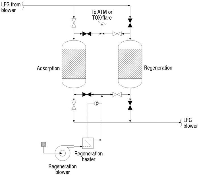
FIGURE 3. Temperature-swing adsorption (TSA) beds are used to remove water and siloxane content from LFG
In the regeneration step, hot regeneration gas (usually heated air) is blown through the adsorbent bed in an upflow pattern to swing the bed temperature, thus releasing the adsorbed siloxanes and water. Depending on local environmental regulations, the regeneration gas is vented, preferably to a thermal oxidizer (TOX). Industry experience suggests heating the adsorbent to about 400°F with 450°F gas. After the adsorbent has been regenerated, cool gas passes over the adsorbent to swing down the temperature to 100°F. The preferred adsorbent temperature is about 75°F or lower.
TSA adsorbents. The top adsorbent layer of the TSA bed is typically activated alumina or a molecular sieve for water removal, and the lower layer is silica gel for siloxane removal. Activated carbon was used for many years for siloxane removal. Now, however, the industry is using silica gel adsorbent because it has been demonstrated as the better siloxane adsorbent [8]. Activated alumina or molecular sieves are typical adsorbents for moisture adsorption. These allow silica gel (an excellent desiccant) to adsorb siloxanes selectively over water.
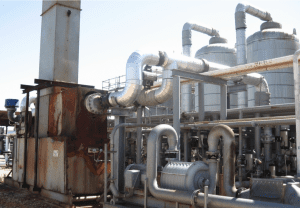
This TSA unit shows, from left: regeneration blower, regeneration heater, process blower, switching valves and TSA beds (back)
Adsorbent vessels are specified with a low length-to-diameter ratio to operate within a balance between a low pressure drop and minimum mass flux. The standard maximum pressure drop should not exceed 0.33 psi/ft across the bed. A low overall ∆P across the bed ensures that the adsorbent particles are not crushed.
The minimum mass flux across the bed should exhibit a particle Reynolds number (ReP) greater than 25. The high ReP ensures adequate turbulence for best adsorbent effectiveness. The total quantity of each adsorbent required is calculated based on the total mass of water and siloxane to be removed against the adsorption capacity and saturation-zone efficiency of each media. TSA dryers are designed to lower the dew point to –40°F. Industry experience indicates that about 8 lb of water are adsorbed per 100 lb of fresh activated alumina, and about 4 lb/100 lb after 4 years. About 1 lb of siloxane is adsorbed per 100 lb of silica gel.
Typically, siloxane concentration can be estimated at a conservative 2,000 to 3,000 ppmw. However, the actual concentration should be determined by gas analysis. Note that while there are techniques to analyze the siloxane concentration, there is no standard testing method.
Theoretically, adsorbent layers are divided into a saturation zone at the top of the bed and a mass transfer zone below. The mass transfer zone is the layer of the bed where the water and siloxane are adsorbed, and the saturation zone is the layer where the adsorbent is fully loaded. As water and siloxane are adsorbed, the saturation zone increases and the mass transfer zone “moves” down the bed. The repeated cycle of adsorption and regeneration throughout the life of the bed reduces the adsorbent efficiency.
LFG to pipeline-grade natural gas
Processes that convert LFG to pipeline-grade natural gas are complex and require high-purity product. Purification requires compression of the LFG, then removal of moisture, siloxanes, CO2 and inert substances.
Pipeline-grade natural gas characteristics are specified by local utilities. These specifications typically require that LFG be compressed to greater than 200 psig, and the CH 4 concentration must meet the heating value of about 1,000 Btu/std. ft3. The total inert gases should not exceed 4 mol%. The gas must be free of all siloxanes, solids and impurities. H2S must be limited to 4 ppmv and total sulfur (including H2S) must be limited to 12 ppmv. A TSA removes siloxane and moisture. Acid-gas treating and pressure swing adsorption (PSA) are two common processes for CO2 and sulfur removal.
In the acid-gas LFG purification process, a solvent is continuously circulated (Figure 4) through an absorber column and a regenerator column. Low-temperature lean solvent treats high-pressure acid gas in the absorber, and high-temperature, low-pressure rich solvent releases the concentrated acid gas to sulfur treatment.
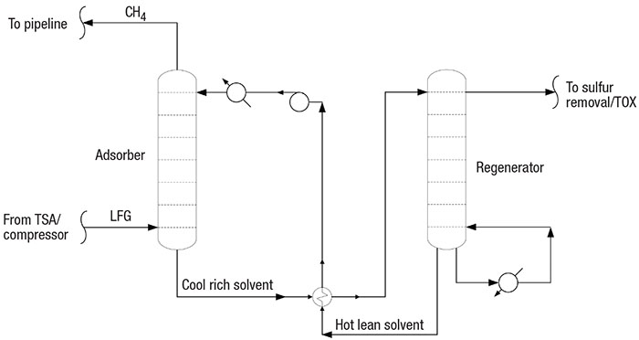
FIGURE 4. A solvent-circulation step treats the LFG’s acid-gas content
The PSA LFG purification process (Figure 5) is a batch-wise, high-pressure adsorption of CO2 on a PSA bed. The pressure swings low in the PSA bed to release the CO2.
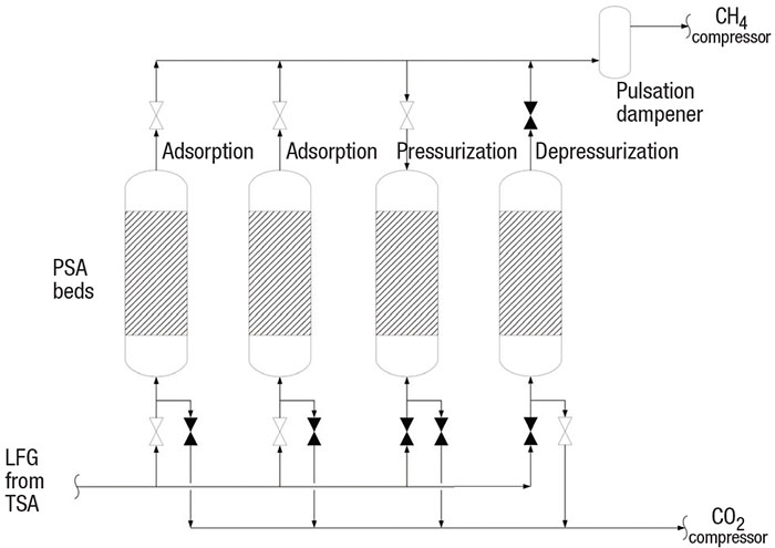
FIGURE 5. PSA units are used to absorb carbon dioxide from the LFG stream
Sulfur removal. One common technology used for sulfur removal is the adsorption of sulfur species on iron oxide, activated alumina or another porous metal catalyst. Adsorption units typically consist of two or more beds operated in parallel. Once sulfur nears its breakthrough point, the adsorption media is replaced. The media is then treated as hazardous waste.
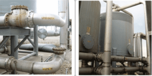
A typical catalytic H2S adsorber system is shown
Wet scrubbing, another sulfur-removal technology, is typically vendor-supplied and proprietary. Wet scrubbing chemically transforms the H2S and mercaptans into elemental sulfur. The LFG stream is contacted with an aqueous iron chelate solution, where the sulfur is ionized into hydrogen and sulfide ions [9].
The chelate complex is regenerated by oxidation and is returned to the absorber. The elemental sulfur can be sold to the fertilizer industry.
LFG compression and dewpoint depression. Sulfur-free LFG at 100% relative humidity should be chilled to 40°F (Figure 6). The chilled LFG is then compressed by a vendor-supplied compressor. Chilling the LFG to 40°F upstream of the compressor serves a dual purpose. First, any remaining aggressive condensate is knocked out for increased reliability of the compressor. Second, lower temperatures decrease the horsepower required by the compressor.
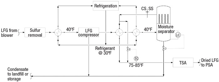
FIGURE 6. LFG is chilled to help remove any remaining condensate, and also to relieve the power load on the compressor
Hot, high-pressure LFG from the compressor should be chilled and dried through a coalescing moisture separator (or similar) to 40°F dewpoint. Typically, these separators experience a pressure drop of less than 20 in. H2O. The condensed moisture is blown down by on-off level control at high or low liquid levels.
The cold, dried LFG is warmed against hot LFG from the compressor. A temperature-control bypass valve is sized for about 30 to 40% of the total flow. About 75°F (or lower) is the preferred temperature range for TSA adsorbents. At the outlet of the moisture separator, the metallurgy can be downgraded from stainless steel to carbon steel [5].
CH4 and CO2 are separated in the PSA by adsorption of CO2 from high-pressure LFG. The PSA vendor specifies the minimum required pressure (typically 120 psig) to achieve >99% CH4 in the pipeline gas.
Blowcase operation. As discussed, the LFG from the blower is chilled to 40°F upstream of the compressor. This condenses the majority of the humidity (roughly 2 gal/h per 100 std. ft3/min), which collects in the compressor knockout drum. One control strategy for condensate disposal is to pump the condensate to the landfill or storage via on-off level control at high or low liquid levels.
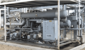
LFG must be chilled to prepare it for its final use
Another strategy is to collect the liquid in a small vessel called a blowcase and blow it down using on-off level control (Figure 7). During normal operation, the knockout-drum drain valve to the blowcase is open and the blowdown valves are closed. At the blowcase high-level signal, the inlet valve is closed and the blowdown valves are opened. The condensate is blown down with compressed LFG. At low liquid-level signal, the blowdown valves are closed and the drain valve is opened, which depressurizes the blowcase to the knockout drum. The process engineer should consider slow-opening valves to limit the blowdown rate and the impact of pressurization. The engineer must design the blowcase for cyclic service, because of the repeated operation of pressurization and depressurization.
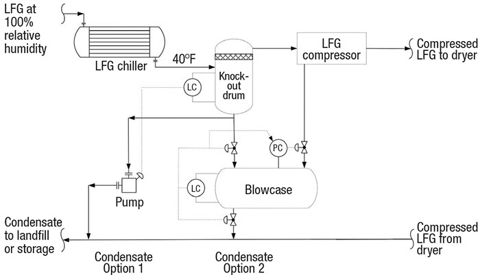
FIGURE 7. Larger LFG plants may use a blowcase configuration to help collect liquid
Solvent absorption. In the acid-gas LFG purification process, high-pressure LFG contacts a low-temperature amine (or other solvent) in an absorber column. Lean solvent absorbs moisture, CO2, sulfur and inert gases from the LFG. Rich solvent passes to a low-pressure, high-temperature regenerator, which separates the absorbed CO2 and sulfur. The lean solvent is circulated through the absorber, and the acid gas passes to a sulfur treatment process. Note that siloxane is not absorbed.
Methane recovery with PSA. A PSA system (Figure 5) operates on the same principle of adsorption and desorption as the TSA. However, the PSA adsorbs at high pressure and releases at low pressure. In a PSA, the smaller molecules are adsorbed and the larger molecules pass through the beds. Methane is a larger molecule (3.8 Å) compared with nitrogen (3.6 Å), O2 (3.5 Å), CO2 (3.4 Å) and water (3.0 Å). Zeolite 13X (a crystalline polymer) with a pore size of 3.7 Å is usually selected by the PSA vendor to adsorb the inert substances and pass the methane to the pipeline.
The PSA unit is a complex vendor package with a sequence of switching valves that control the pressurization, depressurization and adsorption steps (Figure 5). The PSA beds’ valves open and close to control the steps at each bed. In the depressurization step, the vessel inlet valve and the CH4 compressor’s suction valve close. Then the suction valve to the CO2 vacuum compressor opens. The very low pressure regenerates the bed by releasing all inerts adsorbed on the media. In the pressurization step, the inlet valve and compressor suction valve close and the outlet valve opens. This floods the bed with high-purity CH4. Once pressured, the inlet valve opens and the adsorption step begins.
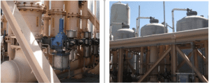
These PSA units are shown with switching valves, beds and pulsation dampener
The process engineer should specify the PSA system for at least 97% CH4 purity (based on local utility requirements) and 85% recovery. PSA technology can achieve greater than >99% purity and 95% recovery. The natural gas from the PSA should be compressed to pipeline requirements, typically 200 psig or greater, also based on localutility requirements.
CO2 destruction by thermal oxidation. PSA depressurization releases inert gases and 4 to 10% CH4. Environmental regulations typically do not allow release of these inert gases and CH4 to atmosphere. This low-BTU gas is then destroyed in a very high-temperature thermal oxidizer (TOX), which is also complex and typically supplied as a vendor package. The TOX operates under a similar principle as a high-temperature enclosed flare. The TOX burns the CH4 at very high DRE to meet environmental regulations. A very high combustion temperature is required because the high concentration of CO2 significantly decreases the DRE of CH4.
In poorly designed or poorly operating TSA systems, some liquid may remain in the LFG and thus may be adsorbed in the PSA. To capture the liquid droplets and prevent fireballs in the TOX, a pulsation dampener (as shown in Figure 5) should be considered. Any remaining water is adsorbed in the PSA. Liquid droplets are knocked out in the pulsation dampener, which should be sized for droplets in the range of 300 to 600 μm in diameter [11]. Because the PSA depressurization steps are not continuous, a pulsation dampener reduces the high surge of CO2 to the TOX at the start of the depressurization step.
Edited by Mary Page Bailey
References
1. Agency for Toxic Substances & Disease Registry, Landfill Gas Primer, U.S. Department of Health and Human Services, Nov. 2001.
2. U.S. Code of Federal Regulations, Title 40 — Protection of Environment, Part 258 — Criteria for Municipal Solid Waste Landfills, July 2012.
3. Arnold, M., Reduction and monitoring of biogas trace compounds, VTT Technical Research Centre of Finland, Aug. 2009.
4. U.S. Army Corps of Engineers, Landfill Off-Gas Collection and Treatment Systems, Department Of The Army, EM 1110-1-4016, May 2008.
5. Hansen, D.A., Puyear, R.B., “Materials Selection for Hydrocarbon and Chemical Plants,” CRC Press, 1st edition, Aug. 1996.
6. Gas Processors Suppliers Association, Engineering Data Book, 12th edition, 2004.
7. Scottish Environment Protection Agency (SEPA), Guidance on Landfill Gas Flaring, Nov. 2002.
8. Schweigkofler, M., Niessner, R., Removal of siloxanes in biogases, Journal of Hazardous Materials., 2001.
9. Wang, L.K., Pereira, N.C., Hung, Y.T., “Handbook of Environmental Engineering, Volume 2: Advanced Air and Noise Pollution Control,” Humana Press, Nov. 2004.
11. American Petroleum Institute, Pressure-Relieving and Depressuring Systems, API STD 521, 6th edition, Jan. 2014.
Author
 Babak Firoozi is the vice president of HVAC Engineering at A/C Control, Inc. (2355 Westwood Blvd #145, Los Angeles, CA 90064, Phone: (310) 909-4814; Email: babak@ac-control.com). He previously served as a process director at Oilcor, Inc. Firoozi’s process engineering experience includes landfill gas processes, downstream refining and process simulation. He earned his B.S.Ch.E. from University of Baja California, Mexico, and he earned his M.S.Ch.E. from California State University. He also is a registered professional engineer in California.