Fermentation has always been an important part of human history. Human beings are known to have made fermented foods since Neolithic times. With the discovery of microorganisms in the 19th century, fermentation became a viable route to produce synthetic chemicals and antibiotics. Between 1900 and 1930, fermentation was the primary route for producing alcohols and acetone. But with the advent of cheaper oil, chemical-synthesis routes became the preferred route for producing alcohols and other solvents. Due to the recent emphasis on the use of renewable resources, interest in microbial fermentations has been experiencing a renaissance. The intent is to use abundant and renewable raw materials, such as non-food crops, agricultural wastes and algae, to produce a broad array of desired chemicals or biofuels. While some biorefineries that use these feedstock materials will use naturally occurring microorganisms to produce the desired chemical products, most of them will rely on new organisms that have been genetically engineered to favor the production of the target products.
Challenges
The challenges associated with designing large-scale biochemical production facilities are very similar to those related to the design of facilities producing biopharmaceuticals. The genetically modified microorganisms (GMM) used in both types of facilities are, often by design, not very robust; thus, they often find it difficult to compete against microorganisms occurring in nature (in general, highly specialized breeding in a microorganism tends to reduce its viability overall). This is also a safety consideration. Since you are creating a novel microorganism, just in case it exhibits some unforeseen undesirable traits, you don’t want it to be able to outcompete natural organisms. Therefore, preventing contamination of the bioreactor/fermentor systems is of paramount importance in both biochemical and biopharmaceutical facilities. In biopharmaceutical plants, this is accomplished by incorporating extensive clean-in-place (CIP) and sterilize-in-place (SIP) systems, and using components and equipment that lend themselves to being cleaned and sterilized in place. These requirements result in very expensive construction, as most components are made of highly polished stainless steel, and all vessels are designed for 25 psig or higher pressure and full vacuum to withstand steam-sterilization conditions. The same principles can be applied to the design of large-scale biochemical production, but this needs to be tempered by the fact that different economic drivers are in play. While biopharmaceutical production facilities yield products that sell for thousands of dollars per gram, biorefineries often produce products that sell for, at most, a few dollars per kilogram. The other big difference between biopharmaceutical facilities and industrial biorefineries is that the latter apply industrial-scale fermentation to produce bio-based chemicals and plastics on a scale that is orders-of-magnitude larger than the scale typically used for biopharmaceuticals production. As a result, the ability to meet the potential demand for chemicals that are produced by fermentation will likely require the development of fermentors with a capacity in the range of hundreds of thousands of gallons or larger. Many of the easy-to-clean and easy-to-sterilize components that have been developed for food and pharmaceutical production do not exist at the scales that are seen in the production of industrial biochemicals. There are no precise definitions or cutoffs with regard to scale. Today, the largest cell-culture bioreactors to produce biopharmaceutical products have a capacity of about 25,000 L (6,500 gal). This article discusses many of the problems that can arise related to large-scale industrial fermentation vessels (that is, those with a capacity up to 1 million gal) that are increasingly being used for industrial bioprocesses. It also presents recommendations for appropriate CIP and sterilization design for large-scale systems.
CIP design considerations
In addition to preventing contamination by foreign living organisms, CIP systems are also used to remove non-biological contaminants, such as grit, scale and organic matter, which may also have an adverse effect on process performance.
CIP sequence. CIP systems achieve these objectives by removing dirt by impact or turbulence, and by breaking up and removing remaining dirt by chemical action. Figure 1 shows a typical arrangement for cleaning a process vessel.
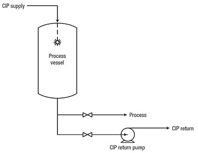
Figure 1. In this typical CIP system, CIP solution is sprayed into the tank to clean internal surfaces, and is drained or pumped through a separate CIP-return line
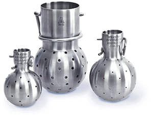
Figure 2. Typical static sprayballs, which use high flow and low pressure to clean the internal surfaces of a tank, are shown here
Spraying Systems Co.
The CIP system supplies CIP fluid to a spray device inside the vessel, which sprays the solution onto the vessel walls. A variety of spray devices are available, including static sprayballs (Figure 2) and fluid-driven orbital cleaners (Figure 3). Sprayballs are high-flow, low-pressure devices that are often used to clean smaller tanks (typically smaller than 15-ft-dia.). Fluid-driven orbital cleaners are low-flow, high-pressure devices that are typically used to clean larger tanks (greater than 15-ft dia.). Line cleaning is accomplished by circulating CIP fluid in the pipeline.
Process heel drain. A complete drain of the heel is needed to minimize waste and avoid contamination of the CIP fluid.
Initial or pre-rinse. The primary objective of the initial rinse is the mechanical removal of dirt. Water recovered from a later step in the CIP sequence is used for the pre-rinse step. Note that the pre-rinse effluent stream may contain genetically modified microorganisms, and thus will need to go through a bioinactivation process before being sent for further waste treatment.
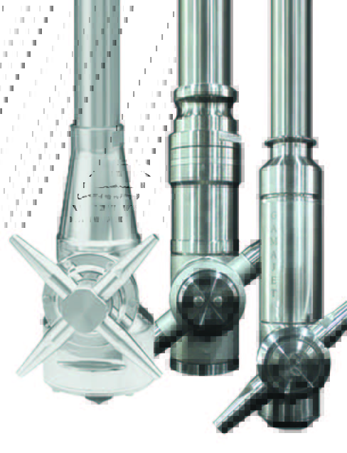
Figure 3. This photo shows three kinds of orbital, in-tank cleaners that are widely used in large-scale fermentation vessels
Gamajet
Detergent wash. This step involves chemical cleaning to remove remaining dirt. The detergent solution is circulated through the system. The solution type and concentration should be determined by plant experience. While a 2–4% caustic solution is commonly used in this step, an acid-based detergent (or both) can also be used, depending on the type of dirt or other contaminants present.
Water rinse. A once-through rinse of clean water is typically used, with no circulation, and this substantially reduces the amount of residual materials from the detergent wash step. If no acid wash is used in the CIP sequence, this water rinse step becomes the final rinse prior to either sanitization or sterilization. The rinse water should be collected for reuse as the pre-rinse fluid used in the next CIP cycle.
Acid wash. The solution used in this step may be circulated in a loop (similar to the detergent wash), and this step serves two functions. The first is to quickly neutralize and remove any remaining caustic from the detergent wash step. The second is to remove any hard-water-scale deposits that may occur within the process equipment. As mentioned earlier, depending on the nature of the dirt, an acid wash may be required to ensure dirt removal, as well.
Water rinse. This additional water rinse step is only required if an acid wash is used (to remove the bulk of any acid wash solution that remains after the acid wash step). The water from this step is collected and reused as the pre-rinse in the next CIP cycle.
CIP system configuration. There are several different CIP system configurations that can accommodate the CIP sequence described above. They vary from a single-tank system, which is based on single use of detergent solutions and rinse water, to multi-tank systems, which allow for the recovery of these fluids. Figure 4 shows a typical configuration for a multi-tank system. If an acid wash is not required, the number of tanks can be reduced to three.
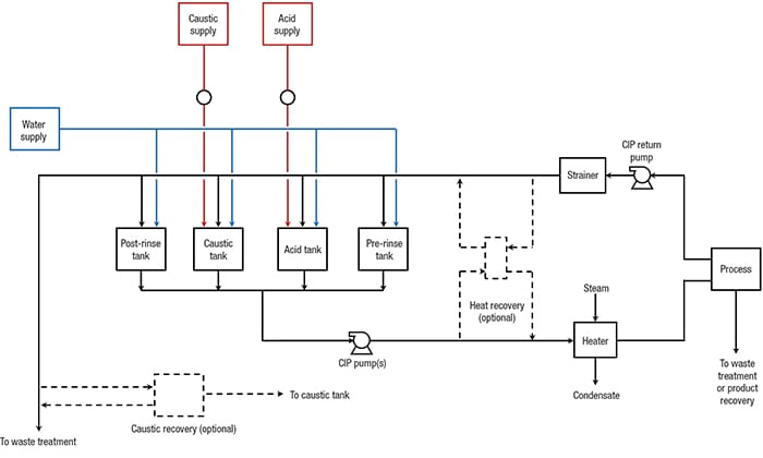
Figure 4. This block flow diagram shows the typical components of a complete CIP system
Heat-recovery and caustic-recovery modules are optional and are rarely included. Depending on the location, type and elevation of the process equipment, the facility could operate several CIP systems that are dedicated to different process areas, rather than a single system. Even if one central CIP system is possible, it may include two supply and return headers. If there is more than one GMM used in the facility, or a combination of GMM and non-GMM, then providing separate CIP systems for the different micro-organisms is advisable to prevent cross-contamination.
Equipment sizing. Process systems that are subject to CIP are divided into CIP circuits. For example, a process vessel may constitute a circuit. Piping coming out of the vessel may constitute another circuit. At times, the vessel and associated piping may be combined into one circuit. Equipment in the CIP system should be sized for the highest-possible anticipated flow and volumetric capacity requirements of the given CIP circuit. If the CIP system is designed to clean more than one circuit at a time, then the system should take into account the requirements of all the circuits that may be cleaned simultaneously. Generally, CIP systems are designed to clean one or two circuits at a time.
Tank design. Tanks are typically constructed from 304L or 316L stainless steel. Internal welds should be ground smooth and dead spots should be minimized. Internal polishing of CIP vessels is usually not required. Detergent tanks should be equipped with agitators to ease the preparation of detergent solutions. It is important to include provisions for periodic cleaning of the CIP system. This requires that the CIP tanks be equipped with sprayballs or orbital cleaners. CIP tank volumes are determined as follows: Pre-rinse tank. The volume of this tank is calculated as a function of the highest CIP flow volume, multiplied by the duration of the pre-rinse step. Typical pre-rinse times are 15–20 min for vessels, and 5 min for pipes. The pre-rinse tank usually stores the water from the final rinse. If the pre-rinse and final rinse volumetric requirements are the same — which is often the case — then the pre-rinse tank is sized to hold the final rinse volume. If the pre-rinse uses fresh water, then the size of the tank is equal to the maximum CIP flow, multiplied by the duration of the pre-rinse, minus fresh water makeup capacity. Detergent tanks. These tanks need to have sufficient volume to fill the CIP circuit with detergent solution, to enable recirculation, and to allow for losses, which will occur during switchover from water rinse to detergent wash and vice versa. Final rinse tank. The volume of this tank is equal to the highest CIP flowrate multiplied by the duration of rinse, minus fresh water makeup. This tank can be very small if the makeup rate is equal to the rinse flow requirements.
Pump design.The CIP supply pump design is an additional, complex issue. There will likely be a variety of unit operations and tanks using the same CIP solutions, but with differing flow and pressure requirements. To address this engineering challenge, variable-speed drives or parallel pumps (systems with different flows and heads) may be used to meet the range of requirements. Hydraulic losses for spray nozzles and equipment (heat exchangers, sterilizers and more) need to be calculated based on vendor information. CIP flows may be higher than the design process flows. Therefore, values for design pressure drop may not be accurate. Sprayballs usually require 20–25 psig pressure, and spray nozzles and orbital cleaners can require up to 250 psig. The pumps are normally centrifugal pumps, often with variable-speed drives. NPSH requirements are an important consideration, due to the elevated temperatures required for some CIP fluids. Low available NPSH is especially a problem in CIP return service during tank cleaning. This is because the cleaning fluid is often close to the boiling temperature and there is no static head because there is no liquid level in the tank during cleaning. One option (perhaps the best option) is to use sanitary liquid-ring, self-priming pumps, such as the one shown in Figure 5. Self-priming pumps have the ability to pump fluids with entrained gases.
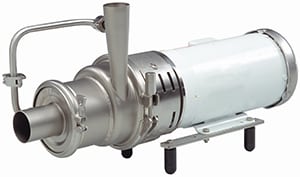
Figure 5. The liquid-ring centrifugal pump shown here is able to pump fluids with low suction head and entrained air
SPX Flow, Inc.
However, some systems have flow and capacity requirements that exceed capabilities of currently available sanitary self-priming pumps. In those cases, consideration should be given to non-sanitary self-priming pumps.
Materials of construction.The materials of construction for all process equipment and piping will need to be compatible with both the process fluids and the cleaning agents. In general, type 304/304L stainless steel will be satisfactory for wetted surfaces. However, depending upon the piping specification, type 316/316L stainless-steel material may be a less costly option, especially if stainless-steel tubing is used in smaller diameters. Elastomers and gasket material must be checked for compatibility with the cleaning agents, particularly considering the elevated temperature of the caustic wash solution. Aluminum, copper and bronze materials should not be used in the process areas, and are not acceptable in wetted portions of the CIP system.
Piping design. Key considerations of piping design for the CIP systems and the process systems being cleaned include the proper design of CIP circuits, the ability to drain CIP lines, and the appropriate segregation of the CIP system from the process being cleaned. Ideally, any dead legs should be no longer than two pipe diameters, and the overall system should be designed to drain completely. Significant biological growth can occur in water that has been allowed to stand stagnant even for short periods of time. Lines should be sized for fully turbulent flow. The general practice is to have a velocity range of 5–7 ft/s. Individual CIP circuits must be designed so that every line in a circuit maintains the appropriate velocity. Reducers in horizontal lines should be eccentric and installed with the flat side on the bottom of the pipe. All horizontal lines should be sloped to a drain point, and low points must be equipped with drains. The minimum slope of the pipe should be at least 1/16 in. per ft. Valve selection should be done with care to avoid non-drainable conditions or crevices that will not be cleaned. So-called “clean” ball valve designs are available for sizes 6 in. and less. For larger sizes, hygienic butterfly-valve designs should be considered. The tie-in point between the CIP system and the process is critical. Ideally, connections to the process should be either a block-and-bleed connection, or a line break. Specially designed, mix-proof valves are available for this service, but are limited to 6 in. or smaller in size. In some cases, flow-transfer panels may be used to restrict the connection of cleaning circuits and to provide a positive break between the process and the CIP system. The severity of potential consequences that could arise from leakage of the CIP solution into the process should guide the system designer when establishing an appropriate level of separation between CIP and process systems. 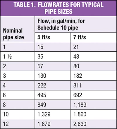
CIP flowrate.Determining the design flowrate for the CIP system requires knowledge of the number and types of systems and accessories to be cleaned. Turbulent flow conditions are required for effective pipeline CIP. This is achieved when the fluid velocity is between 5 and 7 ft/s. Table 1 shows flowrates that correspond to fluid velocity between 5 and 7 ft/s for various pipe sizes. A flowrate that produces this velocity range will be adequate for cleaning in-line equipment, as well. There are possible exceptions that should be checked. For instance, some heat exchangers and filter housings may have a larger cross-sectional flow area than the pipe feeding it. Flowrates and pressure drops should be calculated separately for this equipment. Flowrates required for equipment cleaning depend on the process, organism and type of dirt to be cleaned. Typical minimum flow values for vertical tanks and reactors range from 2 to 3 gal/min per foot of tank circumference. Additional flow and spraying devices may be required, depending on the number and locations of large nozzles, dip tubes, baffles and other internal obstructions. The choice between sprayballs and orbital cleaners is driven by vessel size and type of dirt. As vessels get larger, flow requirements for sprayballs become very large (often excessively so); thus orbital cleaners become a more economical choice. Another reason to choose a high-pressure orbital cleaner is when a high-impact force is required for effective CIP. Close coordination with spraying device vendors is required for proper device selection.
Instrumentation and controls.The extent of instrumentation in the CIP process depends on the automation philosophy in the plant. In general, recommended instrumentation includes the following:
- Visual sightglasses for CIP supply and return lines
- Temperature indicators on the caustic, acid and rinse water tanks
- Conductivity transmitters in the CIP supply and return lines
- Temperature indication and control on the CIP solution heater
- Temperature indication in the CIP return line
- Level indicators on all tanks
- Differential pressure indicators across filters and heat exchangers
- Limit switches confirming position of crucial valves
Automation.Full automation of the CIP process is recommended. The only exception to full automation would be in rare cases where flow-transfer panels are used to isolate the CIP system from the process. A variety of items in the CIP system should be automated, when possible. These include sequencing of valves for circuit lineup, minimum circulation times, permissive inputs between steps, cycle stops and alarms for CIP process values. Automation should allow for stopping, repeating or increasing the duration of steps in the CIP process.
Sterilization
In a typical biopharmaceutical process, CIP is followed by equipment sterilization. While the goal of CIP is to clean equipment surfaces (including the removal of any microorganisms found on the surfaces), the goal of sterilization is to destroy residual microorganisms (even down to trace amounts), that are still present after the CIP cycle is complete. This is particularly important in processes involving long-running mammalian cell cultures, where the presence of even one contaminating microorganism can be disastrous. The most common technique for sterilization of large-scale process equipment is moist-heat sterilization with steam. The steam-sterilization process typically involves the following three steps:
- Displacement of air with steam and heating to sterilization temperature, usually 250°F
- Holding at sterilization temperature for a minimum of 15 min (although 30 min to an hour is more common)
- Cool down, which includes introduction of sterile air to prevent a vacuum condition resulting from steam collapse as the equipment cools off
Since the pressure of 250°F saturated steam is 15 psig, this means that the equipment undergoing steam sterilization needs to be rated for a pressure higher than that. And since the usual practice is to use steam at pressure greater than 20 psig to ensure a margin of safety, this typically translates into a 25–30 psig design pressure for equipment undergoing conventional steam sterilization. This would be prohibitively expensive for the relatively low-value products that are typically produced in large-scale biofuel or biorefinery plants. As mentioned, fermentors and other vessels in such plants can range in size from 100,000 to 1,000,000 gal. This calls for a different approach to sterilization — one that would allow these vessels to be designed for a pressure of a few inches of water rather than 30 psig. This approach relies on effective CIP to keep competitive organisms at bay, and uses sterilization as backup in the event of CIP failure. Even then, conventional steam sterilization is not an option, as the design pressure and vacuum rating of the equipment is less than 1 psig. To accommodate this design pressure limitation, sterilization is done using modified steam sterilization techniques or using other sterilants instead of steam. Carrying out steam sterilization at atmospheric pressure is one way to modify steam sterilization. All the steps mentioned above would still be followed, but instead of 250°F, the vessel surfaces will only reach 212°F. This will result in a significantly longer hold period, which will have to be established based on experience. Given the design pressure of these vessels, providing adequate pressure and vacuum relief is of utmost importance, especially the latter. At this time, the only available choice for pressure and vacuum relief for these large vessels is to use pressure-vacuum-vent valves (also referred to as conservation vents) that are designed for atmospheric storage tanks. Since these are available only up to 12-in.-dia. size, depending on the size of the vessel, multiple relief valves may be required. Chemical sterilization is an alternative to steam sterilization, and this approach gets around the problem of dealing with vacuum conditions that arise during steam condensation. There are a number of chemicals that can be used as sterilants; some of the most commonly used are discussed below.
Chlorine dioxide.Chlorine dioxide (ClO2) is an oxidizing agent. In its gaseous form, it is registered as a sterilant for manufacturing and processing equipment, surfaces, tools and cleanrooms. It is a yellow to greenish-yellow gas that must be generated onsite. Chlorine dioxide generators are commercially available and they typically produce ClO2 by flowing dilute chlorine gas through sodium chlorite canisters. Chlorine dioxide can be explosive at concentrations above 10 vol.% in air, so it is important to keep its concentration safely below that. ClO2 concentrations required for sterilization are on the order of 1 mg/L. After the desired concentration is achieved, the vessel is held at this concentration for 1–2 h, the exact time to be based on experience. The last step is to remove the ClO2, which is accomplished by displacing it with sterile, filtered air. ClO2 has been used to sterilize bulk aseptic storage tanks, such as orange juice storage tanks, but to date, there are no reports of it being used in bioprocess facilities.
Peracetic acid.Peracetic acid (C2H4O3) is usually available as a mixture of acetic acid (CH3COOH) and hydrogen peroxide (H2O2) in water. It is a colorless liquid that has a pungent odor and a low pH value. Peracetic acid is produced by a reaction between hydrogen peroxide and water. It is an oxidizing biocide, which is widely used to sterilize medical, surgical and dental instruments. It is also approved for use in the direct disinfection of fruits and vegetables. But the use of peracetic acid as a hard surface disinfectant is of interest here. Commercial formulations typically contain 5–6% peracetic acid, 7–10% acetic acid, and 21–27% hydrogen peroxide, and are used in low concentrations to disperse and penetrate biofilms. They are effective against bacteria, mold, fungus and yeast. These formulations, diluted to 200 ppm in water, can be used as a sanitizing rinse at the conclusion of the CIP process. No water rinse is required after peracetic acid sanitization, and this agent will not corrode stainless steel.
Hydrogen peroxide vapor (HPV). HPV sterilization technology is used primarily in the pharmaceutical industry for bio-decontamination of isolators, freeze dryers, incubators and laboratory or production rooms. HPV is effective against a wide variety of microorganisms including fungi, bacteria and viruses. To date, there are no reports of HPV being used for sterilization or sanitization of very large-scale process systems. To make HPV work, one would have to generate HPV onsite by flash-evaporating 30–35 wt.% hydrogen peroxide. Currently, commercially available HPV generators are too small to generate sufficient quantities of HPV to carry out sterilization of very large systems in a reasonable time period. A major attraction of HPV sterilization is that there are no wastes to treat from this process, as the peroxide decomposes to oxygen and water vapor. In the foregoing discussion, we have used the terms sterilization and sanitization somewhat interchangeably. Sterilization means destruction of all organisms and that means that most or nearly all organisms are killed. However, as mentioned below, such high standards are generally not required during the production of large-scale biofuels or biochemicals. A low-cost sanitization technique that is capable of keeping biocontaminants at an acceptable level may be all that is required. Of the techniques mentioned above, one of them — sanitization with peracetic acid — is the easiest to implement via the CIP system.
Closing thoughts
The current relatively low price of petroleum has dampened some of the enthusiasm for building large-scale biofuel- and biochemical-production facilities. However, ongoing concern about climate change and sustainability will eventually lead to more of these facilities being built. Hygienic design considerations are critical to the reliable operation of these facilities, and implementation of hygienic design in a cost-effective manner will be a major factor in ensuring success of industrial-scale fermentation for the production of biobased chemicals. Edited by Suzanne Shelley
References
1. Anbarasan, P., Baer, Z, Sreekumar, S., Gross, E.,Binder, J., Clark, D., Tose, F.D., Integration of chemical catalysis with extractive fermentation to produce fuels, Nature, Vol. 491, pp. 235–239, November 2012.
2. Bremer, Phil J. and Seale, Richard Brent, “Encyclopedia of Industrial Biotechnology, Bioprocess, Bioseparation, and Cell Technology, Volumes 1-7, Clean in Place (CIP),”www.knovel.com, accessed online.
3. Rivera, Elizabeth, Equipment and Processing Report, Basic Equipment-Design Concepts to Enable Cleaning in Place: Part II, www.pharmtech.com, July 20, 2011, accessed online.
4. APV White Paper, CIP and Sanitation of the Process Plant, www.apv.com, accessed online.
5. Chisti, Yusuf, and Moo-Young, Murray, Short Review: Clean-in-place systems for industrial bioreactors: design, validation and operation, Journal of Industrial Microbiology, 13, pp. 201–207, 1994.
6. National Institutes of Health, NIH Guidelines for Research Involving Recombinant or Synthetic Nucleic Acid Molecules, http://osp.od.nih.gov/sites/default/files/NIH_Guidelines.html.
7. U.S. Environmental Protection Agency, Microbial Products of Biotechnology Summary of Regulations under the Toxic Substances Control Act, http://www.epa.gov/biotech_rule/pubs/fs-001.htm.
Author
 Bill Miley is a senior process engineer in industrial and advanced technology for CH2M (400 E-Business Way, Suite 400, Cincinnati, OH 45241; Phone: 513-587-7141; Email: bill.miley@ch2m.com). He has over 30 years of experience in all aspects of process engineering, from feasibility through post-startup, including extensive experience in pharmaceutical and chemical manufacturing, with particular skill in liquid mixing and fermentation. Miley’s specific expertise includes process and project engineering with a focus on plant process startups and training. He has two B.S. degrees (biochemistry and chemical engineering) from Michigan State University.
 Yasha Zelmanovich is manager of process engineering at EI Associates (8 Ridgedale Avenue, Cedar Knolls, NJ 07927; Phone: 973-775-7777, ext. 199; Email: yasha_zelmanovich@ eiassociates.com). He has more than 30 years of experience in the chemical, pharmaceutical and food processing industries, including all phases of process design, as well as preliminary technical and economic feasibility studies, safety and loss prevention studies, preparation of process flow diagrams, P&IDs, material and energy balances, equipment selection and more. As an adjunct professor at Stevens Inst. of Technology, he teaches a course in chemical technologies for API production. Most recently, his experience has included biorefining and biofuels projects with particular emphasis on fermentation design and application of hygienic design principles on a large scale. Zelmanovich holds a B.E.Ch.E. from the City College of New York, and an M.S.Ch.E. from the New York University Polytechnic School of Engineering.
 Jim Riley is a technology professional in oil, gas and chemicals for CH2M (1500 International Drive, Spartanburg, SC, 29303-6745; Phone: (678) 530-4554; Email: Jim.Riley@ch2m.com). He has more than 30 years of professional experience in a broad range of process and project engineering areas, specializing in batch and continuous specialty chemicals, polysilicon processes, biorefining, gasification, simple-cycle combustion turbines, and edible vegetable oil extraction and refining. Riley’s experience includes the design and optimization of complex CIP systems, process development, equipment specification, plant startup and troubleshooting, material and energy balances, P&ID development and technology transfer. Riley holds a B.S.Ch.E. from the University of Cincinnati.