Accurate interface level measurement is crucial to optimizing separation processes. Today’s guided wave radar technologies make it possible to measure thin liquid layers with greater accuracy than ever
A bottle of salad dressing can illustrate a challenging level measurement application. Like the situation with oil and vinegar separation, engineers may be called to determine the individual volumes of multiple immiscible products in a single vessel. Measuring the interface level in tanks or vessels is a common and vital objective across many process industry applications where immiscible products, like salad dressing, form distinct layers. Examples include oil over water, or low-dielectric organic solvents over acid.
Some liquids do not mix due to different molecular polarity or differences in specific gravity. When stored together, they separate into defined layers due to gravity. Accurately measuring the interface level between such products can be challenging, and if inaccurate, can lead to cross contamination, which can prove extremely costly. Newer technologies provide solutions.
Measuring interfaces
Guided wave radar (GWR) is effective and widely applied for interface level measurement (Figure 1), but it requires the top product layer to be of a certain minimum thickness to be measurable. Advanced technology in the latest generation of GWR devices can cut that minimum thickness in half or even less, helping users increase the efficiency of their operations and reduce costs.
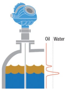
Figure 1. Guided-wave-radar level instruments are an effective solution for multi-product interface measurement in tanks
The need to measure interface level arises when it is necessary to know the volume of the upper product layer, which can be determined from its thickness and vessel diameter. This could include situations when a user wants to drain off only the top fluid and requires an indication of when to stop. Interface measurement is also essential for efficient separation processes, where it is critical to control the flow of both fluids out of the vessel into independent channels with minimal cross contamination.
In most cases, the two liquids separate naturally because of their differing densities, with the lower-density liquid settling on top of the higher. For example, when oil and water occupy the same vessel, oil floats on top of water. The interface point to be measured in this example would be the upper level of the water and the lower level of the oil.
In an oil production process, a separator upset combined with a lack of visibility into the interface location can result in oil being sent to the water tank or water being sent to the oil tank, both of which are undesirable. Oil sent out with water gives away product and could result in environmental fines. Unrecovered oil in the water tank from a multiple well pad facility could siphon off more than $1 million a year of revenue, while excess water in the oil tank could cause an unexpected capacity loss, resulting in a spill or well shut-in from a high-level alarm.
The accuracy of interface measurement depends on the specific process conditions, such as the difference between dielectric constants of the products, and the presence of a distinct interface. Sometimes the fluids do not separate entirely, and instead form an emulsion or “rag layer” (a mix of the two products) between them. Typically, the thicker the emulsion layer, the more challenging it becomes to accurately measure the interface level.
Technology selection
The most basic way to measure an interface level is via a sight glass on the side of a tank. However, this method has some obvious disadvantages. First, it must be read manually, which is both time-consuming and labor-intensive, as it requires operator inspection. Second, a sight glass will not always give a clear indication unless there are multiple connections to the vessel to allow the interface in the glass to match what is in the vessel. Third, sight glasses need regular cleaning, and in applications where condensation can occur, this can prevent the operator making an accurate measurement.
Other level measuring alternatives capable of identifying an interface layer, at least to some extent, include floats and displacers, capacitance transmitters, ultrasonic transmitters, differential pressure meters and magnetostrictive sensors. However, these technologies have various limitations in terms of their resolution, accuracy, and reliability in challenging process conditions, plus maintenance requirements.
The many advantages provided by GWR in comparison has seen it become one of the most widely applied solutions in interface applications. GWR provides accurate and reliable measurements in vessels with tight geometry, in chambers, and in tanks of all sizes. No compensation is necessary for changes in the density, dielectric properties, or conductivity of the fluid. Moreover, changes in pressure, temperature, and most vapor-space conditions have no impact on its measurement accuracy. GWR instruments need minimal maintenance because they have no moving parts, and they can easily be installed as a replacement for older technologies, even while there is liquid in the tank.
In a GWR installation, the instrument’s transmitter is usually top-mounted (Figure 2), with the probe extending to the full depth of the vessel. A low-energy pulse of microwaves, travelling at the speed of light, is guided down the probe. At the point of the liquid level, a significant proportion of the microwave energy is reflected up the probe to the transmitter when the pulse encounters the sudden change in dielectric constant when passing from air to liquid. The transmitter measures the time delay between the transmitted and received echo signal. An onboard microprocessor then calculates the distance to the liquid surface.
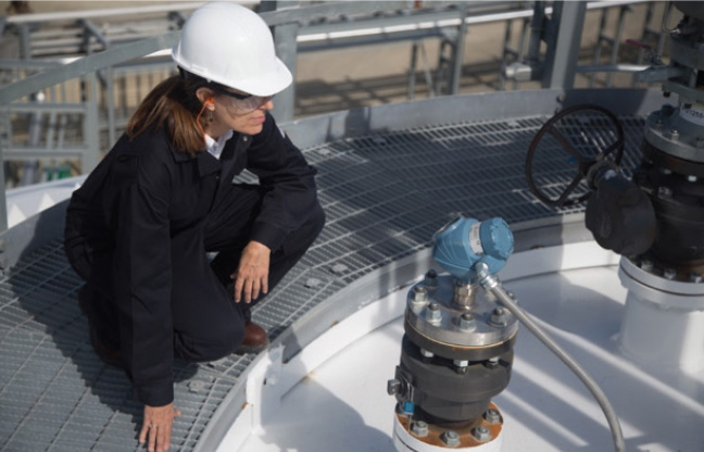
Figure 2. GWR level instruments are normally mounted on a tank roof through a flanged spud
A portion of the pulse will continue down the probe through the top layer of liquid, and when it encounters the change in dielectric constant at the interface point, a second echo can be detected from the top of the second liquid at a point below the initial liquid level.
This works as described provided the liquid on top has a lower dielectric constant than the lower liquid, which is the case with oil on water since most oil products have a very low dielectric constant, <5 typically, and water is >50.
In the rare cases where the product lying on top has a higher dielectric than the one below, top-down measurement using GWR will be ineffective. In this circumstance the mounting position can be inverted so the instrument is installed on the tank bottom, but this will only be able to determine the interface position and not the top level.
Thin-layer measurement
The reason why the upper product must be of a certain minimum thickness when using GWR in interface applications is to enable the instrument to separate and distinguish the echoes of the two liquids (Figure 3).
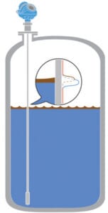
Figure 3. New software makes it possible for the instrument’s transmitter to differentiate between two pulse echoes, even when they are very close together. This allows for accurate measurement of thin layers
For most GWR instruments available today, the minimum thickness must be between 6 and 8 in. (125 and 200 mm) depending on the transmitter model and probe style being used. However, some instruments provide functionality that enables the minimum detectable thickness of the upper product layer to be cut in half, to 2.5 in. (60 mm). This improvement is possible because of new software algorithms that allow the transmitter to detect closely spaced signal peaks without having to decrease its signal bandwidth. Maintaining signal bandwidth allows the instrument to retain its high sensitivity and ability to handle disturbances. This helps operators improve insight into separation processes, therefore improving process optimization and reducing production losses.
The ability to detect a thinner upper-product layer is especially beneficial in cases where no second product should be present in the vessel. For example, detecting a hydrocarbon on top of methanol is an indication that there is something seriously wrong with the process. It can also be very beneficial in separators and scrapers, where the operation of a vessel can be optimized by reducing safety margins.
The tools available for oil producers and chemical manufacturers working with immiscible products are improving, allowing plants to optimize processes, resulting in increased operating efficiency and profitability. The ability to determine the contents of a tank, with thick or thin layers, can improve process control and possibly identify when something has gone wrong, allowing for timely corrective action.
Edited by Dorothy Lozowski
Reference
1. Rosemount 5300 Level Transmitter— Guided Wave Radar, www.emerson.com/en-us/catalog/rosemount-5300-gwr-transmitter
Author
 Denny Nelson is a solutions engineer for Emerson’s Automation Solutions business in Göteborg, Sweden (Email: denny.nelson@emerson.com; Phone: 0046 313 370279; LinkedIn: www.linkedin.com/in/denny-nelson/). Nelson joined Emerson in 2017, and he holds a B.Sc. degree in product design engineering from The University of Skövde and an MSc engineering management degree from Jönköping International Business School.