Testing and characterization techniques are rising to meet the demands of increasingly complex materials and applications
Ensuring the integrity of materials is essential in the chemical process industries (CPI) for the continued maintenance of long-lifetime process equipment like vessels and pipelines, usually via nondestructive testing (NDT) techniques such as ultrasonic, eddy-current, radiographic or guided-wave testing. Many companies also must employ materials testing and characterization techniques for quality assurance of the products they are selling. Both facets of materials analysis — whether inspecting equipment used in processes or the products of the processes themselves — demand that companies stay up-to-date with the most modern methods for materials testing and characterization.
Sizable recent investments in dedicated materials-testing facilities by major companies underline the significance of these efforts. Furthermore, accelerated developments in applications for complex materials, such as composites and nanomaterials, have necessitated the adoption of more advanced testing and characterization methods.
Testing product quality
In September, Royal DSM (Heerlen, the Netherlands; www.dsm.com) announced a $5-million investment to open a dedicated research and technology center (Figure 1) for its DSM Engineering Plastics division in Troy, Mich. “The focus that DSM is placing on advanced testing methods comes from an eagerness to validate the performance of its products under application-relevant conditions,” says Juliana Bernalostos-Boy, manager of application and product testing at DSM Engineering Plastics. According to William Senge, director, research and technology, Americas for DSM Engineering Plastics, by emphasizing application-specific experiments and close collaboration with customers, the site will “bridge the gap between intrinsic materials characterization and application testing.” These tasks will include fluid aging of plastics, as well as simulations of key secondary operations the plastics may encounter at customers’ sites, says Senge. In order to most accurately test engineering plastics for their behavior in end-use applications, the materials will be exposed to application-relevant conditions prior to testing via a variety of conditioning options, including ovens, environmental chambers and chemical-resistance setups. “The environmental chambers will allow us to condition parts and materials to 95% relative humidity at 95°C. This is an extremely aggressive conditioning that we see becoming more and more relevant in future applications,” explains Bernalostos-Boy.
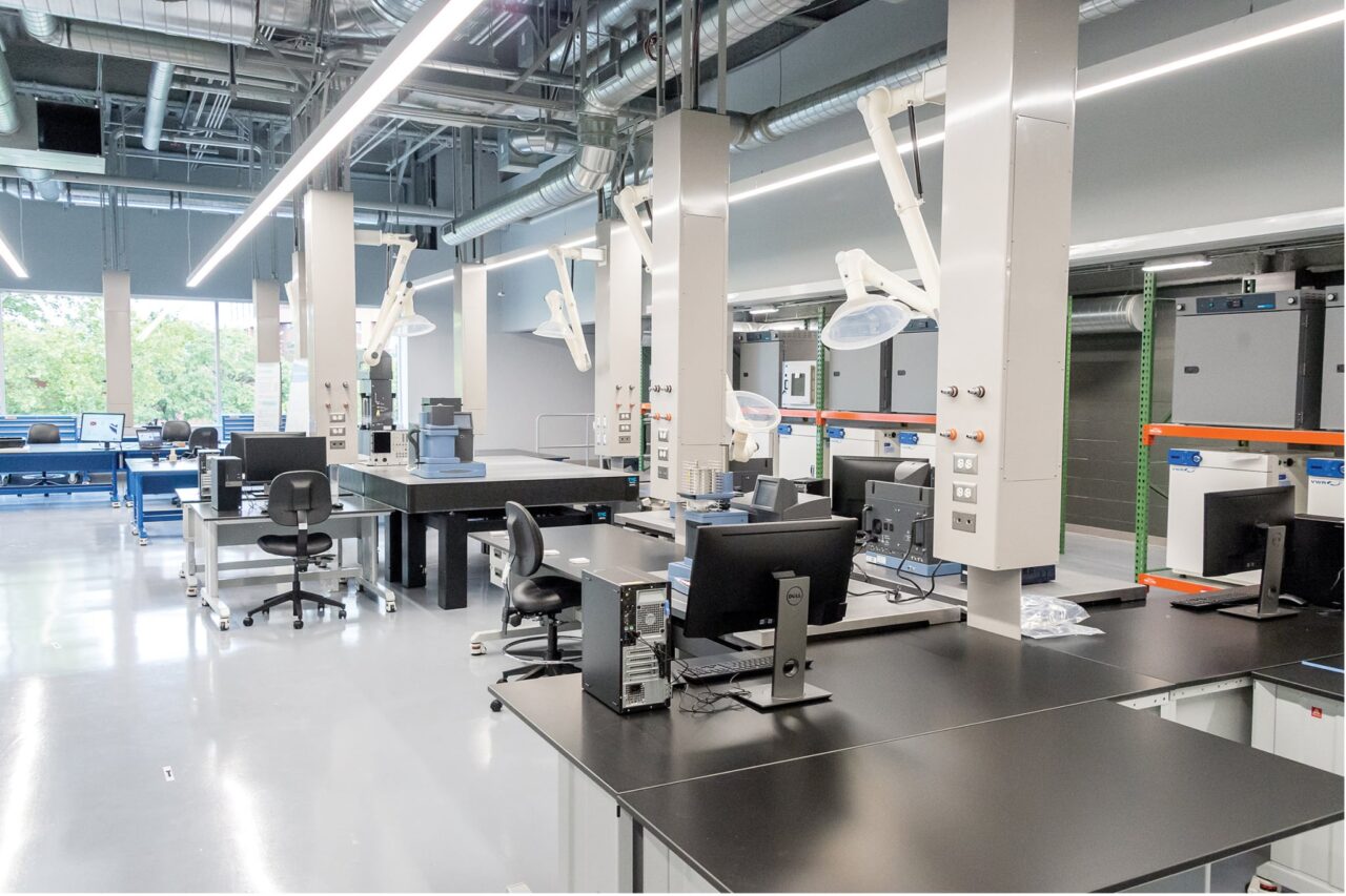
FIGURE 1. DSM’s dedicated materials-testing facility will condition engineering plastics in order to evaluate their performance in a variety of processing and end-use applications DSM
When testing nanomaterials and their end products, special conditions must be considered. A collaboration between Oxford Instruments plc (Abingdon, U.K.; www.oxford-instruments.com), National Physical Laboratory (NPL; Teddington, U.K.; www.npl.co.uk) and the National Graphene Institute (NGI, Manchester, U.K.; www.graphene.manchester.ac.uk) is seeking to develop a turnkey commercial metrology system for graphene characterization and various other nanotechnology applications, such as high-end instrumentation. Such a system would not only decrease costs and complexity, but would establish the industry’s first-ever set of primary resistance standards, allowing for extremely precise resistance calibrations and other measurements during the production of instrumentation devices and other electronics. By taking advantage of graphene’s manifestation of the quantum Hall effect, a phenomenon used to determine electrical resistance using low temperatures and strong magnetic fields, the group will harness this behavior to accelerate the commercial adoption of graphene by enabling commercially applicable nanoscale materials characterization.
Improved statistical analysis
For obtaining useful information from materials characterization, the method of analyzing the results can be as important as the characterization method itself. A research team from North Carolina State University (NCSU; Raleigh; www.ncsu.edu), the National Institute of Standards and Technology (Gaithersburg, Md.; www.nist.gov) and Oak Ridge National Laboratory (Oak Ridge, Tenn.; www.ornl.gov) has found a new analysis method that yields even more useful characterization results from diffraction and spectroscopy data (Figure 2). “Currently, the dominant method of analyzing diffraction patterns involves modeling the material as a single unit cell. The parameters in this model are refined using a ‘least squares’ approach, which leads to single estimates of each structural parameter,” says Jacob Jones, NCSU professor of materials science and engineering. However, explains Jones, since materials are naturally heterogeneous, this method results in an oversimplified representation of the actual material structure.
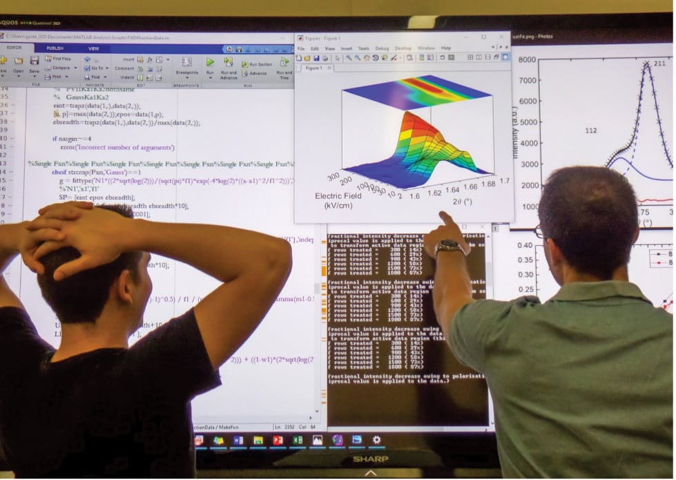
FIGURE 2. Analyzing materials-characterization data at the atomic level using probabilistic terms yields more useful results North Carolina State University
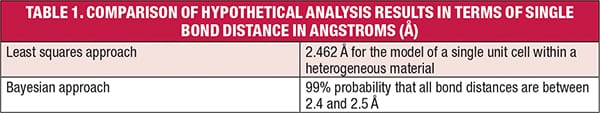
The new characterization approach, based on Bayesian statistics, allows for materials’ structural features to be described in terms of probability distributions, rather than a single value assumed for a model of a single unit cell. Table 1 illustrates how results from least squares and Bayesian statistical analysis could differ, in terms of a hypothetical measurement of a single bond distance. “Using probability distributions instead of single-valued solutions provides a better ability to predict or calculate how these materials will perform in applications, and a better way of qualifying manufactured materials,” says Jones.
The team believes that the ability to assess materials’ structure in probabilistic terms will prove to be extremely valuable for quality assurance and process monitoring for products such as metals, ceramics and powders. “A useful analogue would be to consider the manufacture of particles — a customer should want to know the size distribution of the supplied particles, not simply an average or most-likely size,” describes Jones.
Although the Bayesian analysis approach is based on ubiquitous characterization techniques like diffraction and spectroscopy, making it powerful and applicable across various industries, Jones says that widespread adoption is not without challenges. “One immediate challenge to adoption is the development of software that can readily incorporate this method in evaluating diffraction and spectroscopy data. Codes can readily be written by a specialist, but we need to make them widely available to industry.”
The method is particularly useful for materials whose structures are difficult to characterize using a single type of experiment and require consideration of multiple characterization methods, such as metal oxides. The Bayesian method allows users to integrate data sets from different experiments to obtain better certainty. The team also cites the method as being well-suited for analyzing composite materials consisting of dissimilar material structures.
A toolkit for composite inspection
There is no doubt that the nature of the material being tested can impact the effectiveness and application of certain testing techniques. Composite materials, due to their complex internal structures, possess many properties that make them suitable for heavy-duty applications in aerospace, renewable energy and many other industries. These applications demand reliable longterm performance, so ensuring materials’ integrity is key.
Researchers at Sandia National Laboratories (Albuquerque, N.M.; www.sandia.gov) are investigating NDT methods for composites. “The techniques that we’ve focused on are currently being deployed in a laboratory setting. We use a range of handheld devices that can be taken into the field as well as scanning platforms that are designed to collect a tremendous amount of data very quickly,” says David Moore of Sandia National Laboratories. Two techniques being investigated are infrared imaging, and ultrasonic scanning devices, such as hand-contact roller probes. Both methods can cover a wide range of sample sizes. Moore emphasizes that each testing method brings with it unique capabilities and limitations, and when used together will create a comprehensive toolbox for inspecting composites. “Each method tells a little portion of the story. Ultrasonics can measure material thickness; infrared technologies can measure surface temperatures, so both techniques coupled together give a better idea of what is happening with a material during its service life.”
According to Moore, a composite’s porosity is one of the primary parameters that must be known. Moore’s research is focused on the group of composites known as prepregs, where the resin is “impregnated” within the carbon material.
Here, a sample is laid out in plies and stacked for the desired thickness. Air is rolled out of the ply stack before being placed in an autoclave for the curing cycle. Temperature is applied to the parts, and pressure and time are two additional parameters that can be varied. As temperature increases, the resin viscosity decreases until glass transition is reached. At this point, the void pressure is high. To eliminate void formations, the desired autoclave pressure must be applied at minimum viscosity. If pressure is applied prior to minimum viscosity, voids will be trapped inside the resin and porosity will be created within the component. “This means that the ply layers are not bonded cohesively and the porosity creates a stress initiation site for potential material failure,” explains Moore. Porosity variances, as well as density changes, can be detected by measuring the acoustic wave as it travels through a sample. Air bubbles scatter sound, so the porosity can be evaluated by measuring the attenuation change through the material thickness.
Another important feature within composites is the alignment of the fibers, or tow. In many applications, misalignments can indicate causes for concern, so their presence and severity should be assessed. Also, the transition from thicker to thinner areas within a composite can create a large stress concentration. “These transitions are the most difficult areas to inspect,” says Moore, because researchers must know the exact locations simply from looking at a drawing. Ultrasonic and infrared rapid scanning systems denote localized thickness on screen using x-y coordinates. “If the composite has been impacted during service, we would like to understand what any of these inspections can tell us about the remaining strength of a component,” Moore says. “If you know the strength, then you can develop proactive maintenance schedules around the collected inspection data.”
Terahertz technologies
An area of emerging technology in the NDT realm is terahertz (THz) devices — those that operate in the frequency range between radio and microwaves. Much work has been done in harnessing THz radiation for materials testing and characterization purposes because of its high chemical selectivity and ability to penetrate typically opaque or translucent materials, as well as take complex measurements within multi-layer structures. THz is especially useful with non-metallic materials, such as plastic, rubber, glass, ceramic and wood. “Compared to the conventional methods used for nondestructive material testing, such as radiography or ultrasound, terahertz technology enables non-contact inline measurements using small-footprint testing equipment. Especially in high-volume productions like polymer tubes, it is essential to have direct feedback to control the production process,” explains Joachim Giesekus, head of the Terahertz Sensors and Systems Group at Fraunhofer Heinrich Hertz Institute HHI (Berlin, Germany; www.hhi.fraunhofer.de). Previously, THz technology was almost strictly limited to academic and research settings, but recent advances have made it more accessible for industrial use. “Until now, terahertz devices, in particular the sensor heads, have been expensive and bulky,” Giesekus says. Earlier this year, at Hannover Messe, Fraunhofer HHI debuted a breakthrough in THz measuring devices — a system with compact sensor heads constructed from low-cost materials (Figure 3). In typical THz measuring systems, the sensor heads’ receiver and transmitter are two distinct components that must be carefully mounted within a casing. This arrangement dictated that measurements be taken at a precise angle, making the system especially susceptible to changes in positioning due to vibration, for instance. Fraunhofer HHI’s compact sensor heads feature an integrated chip — dubbed a “transceiver” — that can simultaneously transmit and receive.
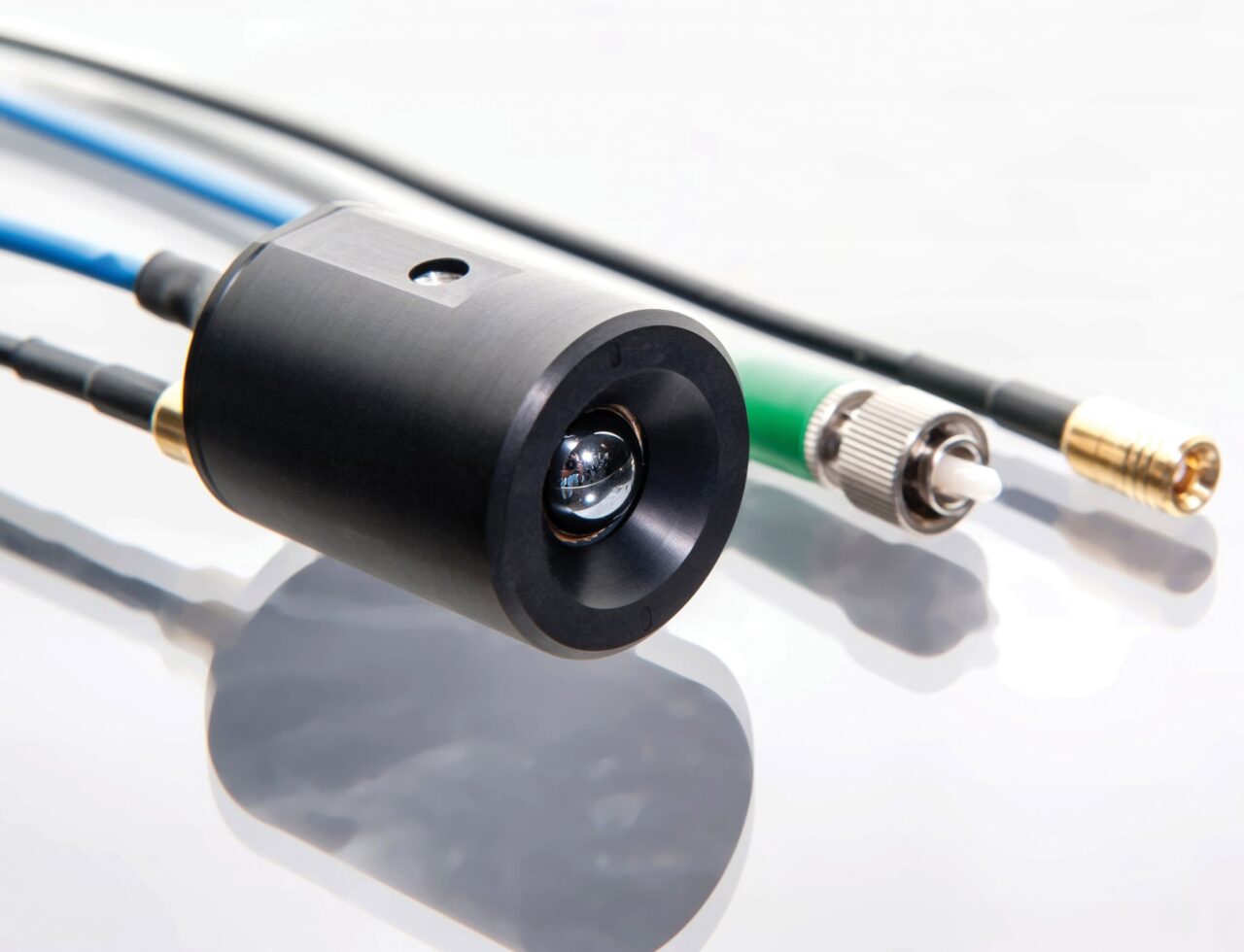
FIGURE 3. Compact sensor heads combine the transmitting and receiving functions to make THz technologies more commercially attractive Fraunhofer HHI
While these prototype sensor heads have mainly been used for inline defect detection in the production of plastic pipes, Giesekus says they are also suitable for analyzing coatings on fiber composites and inspecting defects in polymer devices. Traditional NDT devices, such as those utilizing eddy-current methods, are well-suited for use with metallic substrates, but they fail with fiber composites, which have poor conductivity. Here, THz technologies can provide many benefits, although Giesekus emphasizes that the prototype sensor heads are still 1–2 years away from widespread adoption. “The development of semiconductor materials optimized for sending and receiving THz radiation is still challenging,” he says. In addition to the sensor heads, Fraunhofer HHI is also working to develop next-generation THz spectrometers.
Another group touting the advantages of THz technologies for NDT is TeTechS (Ontario, Canada; www.tetechs.com), which has developed TeraGauge, an NDT device designed specifically for use in industrial environments, where dust, humidity and other interferences may be present. “Terahertz has long been viewed as elusive, and has only recently emerged as a real-world solution amongst major players like x-ray and infrared technologies,” says TeTechS founder and chief executive officer Daryoosh Saeedkia, citing expense as a main factor that has limited THz’s expansion beyond research applications. However, he describes several advantages of THz over traditional NDT methods. “Unlike x-rays, terahertz is non-ionizing, which ensures it is not harmful to the user. Furthermore, when compared with ultrasonic or infrared techniques, THz is less sensitive to sample position and environmental factors, such as vibration, temperature and humidity.” TeraGauge employs a “time-of-flight” principle (Figure 4), which uses the speed of light in the material under test to extract parameters such as thickness or density. TeTechS has recently employed TeraGauge technology inside IMDvista Layer industrial measurement systems, aiding in the inspection of the thickness of multilayer plastic containers and thin-wall packaging. TeraGauge is also applicable for void detection and multilayer thickness inspection of hoses, tubes, paints and coatings. In addition to TeraGauge, the company is also developing handheld THz devices and a THz-powered fiber-coupled gage for rapid inline measurements.
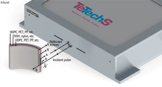
FIGURE 4. A time-of-flight approach allows THz-based inspection of multilayer plastic parts TeTechS
As the CPI continue to demand more complex materials for increasingly challenging applications, materials testing, characterization and inspection will certainly be an essential factor for ensuring ongoing operational success. ■
Mary Page Bailey