A customized inspection and maintenance program will minimize operational and performance problems with glass-lined equipment
Glass-lined steel equipment is used in a wide range of chemical processes that involve harsh chemicals, including the production of pharmaceuticals, specialty chemicals, agricultural products and polymers. One of the reasons for the attraction is that glass is resistant to attack from most chemicals and to mixtures of corrosive materials. In addition, it has a smooth, anti-stick surface, is easy to clean, and does not introduce impurities to the process materials.
The metals that compete with glass for corrosion resistance are tantalum, titanium and zirconium, all of which are several times more expensive than glass-lined steel (Figure 1). Glass-lined steel can be used with most acid or alkaline media, since glass withstands attack from most substances in both oxidizing and reducing environments. The exceptions include fluorides at any temperature or concentration; hot, concentrated phosphoric acid; and highly alkaline chemicals at elevated temperatures.
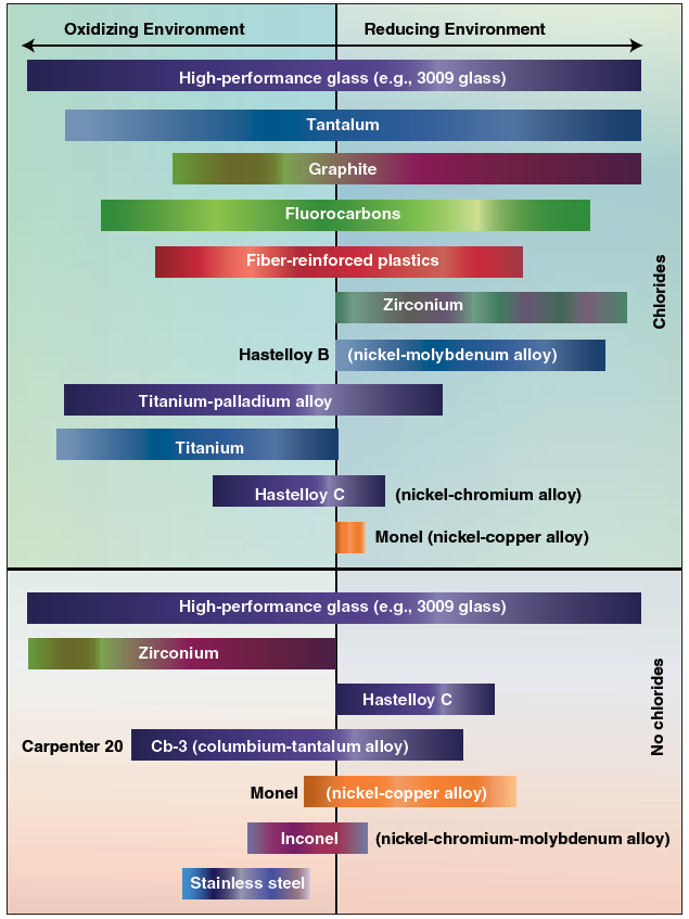
FIGURE 1. The corrosion resistance of glass is compared with that of other metals and alloys in reducing and oxidizing environments, in the presence and absence of chlorides
Glass-lined vessels typically consist of a carbon-steel body with a bonded inner lining of specially formulated glass (Figure 2). The glass is composed of several oxides and silicates. It is blended and heated to the melting point, emptied through a chute, quickly cooled and solidified into particles called frit. The first coat of glass applied to the steel is the ground coat (the middle layer in Figure 2); it has limited corrosion resistance and is used solely to develop a chemical bond with the base metal (the bottom layer in Figure 2). After the ground coat is cooled, the chemically resistant glass (the top layer in Figure 2) is applied. This procedure is repeated until a desired glass thickness is achieved, which is usually 40–90 mils.
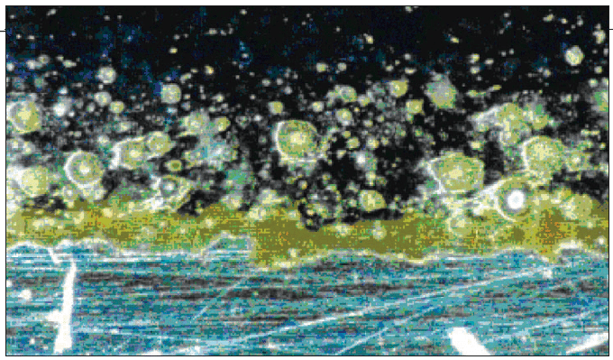
FIGURE 2. A glass-lined vessel has a carbon-steel substrate (bottom layer) bonded to an inner lining of base glass (middle layer). High-performance glass (top layer) is coated onto the base glass to the desired thickness
Equipment that is often supplied with a glass lining includes reactors, storage tanks, columns, dryers and filters, as well as pipes, valves and fittings. The internal components of the vessels, such as agitators, baffles and dip pipes, are also supplied with glass coatings. In general, glass-lined vessels are designed to operate at temperatures up to 500°F (260°C) and pressures of 130–150 psig (9.14–10.55 kg/cm2), although they can be built to withstand much higher pressures.
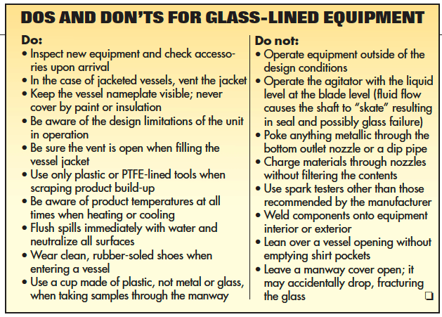
The leading cause of problems in the operation of glass-lined equipment is mechanical damage resulting from impact, and the second is thermal shock, caused by heating or cooling a vessel too quickly. These and other problems can be avoided or minimized by proper operation of the equipment and by educating personnel in the procedures for working with glass-lined equipment (see box below).
Preventive maintenance
The key to a long, healthy life for glass-lined equipment is an inspection and maintenance program that is designed for early detection of damage. A small chip or pinhole, if not repaired immediately, can lead to corrosion of the steel substrate and could result in major harm to the equipment. The inspection process starts with a thorough review upon delivery of the glass-lined equipment to the plant to ensure it was not damaged in transit. Thereafter, the equipment should be inspected at regular maintenance intervals ranging from several times a year, to once every two years, depending on the severity of service. More-frequent or even continuous testing may be conducted if the operating conditions are especially severe, or if damage is suspected.
A typical maintenance checklist for glass-lined equipment should nclude: visual inspection of the lining; spark testing for signs of glass-lining failure; glass-thickness readings; inspection of tantalum repair plugs and patches, if installed; vessel nozzle connections; and vessel jacket connections. As in conventional equipment, the list should also include motor and drive performance and the mechanical seal and lubricator (if applicable).
Spark testing. Glass linings should be electrically tested after installation and at regular maintenance intervals in order to detect small defects before they become more serious problems. A spark test can be performed with either d.c. or a.c. spark testers, which apply approximately 6,000 V at very low amperage. In either case, the spark tester consists of a hand-held brush that is connected via a cable to a portable detector. The inspector carefully brushes the glass surface, using a semi-circular motion, until the entire surface has been covered. If the brush encounters so much as a pinhole, current flows to the steel shell and arcing occurs.
Incidentally, d.c. spark testers are the preferred way to check vessel linings because they are grounded to the steel structure. The a.c. types, which are connected to a power outlet, are generally used for checking components that are completely encapsulated in glass, such as agitator blades, where grounding is not possible.
Also available are permanent d.c. systems that are installed in a vessel and monitor the integrity of the glass lining continuously while the vessel is in service. A conductive glass electrode is mounted on an internal accessory, such as a flush valve at the bottom of the vessel, and the other end of the circuit is connected to the outside of the grounded steel shell. If there is a leak in the glass, a current of a few milliamps flows between the electrodes via the conductive liquid contents of the vessel and activates audible and visual alarms. Besides continuous monitoring, an online system avoids the need for someone to enter the vessel to conduct an inspection.
Another option is to use a portable instrument that is based on the same principle. In this case, the vessel is filled with a conductive liquid, and a probe is suspended in the liquid on a cable. Although monitoring is not continuous, the test can be done as often as considered necessary, and the probe can be used in multiple vessels. With either system, the approximate location of a leak can be determined by filling or draining a vessel until the alarm is activated or deactivated.
Monitoring glass thickness. Another inspection task that is done electrically is measurement of the glass thickness, a calculation that is critical to the life of a vessel. It is performed with a handheld magnetic induction or eddy-current type instrument that comprises a probe on a cable. When the probe is touched to the surface of the glass, it sends out a current that is reflected from the steel backing of the vessel. The time taken to receive the feedback signal indicates the glass thickness with an accuracy of at least ±5%. This value is displayed on the instrument. To conduct these tests, the vessel should be mapped in a grid pattern, with readings taken at intervals of 24–36 in. (61–91.5 cm).
The appropriate interval between glass-thickness measurements depends on a number of factors. If the reactants used in a process are very aggressive, it may be wise to measure the thickness of the reactor’s glass lining every three to six months. The frequency of inspections should increase as the vessel ages. Areas that exhibit a loss of fire polish (the smooth finish achieved in the glass furnace) should be more thoroughly inspected and monitored. In particular, agitator blades and baffles are more likely to show signs of wear and should be tested more frequently than other areas.
It is good practice to maintain a logbook for each vessel, indicating the date of installation and the dates and results of spark tests, visual inspections and glass-thickness tests. The log will help maintenance personnel to determine the estimated service life of the equipment and could help prevent a vessel failure. It is advisable to call the equipment manufacturer when the thickness of the glass lining thins to about 0.03 in. (0.08 cm), as it is probably time to take the vessel back to the factory for reglassing. A reglassed vessel can carry the same glass -lining warranty as a new vessel.
Before sending a vessel to the manufacturer for repair and reglassing, it is necessary to clean the vessel and jacket thoroughly, removing all chemicals and heat-transfer fluids. Insulation should also be removed, as well as all accessories not subject to repair or replacement. These may include the agitation system, clamps, split flanges, pipes, valves and fittings. Any plugs or patches should also be removed, as product may have become trapped behind them.
Field repairs
Reglassing, however, is the remedy of last resort and should not be necessary until the lining has been worn thin by years of service or has been severely damaged. Such areas can be repaired economically by means of a plug or patch made of tantalum, which is used because of its corrosion resistance. Plugs are designed to repair small holes, up to 4 in. (10 cm) dia., whereas patches are intended for larger areas of damage. Old repair plugs and patches should be checked during an inspection. Loose plugs and patches should be replaced, not retightened.
A tantalum repair plug consists of a stud, nut, disc and a gasket of polytetrafluoroethylene (PTFE, or Teflon) (Figure 3). It can be used to repair defects by the following procedure:
• Clean the area to be repaired
• Remove the damaged glass
• Choose the appropriate size plug
• Drill and tap to the appropriate dimensions
• Screw in the stud; ensure that the hole is perpendicular after the plug is installed; ensure that the gasket is sealed properly
• Apply a cement into the cavity
• Install the PTFE gasket
• Install the disc
• Screw on the nut
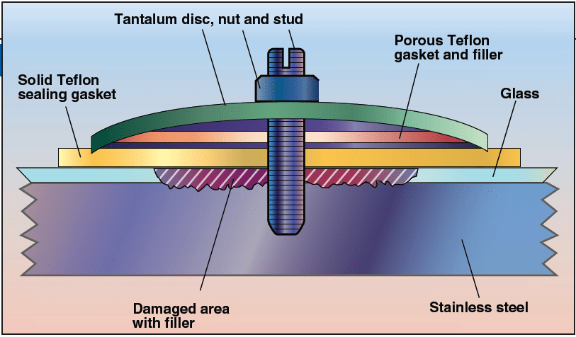
FIGURE 3. Damaged areas of glass can be repaired with a tantalum plug, or a patch comprising a sheet of tantalum with a PTFE gasket. The patch is placed across the damaged area and is fastened into place with tantalum studs and nuts around its periphery
Upon drilling a hole, prevent the tip of the drill from slipping over the glass by turning the chuck by hand and applying pressure, such that the tip cuts its way through the lining.
Be sure to mill at slow speed and in short bursts to avoid chipping the glass around the periphery of the hole. Complete the drilling process by using a ball mill or conical mill. Prior to installing the patch, a filler, such as furan or silicate, is injected into the damaged area (Figure 4). In the case of larger holes (larger than 4 in. dia.), a sheet of tantalum, with a PTFE gasket, is placed across the damaged area and is fastened into place using tantalum studs and nuts around its periphery.
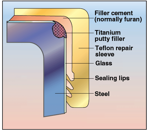
FIGURE 4. Nozzle repair for small holes, up to 4 in. (10 cm) dia. is performed with filler and a gasket of polytetrafluoroethylene (PTFE, or Teflon)
This repair system can also be employed to restore damaged glass around a nozzle, which is glassed on its interior and on the nozzle face. If the steel has been damaged, the affected area may be filled with titanium putty or furan, and a tantalum sleeve may be installed inside the nozzle. A solution that is less expensive than tantalum for repairing glass around nozzles is the use of a repair sleeve made of PTFE. In this approach, titanium putty may be used to fill the damaged area. Then, a layer of cement is added, and the PTFE sleeve is installed on top of the cement to form a seal.
Causes of glass failure
There are many reasons for glass failure in glass-lined steel equipment. Most may be avoided by following the correct procedures when working with the equipment. For example, mechanical shock, which accounts for approximately 75% of all failures, is often the result of human error.
Mechanical shock and chemical attack. A common cause of glass failure from mechanical shock is objects falling on or against the outside or inside of a vessel. A sharp blow on the outside can cause the glass to “pop off,” depending on the severity of the blow. If mechanical shock is suspected, the vessel must be inspected immediately and, if necessary, repaired before further use. An impact directly on the glass will result in crushed glass at the impact point, with chunks of glass fracturing off around the area (Figure 5).
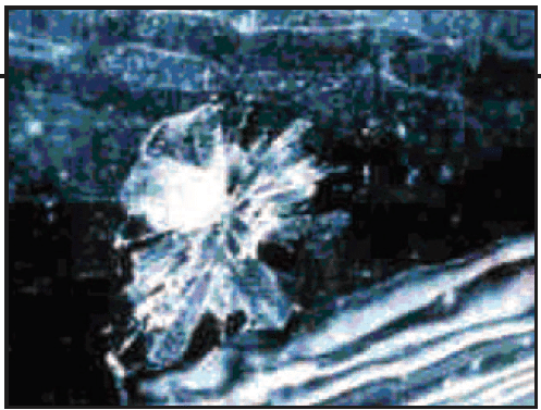
FIGURE 5. Approximately 75% of all failures in glass-lined steel equipment are caused by mechanical shock resulting from impact on the outside
of the steel substrate
Entry into a vessel for inspection or maintenance always creates a potential for mechanical damage. In addition to taking normal safety precautions, a mechanic must wear a new or dedicated pair of rubber-soled shoes to prevent scratching the glass lining, and empty clothing pockets before entering the vessel. Items such as metal belt buckles or studs in clothes should be removed to prevent accidental scratching of the glass in the manway nozzle. Any tools that are needed can be lowered down in a sturdy cloth or canvas bag once the mechanic is safely inside the vessel.
Avoid scratching or tearing the surface of a vessel’s glass lining when removing residual reaction products. Plastic or wood scrapers — never metal tools — can be employed, but high-pressure water-jet cleaning is preferred. Whenever a glass-lined vessel is lifted and moved, it is important to follow the manufacturer’s recommended procedures for handling and rigging. The lifting lugs on the equipment are designed to carry the weight of the vessel and should be used as instructed for lifting and setting the vessel in place. Shortcuts, such as using nozzles as lifting lugs, can subject the glass lining to excessive stress and possible damage.
It must also be understood that glass is not completely inert and is always undergoing local chemical reactions at the surface. What allows glass-lined steel to be used with most corrosive materials is the slow rate of reaction. Acids, alkalis and even water can corrode glass; the attack rate is determined by temperature, duration, and the concentration of reagents.
A reactor’s glass lining may be eroded by abrasive solids in the reactants. Abrasion is characterized by a loss of fire polish and, in severe cases, a rough, sandpaper-like finish. Abrasion combined with acid corrosion can result in severe glass-lining failure, as abrasion weakens the silica structure, which accelerates the rate of acid corrosion.
Thermal shock. Glass-lined vessels are made by bonding a layer of glass to steel, as noted earlier. Since steel and glass have different coefficients of thermal expansion, glass-lining failure can result from abrupt changes in the temperature of the glass, causing small, but thick, pieces of glass to fracture off the steel substrate. In most cases, the steel will be exposed. Unlike failure from mechanical shock, thermal shock usually damages the glass lining in large areas (Figure 6). Consequently, repairs with tantalum plugs or patches are often not practical and the vessel must be completely reglassed.
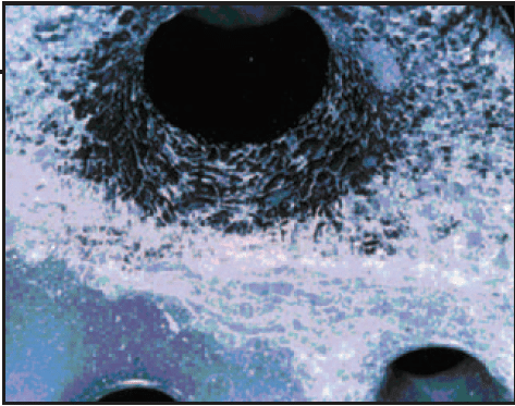
FIGURE 6. Thermal shock is induced
by an abrupt temperature change. This change places the glass in tension because it eliminates the glass’ compressive stress
The basis for thermal shock is as follows:
The glass lining is sprayed on the prepared steel, and then moved into the furnace to “fuse” the glass and steel together, via mechanical and chemical adherence. Glass is fused onto steel at approximately 1,600°F (870°C), at which temperature the steel is comparatively ductile and the glass is an amorphous, viscous mass. The glass solidifies at around 600°F (320°C). This is the null point — a temperature at which the glass is under neither compression nor tension. When the glass lining cools to ambient temperature, it is under a residual compressive stress, which greatly strengthens the glass and makes it resistant to thermal and mechanical shock. However, excessive compression in glass increases the tendency of convex glass surfaces, such as outside radii or vessel nozzles, to spall.
If glass-lined steel is heated close to the null point, the risk of damage is great because the glass starts to lose its compressive strength. Abrupt temperature changes induce abrupt changes in the lining’s compressive strength and, potentially, thermal shock — a potential that increases at higher temperatures, where the residual compressive stress is lower. Thus, the temperature differential required to cause thermal shock will decrease as the glass temperature increases.
For example, and as illustrated in Figure 7 (click below to see larger), if the temperature of the vessel wall is 302°F (150°C), then the coldest reagent introduced into the vessel should have a temperature of 32°F (0°C), a differential of 270°F (132°C). If the vessel wall is at 410°F (210°C), the temperature of the coldest reagent should not be less than 194°F (90°C), a differential of 216°F (102°C).
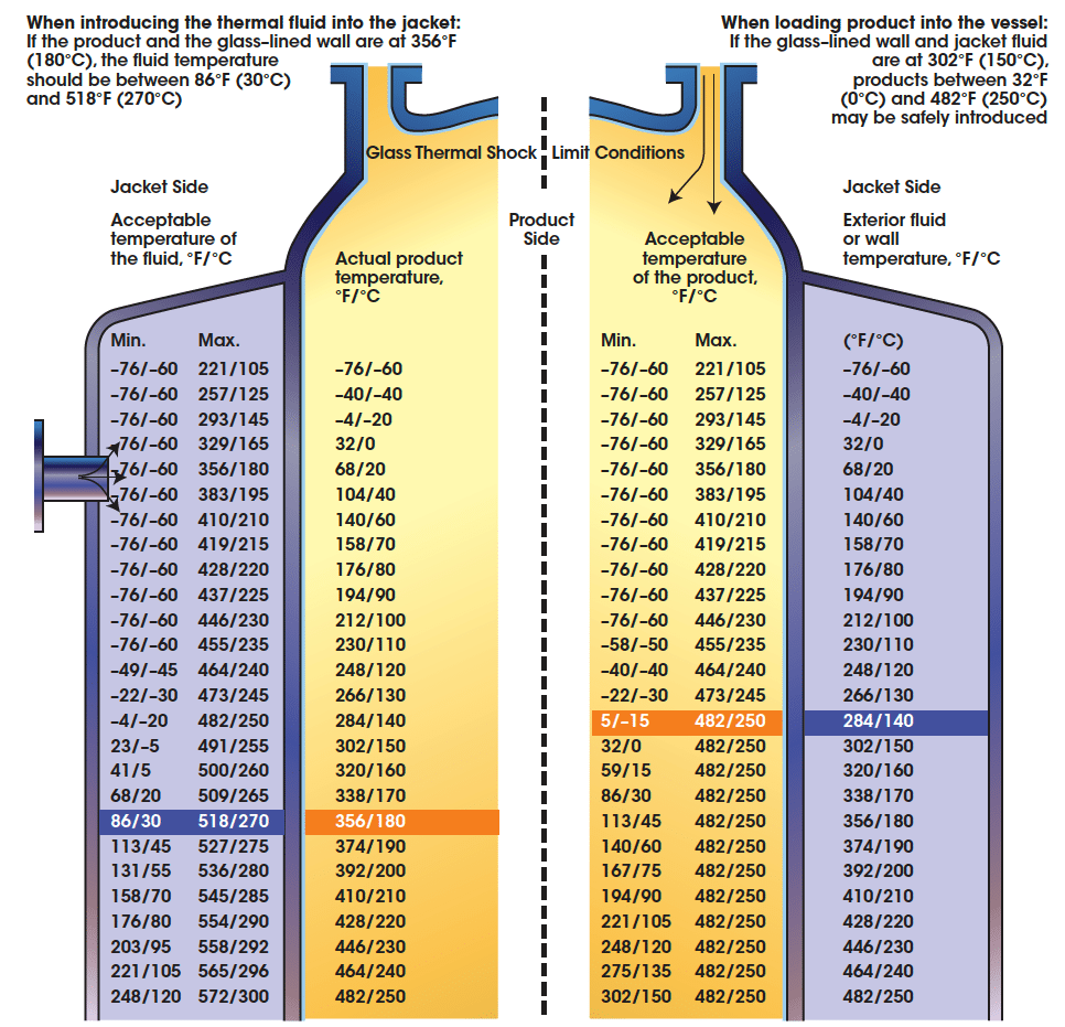
FIGURE 7. The diagram illustrates the glass thermal-shock limitations of a glass-lined vessel (for Type 3900 Glass). The values shown are within the temperature limits stamped on the vessel (Min. = minimum; Max. = maximum)
Four situations in which sudden temperature variations can cause thermal shock are when:
• Cooling a hot glass surface using a cold liquid
• Heating a cold glass surface using a hot liquid
• Heating a cold, jacketed vessel by rapidly circulating a very hot fluid through the jacket
• Cooling a hot vessel wall by rapidly circulating a cold fluid through the vessel jacket
Thermal stress. Another cause of failure in glass-lined equipment is thermal stress. Failure due to thermal stress, in contrast to thermal shock, is caused by differential heating or cooling that is not instantaneous in nature. Thermal stress may occur at areas of high stress concentration, such as on the vessel wall just below the top-jacket closure ring, or in the area where the bottom-jacket closure ring is welded to the vessel. In either case, the cause is that the area inside the jacket is heated or cooled, while the unjacketed area is not.
Preventing vessel failure
Proper operating procedures. Both thermal shock and thermal stress are strictly operational problems that can be easily avoided by following the equipment manufacturer’s recommendations. Before setting process procedures that involve thermal variations, it is important to measure (or closely approximate) the temperature of the glass lining, and to check possible local hotspots. Also, one should consult the manufacturer’s chart of maximum safe-temperature differentials and adhere to it strictly. To avoid thermal shock due to a runaway exothermic reaction, a quick-response temperature sensor may be installed in a baffle, bottom outlet valve or thermowell to warn the operator of dangerous temperature increases.
Thermal stress may be reduced by careful control of heating and cooling operations, such as by gradually raising or lowering temperatures in the jacket to minimize thermal gradients. It is also common to insulate unjacketed areas. In addition, the strapping or restraining of a jacketed vessel during heating could impede the jacket’s free expansion and result in overstressing near the closure rings.
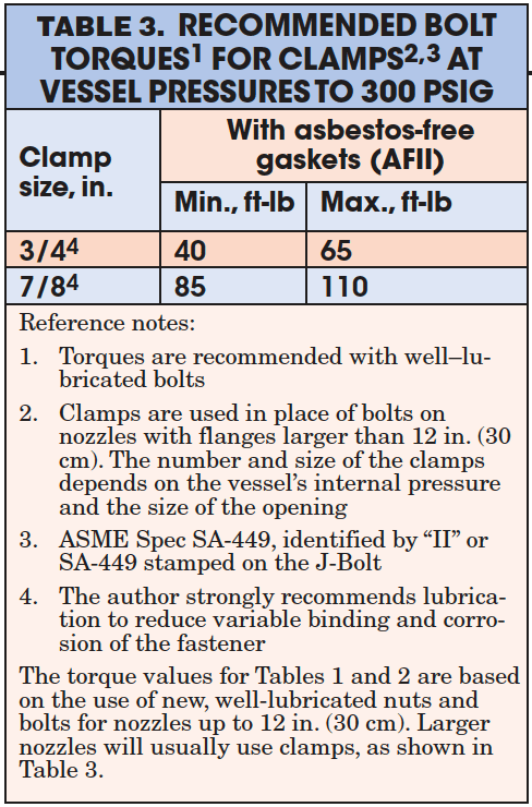
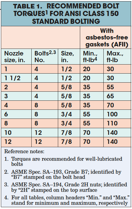
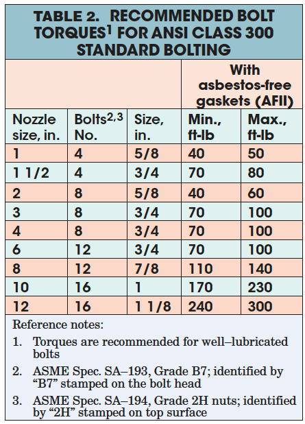
Nozzles on glass-lined vessels cannot be treated like those on unlined vessels. Two common nozzle-related causes of glass damage are excessive tightening of flange bolts or clamps and bending stress caused by piping. Tables 1–3 (click on tables below to view larger) list the recommended torques for bolts, which are usually used with nozzle diameters up to 12 in., and clamps, which are used with larger nozzles. Excessive torque can also fracture the glass on a glass-lined agitator. In this case, excessive torque occurs when an operator tries to start the agitator in a very viscous or solid mass, or if, during an operation, the vessel’s contents begin to thicken or solidify beyond design conditions. This problem may be avoided by installing a variable-frequency inverter or motor soft-start between the motor and the gear drive.
Jacket care. Jackets of glass-lined steel reactors are subject to internal fouling, due to a buildup of deposits and iron-oxide corrosion from repeated heating and cooling cycles. Over time, fouling reduces heat-transfer efficiency and increases reaction times, thereby decreasing yields by as much as 15%.
Periodic inspection and cleaning will minimize these problems and extend the life of a vessel. Cleaning compounds are available that remove iron-oxide buildup without damaging the glass lining or dissolving the base metal of a reactor. Mild fouling, especially due to the circulation of brine solutions for cooling, can be cleaned with a 15% solution of sodium hypochlorite. Acid-based cleaning solutions are not recommended because, over time, the acid reacts with the steel.
In cold climates, special precautions must be taken to protect glass-lined equipment that is used for outdoor storage or in areas that are not heated. In locations where temperatures fall below freezing, jackets must be drained and plugged to prevent water entry. Where complete drainage is not possible, anti-freeze, such as ethylene glycol, should be added to the jacket. If a split-pipe coil (or hemicoil) vessel is being used, all coils must be completely drained.
Acid spillage on the outside of a vessel causes major damage. Eventually, the acid reacts with the steel to form hydrogen, which is known as nascent hydrogen. The hydrogen atoms permeate the steel behind the glass lining until the pressure in the steel is high enough to disrupt the glass-to-steel bond and cause the glass to spall. This type of failure requires a complete reglassing of the vessel. The obvious solution is to avoid spillage, but in the event of an accident, the acid should be immediately neutralized and the exterior of the vessel should be thoroughly washed with water. As a preventative measure, the top head of a vessel may be shielded with metal or other material.
In summary, problems with glass-lined equipment can be avoided by keeping in mind the special characteristics and limitations of the equipment and by strictly adhering to a proper care and inspection program.