How big can a fermenter get? And what would the biggest fermenter look like? The answers to these questions depend upon how the requirements of heat transfer, mass transfer (gas-to-liquid), and momentum transfer (mixing) are met. In an earlier article (Heat Transfer for Huge-Scale Fermentation, Chem. Eng., November 2013, pp. 44–46) the authors described how heat-transfer requirements can cause jackets to become ineffective at large scale, which drives the need for external heat exchangers. This article examines the issues that arise with mass and momentum transfer at huge scales. The concerns associated with mass transfer at huge scales also influence the type and size of pilot- and demonstration-plant facilities that are used in scaleup.
Many useful chemicals can be produced by microbes that require oxygen to grow. An aerobic fermenter is used to grow these microbes and create the right conditions for them to produce these chemicals. This type of fermenter is essentially a mass transfer device that promotes the transfer of oxygen from gas bubbles into the liquid medium where the microbes live. Often the rate of oxygen transfer is the limiting factor in the whole manufacturing process. That is why maximum oxygen-transfer rate is a key to a successful fermenter design.
A hypothetical process
Outlining a hypothetical fermentation process, such as the following one, gives a sense of the need for huge fermenters:
Objective:Make 100,000 ton/yr of product
Assumptions:
• The final fermenter broth is 5% w/w product after 100 hours of incubation time
• Use 10% inoculum
• Seed stages incubate for 36 h with a 12-h turnaround time
• The fermenter specific gravity is equal to 1.02
• The maximum fill of the fermenter is 80%
• The maximum fermenter straight-side height is 60 ft
• The oxygen uptake rate is 100 mmole/L/h
• The fermenter turnaround time is 25 h (to harvest, clean, sanitize, fill and inoculate)
• Planned down time is 30 days for an annual overhaul, plus 15 days of contingency
• The downstream yield is 95%
Calculations:
1. Fermenter production requirement = (100,000 ton/yr)/(95% yield) = 105,000 ton/yr
2. Fermenter broth required = [(105,000 ton/yr)(2,000 lb/ton)]/(0.05 ton product/ton broth) = 4,200,000,000 lb broth/yr
3. Fermenter volumetric production = (4,200 million lb broth/yr)/[(8.34 lb/gal)(1.02)] = 494,000,000 gal/yr = 1,540,000 gal/d = 64,300 gal/h = 1,070 gal/min
4. Total fermenter capacity requirement (working volume) = (64,300 gal/h)(125 h/fermenter cycle) = 8,000,000 gal
How many fermenters would be needed to offer 8,000,000 gallons of net tank capacity? Table 1 offers some options for the number of fermenters required versus fermenter size, using the assumption that the fermenter height is limited to 60 ft.
| Table 1. Number of fermenters required for a given diameter | |||||||||||
| Fermenter diameter, ft | 10 | 15 | 20 | 25 | 30 | 35 | 40 | 45 | 50 | 55 | 60 |
| Volume, 1,000 gal w/v | 28 | 63 | 113 | 176 | 254 | 345 | 451 | 571 | 705 | 853 | 1,015 |
| Number of fermenters required | 284 | 126 | 71 | 45 | 32 | 23 | 18 | 14 | 11 | 9 | 8 |
| Harvest interval, h | 0.4 | 1.0 | 1.8 | 2.7 | 3.9 | 5.4 | 7.0 | 8.9 | 11.0 | 13.3 | 15.8 |
| Required seed fermenters | |||||||||||
| Number of seed trains | 110 | 49 | 28 | 18 | 13 | 9 | 7 | 6 | 5 | 4 | 4 |
| S-1 Seed,1,000 gal w/v | 2.8 | 6.3 | 11.3 | 17.6 | 25.4 | 34.5 | 45.1 | 57.1 | 70.5 | 85.3 | 101.5 |
| S-2 Seed,1,000 gal w/v | 0.3 | 0.6 | 1.1 | 1.8 | 2.5 | 3.5 | 4.5 | 5.7 | 7.0 | 8.5 | 10.2 |
| S-3 Seed, gal w/v | 28 | 63 | 113 | 176 | 254 | 345 | 451 | 571 | 705 | 853 | 1,015 |
| S-4 Seed, gal w/v | 11.3 | 17.6 | 25.4 | 34.5 | 45.1 | 57.1 | 70.5 | 85.3 | 101.5 | ||
| S-5 Seed, gal w/v | 8.5 | 10.2 | |||||||||
Ten-foot-diameter fermenters are known to be capable of production rates of 100 mmole/L/h and are economical, but that size would require 284 fermenters and 110 “seed trains” (see next section). It is hard to believe this would be an economical plant design. If the fermenters could be 60 ft in diameter, then there would be eight of them and four seed trains.
Seed trains: A fermentation process typically involves inoculating a batch of sterile growth media with a “seed,” which consists of viable microbes of the desired type. A 1-mL vial could inoculate a 100-mL flask, which would grow enough to inoculate a 10-L vessel, which would grow to inoculate a 1,000-L tank and so on. In this way, a production fermenter requires a series of smaller fermenters to produce a sufficient volume of inoculum. Since the seed fermenters operate in series, they are often referred to as a “seed train.”
Oxygen transfer
A fermenter’s oxygen transfer rate (OTR) is a function of the oxygen transfer driving force, the surface area across which the oxygen flows, and the resistance to oxygen transfer:
OTR = k L × a ( Cbubble–C liquid) (1)
where OTR is the oxygen transfer rate in mmol/h; k L = conductance (reciprocal of resistance) to oxygen transfer; a is the surface area of oxygen transfer in square feet; and C is the oxygen concentration.
This means that the oxygen transfer rate can be increased by increasing k L, a, or the change in C.
The effect of tank height
One of the primary constraints associated with mass transfer in fermenters is that bubbles rise only so fast. No matter how much air is introduced at the bottom, the bubbles will rise at a rate dependent on the bubble size and the liquid density and viscosity, not on the rate of air being blown into the tank. The effect is that increasing airflow increases the availability of air in the fermenter. The inventory of air at any time, the void fraction, displaces product.
For a very large fermenter with water-like fermentation broth, the average-sized air bubbles could rise at a rate of about 0.6 meters per second (m/s). That means that a superficial air velocity of 0.3 m/s results in a fermenter that is 50% liquid and 50% air bubbles. That is not a very productive fermenter.
As the gas bubbles rise, oxygen is transferred from the air to the liquid. The average oxygen concentration in the gas phase goes down with increasing height.
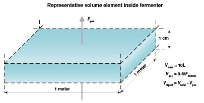
Consider a representative volume element of the fermenter that is one meter per side and one centimeter tall as in Figure 1. Assume that the oxygen uptake rate is 100 mmol O2/L/h throughout the fermenter; the superficial gas rate is 0.1 m/s (0.1 m3/s per square meter of horizontal surface); and the bubble rise velocity for this system is 0.6 m/s. The maximum fermenter height can be calculated as follows:
1. Oxygen supplied to the bottom square meter column element = [(0.1 m3/s)(1,000 L/m3)(0.209 mol O2/mol air)]/(24.5 L/mol air at 25°C) = 0.83 mol O2/s
2. The void fraction in a representative volume element = (0.1 m/s)/(0.6 m/s) = 0.17
3. The liquid volume in a representative volume element = (1m)(1m)(0.01m)(1,000 L/m3)(1 – 0.17) = 8.3 L
4. Oxygen consumed by each volume element =[(100 mmol O2/L/h)(8.3 L)]/[(1,000 mmol/mol)(3,600 s/h) = 0.00023 mol O2/s per volume element
5. The number of volume elements in column of liquid = 0.83 mol/s)/(0.00023 mol O2/s/volume element) = 3,600 elements = 3,600 cm = 36 m = 118 ft
It makes no sense to scale this process up to a height of above 36 m because the oxygen is completely depleted from the sparge air at that height. Actually, the oxygen concentration would never drop to zero, because the oxygen transfer driving force falls along with the oxygen concentration, so the top of the fermenter suffers from diminishing returns.
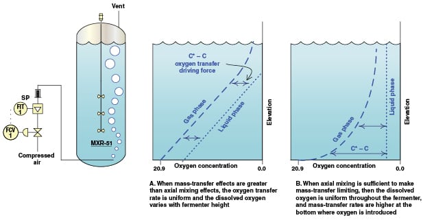
In the above calculation it has been assumed that there is negligible axial mixing of the liquid. This type of mixing in an actual fermenter (Figure 2) would serve to move dissolved oxygen that is near the bottom to upper levels where it is needed, and to move oxygen-deleted liquid that is near the top to flow downward. This movement increases the oxygen-transfer driving force near the bottom of the fermenter. However, as shown in Figure 3B, the improvement in the oxygen transfer rate near the bottom of the fermenter causes the oxygen in the gas to run out sooner.
The fermenter should not be designed as tall as 36 m, because of the very poor oxygen transfer in the upper part of the fermenter at such heights. Thus, huge fermenters need to grow fat, not tall.
High gas flowrates to the fermenter increase the number of bubbles, which increases the bubble surface area and thereby increases kL×a. In addition, with more airflow the oxygen concentration depletes more slowly, thereby increasing the overall oxygen-transfer driving force. However, since the bubbles rise only so fast, the increasing airflow will decrease the liquid volume in the tank. An increase in gas flowrate will also increase the agitator size. The more air there is, the more the impellers will have to disperse, and the higher the mixer motor power will be. This presents an interesting optimization problem. What is the optimum air flowrate?
Demonstration scale
Scaleup is about business risk. In order to evaluate the risk involved, it is important to determine what elements of the design involve performance uncertainty. An intermediate-scale demonstration plant might be required to prove that scaleup considerations are well understood. Thanks to the use of external heat exchangers, the heat transfer coefficients ( U), the effective heat-transfer area ( A), and the temperature driving forces (∆ T) are all known, so that heat ( Q) can be calculated:
Q = ( U)( A)( ∆T log mean) (2)
The above analysis shows that, for heat transfer, the design factors are already well understood and predictable, and thus present a low risk to the project. In the case of mass transfer, however, the mass transfer conductance used in Equation (1) is not well known for fermenters above about 100,000 gallons. Pilot testing is required.
Pilot-scale testing
Pilot work is critical for any new process. For fermentation applications, pilot work is required to understand how the organism will behave under specific process conditions. The information studied on the pilot scale for a fermenter must include the following: mass transfer, gas dispersion and blending. All three are of equal importance.
If the mass transfer requirements are not met, the organisms in the fermenter will die because there is not enough power available to force the liquid/gas boundary layer transfer to take place.
If the gas dispersion requirements are not met, the air is not properly distributed throughout the vessel and again, the organisms will die. If the tank is not well blended, the nutrients that are added to the vessel, the heat transfer and the pH will not be uniform. The organism will not survive in this environment. All of these are undesirable results.
The information gleaned from the pilot work is used to successfully model the full-scale operation. Pilot plant work will determine what impeller style(s), diameter(s) and power levels are required for the agitator to successfully perform.
Proper experiment set-up and execution will make sure repeatable results are achieved on the full scale. The specific parameters that must be examined are: tank geometry, baffle and coil arrangement and gas-sparging system. The tank geometry ratios, and baffle and coil arrangements should be similar between full scale and pilot scale. Pilot testing should be done with the exact process fluid to be used on the full scale, or a fluid with very similar properties. The liquid-level-to-tank-diameter ratio should be constant in scaleup, as should the type of gas and sparge system. The lower impeller should be located at a specific distance above the sparger and that ratio should remain unchanged between scales.
Traditional laboratory-scale testing is performed at a minimum volume range between 20 to 250 gal. When considering pilot scale work, a tank with a minimum volume of 750 gal, or a 4-ft-dia. × 8-ft tank should be considered.
For the 1-million-gal scale, a larger test volume would be recommended. Here, the minimum would be 10- to 12-ft-dia. vessels. A torque sensor affixed to the shaft that records data while the test is running is a necessity. Reading power using an ampere or watt meter is not recommended, especially during pilot testing. A tachometer that can accurately measure the lower shaft speed is required.
A rotameter with capabilities of adjusting the gas flowrate over a specific range is also required. At a minimum, four different gas flowrates should be examined. One gas flowrate should be the same vessel volumes per minute (VVM) as the full-scale. (VVM is a unit of gas flowrate widely used in the fermentation industry.) It will be difficult to achieve the same superficial gas velocities at full and pilot scales.
While at the pilot scale, the style and diameter of impeller(s) should be reviewed for optimum performance. A few different styles and different diameters should be available to test. The impellers should be adjustable, so that their positions on the shaft can be changed while running different experiments.
Dissolved oxygen (DO) probes should be located at the top and bottom of the fermentation tank. The probes must be kept away from baffles or other potential low velocity or dead areas within the vessel. It is also necessary to study the gas hold-up volume on the smaller scale to make sure the full-scale vessel will be tall enough to account for the increase in gas liquid volume.
Many of these points are summarized in the box on Guidelines For Pilot Plant Testing on p.46.
Final thoughts
When designing very large fermenters, care must be taken to avoid designs that are so tall that the upper portion of the fermenter is ineffective. Care must also be taken to provide adequate mixing and mass transfer in very wide fermenter designs. Since unusual tank geometry is required for very large fermenters, scaleup ratios are smaller, so large demonstration-scale testing is beneficial.
Agitation is a big expense. Using a microbe that can tolerate low or zero dissolved oxygen is highly advantageous, because of the higher mass-transfer driving force that results. Also, a microbe that does not require oxygen to produce product has a clear economic advantage by reducing agitation costs.
Edited by Dorothy Lozowski
Authors

Jim Gregory is a process engineer at Fluor Corp. (100 Fluor Daniel Dr., Greenville, SC 29607-2762; Email: jim.gregory@fluor.com). He holds a B.A. in biophysics and a B.S.Ch.E. from the University of Connecticut, and an M.Sc. in biochemical engineering from Rutgers University. He has experience in the design and operation of industrial microbiological processes ranging from human-cell-line monoclonal antibodies to diesel fuel.

Nicolle Courtemanche is a senior application engineer at SPX Flow Technology (Lightnin brand; 135 Mt. Read Blvd., Rochester, NY 14611; Email: nicolle.courtemanche@spx.com), a segment of SPX that designs, manufactures and installs engineered solutions used to process, blend, meter and transport fluids, in addition to air and gas filtration and dehydration. Nicolle holds a B.S.Ch.E. from the University of New Hampshire. Her areas of mixing expertise include, pulp and paper, biotech, pharmaceuticals and other chemical process industries.

C.R. Green (Bob) is director of design development at Fluor Corp. (same address as left; Email: bob.green@fluor.com). He holds a B.S. in mechanical engineering from North Carolina State and an M.E. in mechanical engineering from the University of South Carolina. He is a registered professional engineer in six states. Green has experience in the design and startup of microbiological processes, including human-cell-line monoclonal antibodies, amino acids, bacteria, biofuels and biochemicals.

Richard Kehn is manager of Research and Development at SPX Flow Technology (Lightnin brand; same address as left; Email: richard.kehn@spx.com). Kehn holds a B.S.Ch.E. from Rensselaer Polytechnic Institute and is pursuing an M.E. degree in mechanical engineering with a concentration in computational fluid dynamics (CFD) from Rochester Institute of Technology. Kehn has been the author or co-author of ten technical papers regarding mixing, covering low-viscosity blending, solids suspension, copper solvent extraction, slurry-tank-agitator design and CFD. His areas of mixing expertise include mineral processing, water and wastewater treatment, pulp and paper, and experimental methods including scaleup and scale-down.