The use of today’s high-performance rupture disc designs can help to reduce many common operating problems and support increased throughput requirements
Chemical process industries (CPI) plants are typically designed to achieve specific production volumes, but as anyone who has worked in one knows, those production targets are prone to change as market factors and plant objectives evolve. Most CPI facilities are expected to increase (or decrease) production targets at some point. An increase in production targets typically involves increasing the operating pressures, temperatures or both, in order to increase the rate of process reaction and the quantity of final product manufactured at the site.
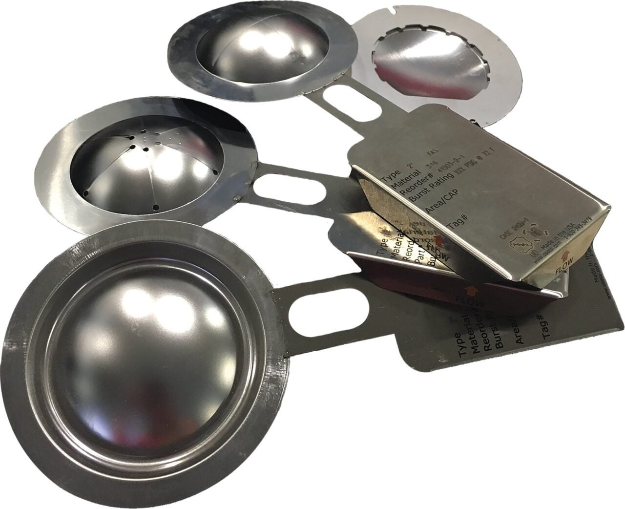
Figure 1. Rupture discs provide overpressure protection, so they play a vital role in CPI plant safety. High-performance rupture discs can maximize system efficiency and support increased plant capacity
When operating pressures are brought closer to the set pressure of rupture discs and relief valves, these changes can increase the frequency of nuisance failures, which can lead to pressure releases and shutdowns. Fortunately, pressure-relief technology has evolved over time, resulting in greater accuracy and higher performance for today’s advanced rupture disc designs.
Rupture discs are designed to protect vessels and other capital equipment from dangerous and damaging overpressurization, by bursting open and safely relieving the overpressure condition when the line or vessel reaches a pre-determined pressure and temperature. They can provide both primary and secondary relief, and are used in combination with pressure-relief valves to prevent leakage and protect relief-valve seats from potential exposure to corrosive and sticky substances.
The burst pressure is commonly set at or below the maximum allowable working pressure (MAWP) of the vessel and the temperature at which overpressure is expected to occur. In some cases, it may be desirable to set the burst pressure well below the MAWP. An increase in operating pressures means that these devices must withstand pressures closer to the expected burst pressure. Rules governing the use of rupture discs in chemical process plants can be found in ASME BPVCVIII.1-2015, Section VIII [ 1 ].
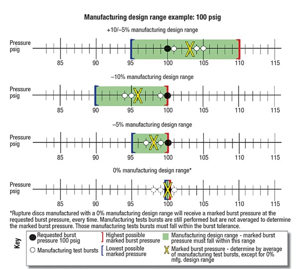
FIGURE 2. To determine the marked burst pressure, several manufacturing test bursts are run and their results averaged. The marked burst pressure on any rupture disk must fall within the parameters defined by the manufacturing design range. As shown in these examples, the marked burst pressure may be above or below the requested burst pressure, depending on the manufacturing design range available and the results of the manufacturing test bursts
Most rupture discs are manufactured from corrosion-resistant metals, using a design that is specified to meet the burst pressure and performance requirements of a given application. The user must specify the size, type, material, requested burst pressure and temperature.
The rupture disc manufacturer then manipulates the appropriate material in different ways to design and produce rupture discs that meet all of the user’s specifications. During the manufacturing process, several pieces from each lot are forced to burst as a test, to ensure that the manufactured lot meets the specifications.
Rupture discs have evolved considerably since their first use in the 1930s. Nonetheless, most of the older designs are still in use today. Compared to modern designs, older rupture disc designs have lower performance capabilities, reduced repeatability and are more difficult to accurately calibrate to a specific burst pressure.
While they may be less expensive than the newer high-performance designs, they may bring tradeoffs in performance or reliability. In many cases, a facility’s particular management of change (MOC) protocol prevents upgrading to modern technology. When this happens, users often become accustomed to tolerating the poor performance of these outdated designs.
Understanding the terms that are used to describe rupture disc performance, and the technology options that are available to meet the increasing demands placed upon these important safety devices can give engineers the tools needed to support increased production objectives at the chemical process plant.
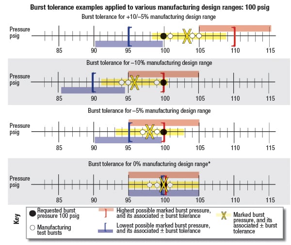
FIGURE 3. The burst tolerance is the range in which a rupture disc will burst upon activation, relative to its marked burst pressure. ASME code defines the standard burst tolerance for rupture discs as ±5% of the marked burst pressure for pressures above 40 psig. For pressures up to and including 40 psig, the standard burst tolerance is ±2 psi
Key terminology
Key rupture disc specification terms are discussed as follows: Manufacturing design range. The manufacturing design range is an agreement between rupture disc manufacturer and user that specifies how close the marked burst pressure must be to the requested burst pressure. Specifically, ASME defines manufacturing design range as follows in the Endnote 47 of Ref. 1: “The manufacturing design range is a range of pressure within which the marked burst pressure must fall to be acceptable for a particular requirement, as agreed upon between the rupture disk manufacturer and the user or his designated agent. The manufacturing design range must be evaluated in conjunction with the specified burst pressure to ensure that the marked burst pressure of the rupture disk will always be within applicable limits of UG-134. Users are cautioned that certain types of rupture disks have manufacturing ranges that can result in a marked burst pressure greater than the specified burst pressure.”
Rupture disc manufacturers typically acquire and stock a limited selection of material types and thicknesses. Early rupture disc designs had limited means of adjusting the burst pressure — other than by selecting a different material thickness. As a result, rupture disc manufacturers often were not able to achieve the exact requested burst pressure. For this reason, the manufacturing design range must be agreed upon and specified.
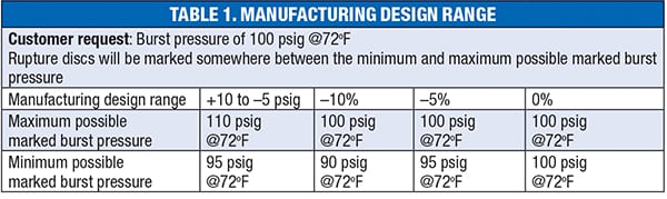
The way that manufacturing design range is expressed depends on the rupture disc brand, model and in some cases, designated burst pressure. Rupture discs may be specified with manufacturing design ranges of –10%, –5%, or 0% of the requested burst pressure, or in some cases, with a positive or negative pressure unit value (Table 1). A manufacturing range of –10% for a rupture disc with a requested burst pressure of 100 psig will be marked somewhere between 90 psig and 100 psig. Rupture discs ordered with a 0% manufacturing design range will be marked at the requested burst pressure. All other manufacturing design ranges will be marked at the average value of the test breaks that were done to qualify the lot.
Some older designs may not be available in the tightest ranges. For these designs, most manufacturers may offer a tighter manufacturing range for an added cost, while others may offer a zero manufacturing range as standard on premium rupture disc designs. Rupture discs with a zero manufacturing design range can help to minimize confusion, because the rupture discs will be marked with the requested burst pressure every time they are ordered. All other ranges are likely to have a slightly different marked burst pressure each time they are ordered, since they are marked with the average burst pressure of the rupture discs that were tested during the manufacture of that given lot.
Manufacturing design ranges that have a “plus” component (see the column marked +10/–5 psig in Table 1) may be marked above the requested burst pressure. If the requested burst pressure is set at the MAWP of the vessel, the rupture disc may violate ASME rules by having a marked burst pressure that is actually higher than the MAWP.
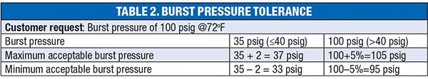
Burst pressure tolerance. As noted above, variation in materials and manufacturing processes yield slight variations in burst pressure throughout any given lot of rupture discs. ASME specifies a burst pressure tolerance of±2 psi of the marked burst pressure for marked burst pressures up to and including 40 psi; and a burst pressure tolerance of±5% of the marked burst pressure for marked burst pressures above 40 psi (excerpted from Ref. 1, Section UG-125). This means that a rupture disc marked at 30 psig can be expected to burst between 28 and 32 psig (±2 psi); while a rupture disc marked 100 psig can be expected to burst between 95 and 105 psig (±5%; Table 2). Operating ratio. Manufacturers use operating ratio to define for users the maximum operating pressure that a rupture disc can withstand while expecting a reasonable service life (Table 3). It is a measure of rupture disc performance for a particular brand and model, as determined by the rupture disc manufacturer. It is not an industry-standardized definition.
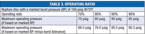
Operating ratio = Maximum operating pressure/burst pressure
Some manufacturers relate it to marked burst pressures, while others may state it as a percentage of the marked burst pressure minus the burst pressure tolerance. The way the operating ratio is defined can make a difference in the maximum operating pressure. Most modern rupture disc designs — especially reverse-buckling rupture discs — have much higher operating ratios compared to older designs.
It is important to select a rupture disc with the correct operating ratio. When the operating pressure of the system approaches the burst pressure of the rupture disc, the rupture disc material can become stressed. If this stress repeats often enough, the disc material may fatigue, and the burst pressure of the rupture disc can then become reduced as a result of compromised material strength. This can lead to nuisance failures.
Vacuum resistance. Many processes require rupture discs to operate under vacuum or backpressure. Some rupture discs are manufactured from metal as thin as 0.001 in. thick. Other designs use a polymer membrane to contain the process media and transfer the pressure load to the metal rupture disc components.
When certain types of rupture discs are exposed to vacuum or backpressure, the dome can invert or collapse while still remaining intact. The next pressure cycle will reform the dome in the downstream direction. Repeated forward/reverse cycles may result in holes, cracks and compromised material strength, leading to reduced burst pressure.
Similarly, polymer membranes can burst in the vacuum direction if they are not properly supported. Discs using a polymer membrane, or those manufactured of thin, weak material require the addition of a vacuum support to prevent damage. A vacuum support is an additional component that helps the rupture disc to resist damage by vacuum or backpressure, but opens easily with the rupture disc when the disc is over-pressured in the positive direction.
The evolution of rupture disc design The leading rupture disc designs available today are discussed below. Pre-bulged metal rupture discs —1930s design. The earliest rupture discs were manufactured as simple sheets of metal that were bolted between pipe flanges. This design was simple, but yielded relatively low performance when compared to modern rupture discs. These early rupture discs were also inconsistent, due to the limited grades of materials that were available, and the dimensional variation of the flanges used to hold them.
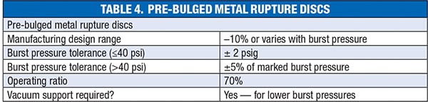
Eventually, the nascent rupture disc industry discovered the importance of installing rupture discs in precision-machined holders, to ensure accurate and repeatable burst pressures. Later, manufacturers discovered that pre-bulging the rupture discs made predicting their burst performance more accurate, and made the rupture discs more robust and easier to handle (Table 4). Pre-bulged metal rupture discs are tension-loaded, or commonly known as forward-acting, rupture discs. Forward-acting discs are pressured on the concave side of the rupture disc. The material in tension is like an inflated balloon or a loaded hammock. The burst pressure of a pre-bulged metal rupture disc is determined by its material strength and thickness. When the strength of the material is exceeded, the rupture disc bursts, relieving the overpressure condition in the pipe or vessel.
Composite rupture discs — 1950s design. Composite rupture discs are made of layers of components that serve different functions. The top layer is essentially a pre-bulged metal rupture disc that has a series of holes and slits that are punched or cut with a laser. These holes and slits weaken the disc, and add a means for further adjustment of burst pressure and much lower burst pressures than pre-bulged discs are able to reach. Because this mechanism allows manufacturers to match the requested burst pressure more accurately, this type of disc is usually available with a tighter manufacturing design range.
The middle layer is usually a fluoropolymer seal that is protected from scratches and abrasion by slit fluoropolymer layers. This seal contains the process media and transfers the pressure load to the metal top.
The bottom layer (closest to the process fluid) is usually a metal vacuum support that supports the liner when vacuum is present, but opens easily when the rupture disc bursts. There are other components and configurations available for this family of disc, but this configuration is the most common (Table 5).
Scored forward acting rupture discs —1970s to present. Scoring a pre-bulged metal rupture disc with precision tooling and specialized presses creates an even greater level of control over the burst pressure. Scored, forward-acting rupture discs usually have a cross-shaped score on the dome of the disc. This allows the disc to open with four distinct petals, without fragmenting. Some manufacturers offer 0% manufacturing range as standard. Others offer –5% or –10% (Table 6). These discs also have operating ratios as high as 90%. Scored reverse-buckling rupture discs —1970s to present. Reverse-buckling rupture discs are pressured on the convex side of the disc. This puts the dome in compression until the structure buckles. The disc does not experience permanent deformation until right at the point where the dome buckles. This makes reverse-buckling rupture discs ideal for applications that must operate close to the burst pressure, or are subject to cyclic loads. Modern reverse-buckling rupture discs are scored to create a non-fragmenting opening after the disc buckles. Burst pressure is adjusted by material thickness, dome height and sometimes by a dimple added to the dome. Most reverse-buckling rupture discs resist full vacuum (Table 7) without added support.
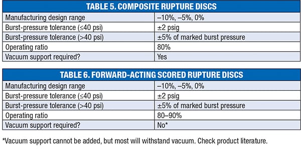
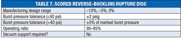
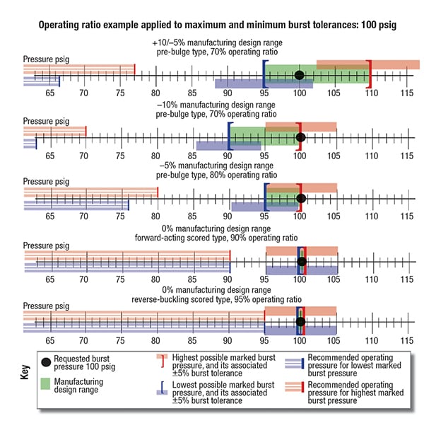
FIGURE 4. The operating ratio is calculated as a percentage of a rupture disc’s marked burst pressure. It indicates how close to the marked burst pressure the rupture disc can reliably function. The maximum recommended operating pressure can be calculated by multiplying marked burst pressure by operating ratio. This is the maximum operating pressure or the highest pressure to which the rupture disc may be operated and cycled to without causing damage of fatigue to the material integrity, and is a function of the process used to manufacture the rupture disc
Putting it all together
When determining the maximum operating pressure for a reasonable service life, we must consider all of the performance parameters together. Table 8 shows the net result of several interacting factors. Note that the maximum operating pressure is nearly 43% higher for the highest performance rupture discs when compared to the lowest performance discs.
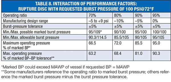
Premium scored rupture discs can cost more than lower-performance rupture discs, but as Table 8 shows, they can be operated reliably at much higher operating pressures. The increased cost of the rupture disc is often recovered through higher production rates and reduced downtime due to premature failures.
Edited by Suzanne Shelley Reference
1. ASME, “2015 ASME Boiler and Pressure Vessel Code,” ASME BPVC VIII.1-2015, Section VIII.
Author
 Alan Wilson is senior field engineer for Oseco, a manufacturer of rupture discs and other safety pressure relief devices (1701 W. Tacoma, Broken Arrow, OK 74012; Phone: 918-258-5626; Email: awilson@oseco.com). He holds a B.S. degree in mechanical design technology from Oklahoma State University, and an MBA from Oklahoma City University. Wilson has been with Oseco for 27 years, serving as an engineering expert in research and development, rupture disc analysis and ASME code. Wilson has earned several patents for his contributions to the Oseco portfolio, and sits on two ASME committees. He has helped to design, build and teach training seminar programs for the proper use, installation and specification of rupture discs in onsite learning events for chemical processing plants and others in the field. Wilson was also on the first team to coordinate with television’s Mythbusters program, when they featured Oseco rupture discs in the first of seven episodes, using them to measure explosion intensity.
Note: The discussion provided in this article does not include every rupture disc type and situation, but is representative of most rupture discs used in chemical process industries (CPI) applications. Users should always refer to the data sheets for any specific brand and model for performance specifications.