With last month’s proclamation by President-elect Barack Obama that his administration would move to cut U.S. greenhouse-gas emissions, it appears that the U.S. may finally get in step with the 182 countries that have signed the Kyoto Protocol. Obama pledged to establish a cap-and-trade system with the goals of lowering emissions to 1990 levels by 2020, then reducing them an additional 80% by 2050.
Meanwhile, in the absence of legal requirements, U.S. industry, in cooperation with foreign companies, has been busy developing and testing processes to capture CO2 from fluegas. The work is supported by the U.S. Dept. of Energy’s National Energy Technology Laboratory (NETL; Morgantown, W.Va. and Pittsburgh, Pa.; www.netl.doe.gov).
NETL’s budget for CO2 capture in fiscal year 2009 is about $40 million, says Thomas Feeley, deputy director for NETL’s Office for Coal and Power Research (Pittsburgh). In addition, industry shares at least 20% of project costs, and the Electric Power Research Institute (EPRI; Palo Alto, Calif.; www.epri.com) is spending about $5 million/yr on CO2 projects. Separately, NETL has a budget of about $150 million for research into underground storage of captured CO2.
The U.S. emitted roughly 5.8-billion metric tons (m.t.) of CO2 in 2007, according to Oak Ridge National Laboratory (Oak Ridge, Tenn.; ornl.gov). Of the total, about one-third came from coal-fired power plants.
The conventional way to scrub CO2 from gas streams is to use monoethanolamine (MEA), says Feeley, but this is not practical for power plant fluegas because of the high volume, low pressure, and the CO2 content of only 12 – 15%. Also, the solvent’s performance is degraded by other pollutants, such as sulfur dioxide, oxides of nitrogen (NOx) and oxygen. "We have found that an MEA system would require about 30% of a plant’s power production and nearly double capital costs for a new pulverized-coal plant" he says.
Technologies that are under development for CO2 control include the use of improved solvents, solid sorbents, the substitution of oxygen for combustion air, and membranes that are selective for CO2. Also, while most of the captured gas will have to be stored underground, there are plans to put some of the CO2 to beneficial use. These uses include enhanced oil recovery and the transformation of the CO2 to chemical products.
Solvents
Newer amines, designed to overcome the drawbacks of conventional solvents, are being tested by a number of companies. BASF (Ludwigshafen, Germany; www.basf.com), a leading supplier of amine scrubbing technology, is testing a new amine in a pilot plant in Esbjerg, Denmark, under the EU’s Castor program. The amine is said to be much more stable than conventional solvents, so it can be used for a longer time, and it requires less energy for absorption and desorption.
BASF also has two cooperative projects with other companies. One is with RWE Power AG (Essen, Germany) and the Linde Group (Wiesbaden, Germany) to test new solvents and CO2 scrubbing technology in a new pilot plant at RWE’s lignite-fired power plant in Niederaussem. The other, with JGC Corp. (Tokyo), is for a solvent that can remove CO2 from natural gas for reinjection underground.
Alstom (Paris; www.alstom.com) and Dow Chemical Co. (Midland, Mich.; www.dow.com) are codeveloping an advanced amine scrubbing technology for fluegas that is said to have high resistance to O2 degradation. The process is now moving from the pilot stage to a large-scale validation plant.
An Alstom process that uses ammonia as a CO2 solvent is being piloted at We Energies’ Pleasant Prairie, Wisc., power plant in a cost-sharing partnership of 37 utilities, coordinated by EPRI. In the Chilled Ammonia Process, fluegas is cooled from 50°C to below 20°C. Cooling also "drops out" water, SOx and HCl, which would react with the absorbent. In an absorber tower, CO2 is absorbed from the fluegas by an ammonium carbonate solution, forming a saturated ammonium bicarbonate solution. The solution is bled off and regenerated at about 120°C and 300 psi, releasing a pure CO2 stream.
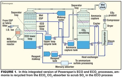
Another process that uses ammonia is being developed by Powerspan Corp. (Portsmouth, N.H.; www.powerspan.com). In the ECO2 process, NOx, SO2, mercury and fine particles are removed first, then the fluegas is scrubbed by aqueous ammonium carbonate at about 55°C. CO2 is recovered by heating the solution, and the NH3, including vapor released in the process, is recycled.
The main advantage of ECO2, is that it uses less energy than a conventional amine process. Powerspan estimates the cost of CO2 capture and compression at about $20/ton, versus $47/ton for MEA. In the laboratory ECO2, has achieved 90% CO2 capture. A pilot plant, designed to produce about 20 tons/d of CO2, started up last month at FirstEnergy’s 50-MW R.E. Burger plant in Shadyside, Ohio.
Powerspan also proclaims the benefits of combining ECO2 with the company’s ECO multi-pollutant control system. ECO (Electro-Catalytic Oxidation) is an integrated system that removes NOx, SO2, mercury and fine particles from fluegas. ECO’s wet scrubber uses aqueous ammonia to scrub SO2, producing ammonium sulfate fertilizer. In an integrated system, ammonia captured from the ECO2 absorber tower would be recycled to the ECO upper loop to scrub SO2 (Figure 1).
Potassium carbonate solution is the CO2 solvent in a process being developed at the Illinois State Geological Survey, University of Illinois (Champaign, Ill.; www.isgs.uiuc.edu). The weak affinity of CO2 to K2CO3 allows CO2 stripping at a lower temperature and pressure than an MEA process. This allows the use of low-quality steam, thereby cutting the electricity loss by 30 – 40% in a power plant installation, says Yongqi Lu, a research chemical engineer. However, the absorption rate is relatively slow, so the researchers are testing various catalysts to promote absorption.
Solid sorbents
Sodium carbonate is the sorbent in a process being developed, with DOE support, by Research Triangle Institute (RTI, Research Triangle Park, N.C.; www.rti.org). (For details, see CE, December 2008, p. 12).
DOE/NETL has also recently signed three-year contracts with three companies for the development of improved solid sorbent processes: ADA-ES, Inc. (Littleton, Colo.; www.adaes.com); SRI International (Menlo Park, Calif.; www.sri.com), and TDA Research Inc. (Wheat Ridge, Colo.).
ADA-ES heads a team that includes several power companies. The company is screening sorbents and plans to select six for field tests in a temperature swing adsorption (TSA) process. The field unit will recover 1 ton/d of CO2. In contrast with solvents, the advantage of using solid sorbents in a TSA system is that "the power requirements should be much lower because you don’t have to heat or cool a large volume of liquid," says Sharon Sjostrom, vice president, technology. The company has yet to select a process, but one candidate is a system devised by an ADA-ES team member, Adsorption Research, Inc. (ARI, Dublin, Ohio; adsorption.com). (For details, see CE, December 2008, p. 12).
SRI International is working with a carbon adsorbent from ATMI (Danbury, Conn.) that adsorbs almost 20% of its weight in CO2. Desulfurized fluegas is passed through a fixed bed of porous carbon pellets under ambient conditions. Desorption is done with steam at about 100°C. Still at the bench scale, the process is expected to have only about one-fourth the energy cost of amines, says Gopala Krishnan, associate director of SRI’s Materials Research Laboratory.
Oxycombustion
The use of absorbents or solvents can be avoided by substituting O2 for combustion air, a technique called oxycombustion. This method produces a much smaller fluegas stream that is nitrogen-free and contains 75 – 90 vol.% CO2. Part of the stream is recirculated to dilute the O2 and control the combustion temperature, while the rest is captured.
Companies developing oxycombustion processes include Air Liquide (Paris, France; www.airliquide.com); Air Products and Chemicals, Inc. (Allentown, Penn.; www.airproducts.com); Alstom, and Praxair Inc. (Danbury, Conn.; www.praxair.com).
A commercial demonstration of Air Liquide’s process is starting up at a Total S.A. (Paris) depleted natural-gas field in southern France, where a 30-MW boiler has been retrofit for oxycombustion. Air Liquide is supplying about 240 m.t./d of O2 from an onsite cryogenic plant, and the boiler will produce up to 150,000 m.t./yr of CO2. The CO2 will be injected into the depleted gas field at 50 bar for storage. Tests of Air Liquide’s process have also been ongoing since October 2008 on a 30-MWth pulverized-coal-fired boiler at the Alliance, Ohio, test facilities of Babcock & Wilcox Power Generation Group, Inc. (Barberton, Ohio; www.babcock.com).
Air Products is planning a 1-MW test of its oxycombustion process on a slipstream of a large test facility in the U.S. A key feature of the process is the removal of essentially all the HCl, SOx, NOx and other impurities as acids by a combination of compression and adding water, says Kevin Fogash, a research associate. In tests done so far the process has recovered up to 97% of the CO2 in fluegas.
A 30-MW pilot plant that employs Alstom’s technology started up in September at Vattenfall’s Schwarze Pumpe power plant in Germany. Alstom says its process captures 9 ton/h of CO2, or more than 90% of the amount generated. During a three-year trial, the captured CO2 will be used for enhanced gas recovery and storage at Altmark, Europe’s second-largest onshore gas field.
Oxy-coal, an oxycombustion process developed by Praxair and Foster Wheeler Energy Corp. (Clinton, N.J.; www.fwc.com), is scheduled to have its first commercial-scale tryout in Jamestown, N.Y. The Jamestown Board of Public Utilities plans to start up a 43-MW circulating-fluidized-bed boiler around the end of 2013. The plant is expected to capture more than 90% of the CO2.
A major cost in oxycombustion is the cryogenic air-separation plant that supplies the O2. Oxygen suppliers are working on less expensive ways to do the separation.
Alstom’s solution is chemical looping, a two-step process. First, a solid oxygen carrier is burned in air to form a hot oxide, then the oxygen in the oxide is used to burn or gasify coal. The reduced carrier is then recycled to the oxidizer. Besides avoiding the cost of a cryogenic plant, the process is said to save energy by capturing CO 2 at temperatures higher than the power cycle temperatures.
The company says it is developing a portfolio of chemical looping processes, using metal oxide- and calcium oxide-based oxygen carriers. Tests are planned for a 3-MW pilot plant in the U.S. and a 1-MW plant in Europe.
In another alternative to cryogenics, Praxair has developed a ceramic oxygen transport membrane (OTM) that is selective for O2 and has designed a boiler that has integral OTM tubes. In operation, air would be pumped through the tubes and O2 would migrate through the walls to feed combustion (Figure 2).
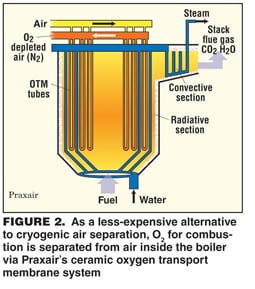 Praxair has tested a multi-tube system in the laboratory and "the continuous consumption of O2 provides the drive for oxygen migration through the membrane," says Karen Parysek, director of program development for energy R&D. She estimates that the capital cost of a power plant installation would be similar to that of a system with a cryogenic unit, but the power consumption for air separation could be 50 – 70% lower.
Air Products is also developing a ceramic membrane for air separation. Called an ionic transport membrane (ITM), it consists of complex metal oxides and is doped so that the metal oxide has oxygen vacancies. O2 is ionized and migrates through the membrane, says Ted Foster, director of business development for advanced gas separation. Once through the membrane, the O2 ions reform into molecules, releasing electrons that return to the air side to ionize O2. The air is heated to above 700°F to activate the separation, partly by compression to 280 psi and partly by burning some of the O2.
The membrane modules, consisting of stacked wafers, are designed to process 1 ton/d of O2. Foster says the process has been tested at a scale of 5 ton/d and has achieved an O2 purity of 99%. He adds that the process is "ideal for integration into an IGCC (integrated gasification, combined cycle) system," where it would save more than 30% in capital costs and 35% in power compared with a cryogenic plant.
Membranes for CO2 separation
Membranes are also being developed for CO2 separation. A new membrane is combined with a novel process design to reduce energy costs in a CO2 recovery system developed by Membrane Technology and Research Inc. (MTR, Menlo Park, Calif.; www.mtrinc.com). (For details, see CE, December 2008, p. 13).
In another membrane development, Research Triangle Institute is starting to test fluorinated polymer membranes that are selective for CO2. The plan is to build hollow-fiber modules for integration into an existing coal-fired plant.
Meanwhile, SRI International is working with a hollow-fiber polymer membrane for the removal of CO2 from syngas in IGCC plants. A pilot unit that can capture up to 250 ton/yr of CO2 will shortly be started up in a gasifier facility, says Gopala Krishnan, of SRI.
Developed by Los Alamos National Laboratory (Los Alamos, N.M.; www.lanl.gov), the polybenzimidazole membrane actually separates hydrogen from the gas mixture, leaving behind CO2. The membrane is stable at high temperatures, says Krishnan, "so we will be able to do the separation at about 250°C, which improves the efficiency of the operation."
Products from waste
As an alternative to underground storage, a number of organizations are exploring ways to make use of captured CO2. One example is enhanced oil recovery and another is algae production.
Others are working on ways to convert CO2 into useful products. Carbon Sciences, Inc. (CSI, Santa Barbara, Calif.; www.carbonsciences.com) has developed a process for making precipitated calcium carbonate (pcc), used in papermaking and in a host of products, from construction materials to toothpaste.
The conventional way to make pcc is by bubbling CO2 through quicklime, although papermills use plant fluegas says Derek McLeish, president of CSI. In place of quicklime, CSI uses calcium-rich waste streams, such as mine tailings and fly ash. The waste is mixed with water, and fluegas is passed through it at 2–10 atm. He expects the initial market will be the paper industry, where he estimates the process will be about 30% cheaper than the current way to make pcc.
CSI is also developing a process to convert CO2 and hydrogen into basic hydrocarbons — methane, ethane and propane — which can be used to make gasoline and other fuels. The key to the process is the use of biocatalysts to obtain H2 by electrolysis and to extract carbon from CO2, says McLeish.
Sandia National Laboratories (Albuquerque, N.M.; www.sandia.gov) is using a solar reactor to split CO 2 into CO and O2. The goal is to recycle CO2 and combine the CO with H2 to synthesize liquid fuels ( CE, January 2008, p.13).