Flare problems are often caused by the seal systems that are designed to control air ingress. Follow these troubleshooting guidelines to improve design and ensure safe, reliable flare operation
Flares are used to dispose of unwanted hydrocarbon gases. One common definition of a flare’s primary function is “to convert flammable, toxic or corrosive vapors to less objectionable compounds” (API 521, Paragraph 6.4.1) [ 1 ]. During operation, if the flow of offgas to the flare stack stops for some reason, there is a possibility of air ingress into the flare system. This can result in a potentially explosive mixture of air and hydrocarbons in the flare system, which can be catastrophic. To reduce this risk, many elevated flares are purged continuously with a proper amount of offgas in order to protect them against the possibility of flame flashback and explosion that could result from unwanted air ingress.
Seal systems
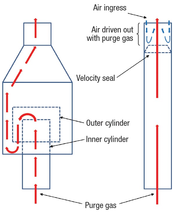
FIGURE 1. Shown here is a diagram of a molecular seal (left) and a velocity seal (right) installed in a flare stack. The molecular seal drum uses several concentric baffled cylinders to direct the exit gas and prevent air ingress. By comparison, the velocity seal is a cone-shaped obstruction (orifice) that is placed inside the flare tip, to prevent the infiltrating air from hugging the inner wall. Velocity seals require a purge rate about 2–4 times higher than that of a molecular seal
In most flare systems, either a molecular seal (also called a buoyancy seal), or a velocity seal, is used at the base of the flare tip, to ensure a minimum continuous flow of purge gas (Figure 1). This helps to avoid air ingress to the flare, preventing the opportunity for a potentially explosive mixture to develop in the system. Molecular seal systems rely on the difference in densities between the purge gas and ambient air to prevent the air from entering the flare system. The most common seal is an inverted can device that causes the gas that normally flows in an upward direction to be directed through a 180-deg turn at the exit flow. When this happens, gases lighter than air will tend to collect in the upper bend of the apparatus, sealing off the stack against any backflow of air. Meanwhile, heavier gases will tend to settle in the lower part of the bend, with the same effect. Molecular seals normally require a purge rate of 0.003 m/s to be effective. By comparison, velocity seals present a reduced diameter (such as an orifice), or a series of conical baffles, in the lower part of the flare tip, to prevent the infiltration of air. These purge-reduction devices are easily installed inside of the flare tip. The flow of purge gas (offgas) coming through the cone or baffles sweeps away the infiltrating air. This type of seal typically requires a purge rate of between 0.006 m/s and 0.012 m/s. With rising energy costs, the ability to reduce the volume of purge gas required is a high priority for many operations — as long as the safety concerns of air ingress in the flare system are not compromised. Taking this into account, it is likely that molecular seals are preferred, as they require a lower minimum required purge gas flow compared to velocity seals. In recent years, there have been many advances in molecular seal systems (in terms of both the molecular seal drum and the drain line; see Figure 2), such as drastic reductions in the purge gas requirements, and greater reliability against severe atmospheric conditions. However, one remaining drawback of using a molecular seal is the possibility of plugging in the bottom of the seal drum, due to either icing of the drain line or debris falling from the castable refractory in the flare tip (or both). During normal operation, particular attention should be paid to preventing the blockage or icing of the seal drain line — because once plugging occurs, it is too late to take proper countermeasures.
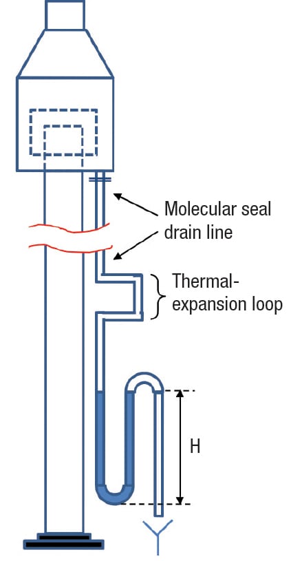
FIGURE 2. If the molecular seal drain line is not properly designed or maintained, air can enter the flare stack, causing internal combustion. If the drain line becomes frozen and does not allow the offgas to pass through, a dangerous situation can arise, leading to numerous problems in the flare and associated chemical process unit operations. As per API Standard 521 Annex D, Figure D.1, the seal height (H) should be designed for a minimum of 175% of the maximum operating pressure
The flare system is the last front line of defense for most chemical process plants. When it is not functioning properly, a malfunctioning flare system can cause the shutdown of the entire facility. One of the worst scenarios a petroleum refinery or process engineer may experience is a complete flare-system shutdown. During the design process, it is crucial to understand that it will be very difficult to add equipment, or modify and repair flare components, once the system is in operation, because flares are very infrequently out of service. And because they typically serve many process units, the unscheduled shutdown of a flare system for modification or repair will likely impact all related units. Pressure buildup in the flare header, due to problems in the molecular seal system, may lead to blockage of offgas, and this may result in the release of unburned toxic gases, which can lead to the loss of property as well as the potential for injury to personnel. The safety and effectiveness of the flare system is dependent upon the performance of the molecular seal system, which must remain free from any blockage along the offgas route, and reliably prevent air ingress to the flare system. Many flares run for long periods of time without being shut down, so the operators tend to forget important steps in the sequence. From our experience, it is interesting to recognize that most of the incidents result from a lack of operator awareness or from the fact that the facility is unattended, rather than the direct result of complex technological matters. Especially for the flare, it is very hard to detect symptoms of problems during operation, but sometimes it is too late to recover once severe problems occur. Compared with primary design aspects of the flares themselves, such as the overall flaring efficiency, proper operation of pilots, and ability to meet emissions limits, the molecular systems that are used to prevent air ingress often receive very little attention from operators, and thus their inherent importance is often overlooked. If problems associated with molecular seal systems are not detected in a timely fashion, they can lead to total process unit shutdown. Table 1 provides troubleshooting recommendations to help operators with early detection of problems in a molecular seal system at the earliest stage. For instance, by monitoring both the amount and the color of water at the bottom of the molecular seal drain line, operators can detect the earliest signs of critical failures and take action to prevent the emergency shutdown of the entire plant. 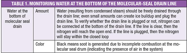
Case history examples
To help reduce the risks of fatal or unwanted shutdowns of the whole plant, this article presents three cases in which the molecular seal system failed, and provides recommendations to increase the overall integrity of the molecular seal system design in order to increase reliability, operability and the run length for the flares. It is important to learn lessons from prior failures that have been thoroughly investigated. Each of the following case history examples is characterized by the failure mode in the molecular seal system. 1. Freezing of the molecular seal drain line. In this case, freezing of the molecular drain line caused a pressure increase on the flare header, and it was beginning to approach the design limit. All of the process units that feed offgas to the flare had to prepare for potential shutdown (since none would be allowed to operate without proper waste gas disposal). When analyzing the pressure data on the header, it was found that the pressure had been relatively static for nearly a month and a half, although a slight upward trend was barely noticeable until it suddenly increased sharply (Figure 3).
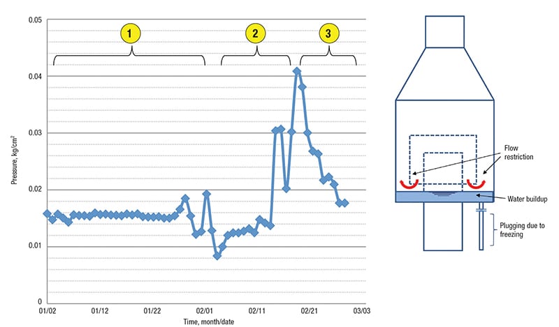
FIGURE 3. The graph (above left) shows the pressure profile of a flare header (which remained fairly static at first, but then rose suddenly). The figure (above right) shows the water buildup in the flare molecular seal. As the graph indicates, water was building up in the molecular seal drain line during the month of January (the portion of the graph labeled 1). An abrupt increase in the flare header pressure during the middle of February (graph segment 2) indicated the presence of plugging due to freezing. By March, the pressure had returned to normal, once the ice had been cleared (graph segment 3)
The abrupt spike shows that there was no gradual increase; rather, the drain line was plugged. If the pressure had been rising slowly and continuously then steps could have been taken to shut down all related process units feeding the flare. We had two options — one was to prepare an unscheduled plant shutdown, and the other was to clear the pressure buildup problem over the course of one week while the system was still operating. However, over the course of the week, the pressure could have exceeded the design limit. Unfortunately, many operators typically have no experience dealing with drain-line plugging resulting from icing. The molecular seal drain is provided to drain water that is created during operation by steam condensation. Drain line plugging becomes apparent when the drain valve is open and no water flows at all. When operators fully understand the proper function of the molecular seal system, they will respond immediately to a pressure buildup in the header by checking the drain water to discover or rule out a blockage from ice formation. But in this case, no one at the facility had a clear understanding about the plugging of the molecular seal drain line, once the header pressure began increasing. During the cold winter season, condensation will occur at both the center steam-injecion point and the upper steam-injection point at the flare tip. The center steam helps lift the flame and the upper steam enables smokeless flaring. Small parts of the center steam will condense when the shell of the flare tip is cool enough and the atmospheric temperature falls. The condensate drips down along the inside shell of the flare tip and accumulates at the bottom of the molecular seal drum. If there is no proper drainage, then this condensed water can build up, freeze and eventually block the offgas route. Upon making a close inspection all along the drain line through the stack height, there was one area (around a 1-m span out along the drain line) where the insulation had slipped away near the bottom of the thermal-expansion loop. The steam tracing was still operating, but because the insulation had slipped on a portion of it, the bare piping was still prone to icing during cold winter days (freezing temperatures of –10oC were common). In order to melt the ice buildup, the low-pressure steam was serviced through the drain line bottom connection. However, we had to spend more than two days clearing the plugged piping while the flare was still operating. Due to the limited access near the flare tip during operation, the damaged insulation could not be repaired during this effort, so we had to rely on intermittent service of steam to periodically remove the ice buildup throughout the winter season. We had to wait to repair the insulation during a scheduled turnaround, and had to spend more than $0.8 million for scaffolding work all along the 120-m stack height to access the right point. Considering the importance of the molecular seal drain line, it is important to prepare and maintain vertical piping insulation carefully. Figure 4 shows recommended specifications for proper insulation installation.
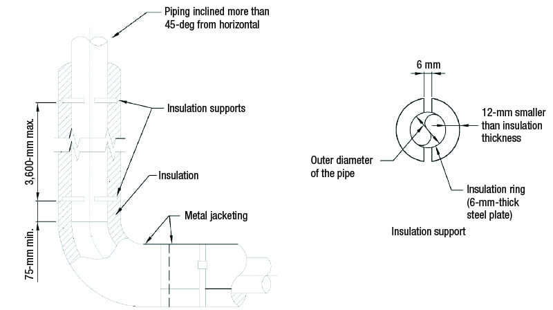
FIGURE 4. Shown here are recommended specifications for installing insulation to the molecular seal drain line. On vertical or inclined lines (more than 45 deg from horizontal), an insulation support should be provided at the bottom and every 3.6 m, where straight runs exceeds 3.6 m
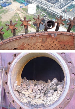
FIGURE 5. The castable refractory shown here is partially heat damaged and has become loose at the inside of the flare tip (top). The excessive build-up of refractory debris and unburned coke amounted to about half of the height of the 24-in.-dia. manhole (bottom)
2. Plugging of molecular seal drum drain-inlet nozzle. During the turnaround, we found excessive buildup of castable refractory debris and soot at the bottom of the molecular seal drum (Figure 5). Fortunately, the buildup only created a partial blockage where a chunk of debris was about half as tall as the height of the waste gas route. If the turnaround had been started at some time later than the scheduled one, we could have had a severe problem in terms of pressure buildup at the flare header. A close inspection of the debris showed that the majority was fragmented refractory pieces (an estimated 80%), and soot, iron, FeS and other materials. The castable refractory material used during the construction of flare tips must be resistant to high temperature and thermal shock. Flare tips normally experience rapid changes in temperature. Flare tips with internal refractory should also be well anchored, such as the sturdy, stainless steel hexa-mesh type. Also, it is recommended that the refractory castable material should include stainless steel needles, to help hold it in place. Even when these requirements are met, it is crucial to understand the consequences of a refractory failure, which will cause refractory debris to collect at the bottom of the molecular seal drum, blocking passageways. Whenever the refractory particles or debris fall inside the molecular seal drum, it increases the risk of plugging of the seal drain and may obstruct the flow of the offgas. To prevent the plugging of molecular seal drain lines by falling castable refractory, a plugging-protection device, such as a cap with legs, should be installed at the top of the drain hole (Figure 6). Also, during operation, the drain line should be routinely checked for plugging. One way to do this is to attach a temporary nitrogen or low-pressure steam hose to the drain line to make sure the drain line is free from refractory debris plugging. Many newer flare designs no longer use castable refractory. However, when the refractory-lined flare tip is inevitable (for instance, in older flare designs), then the size of the drain line should be increased by 4 in. or more, to reduce the risk of plugging and provide easier access for cleaning.
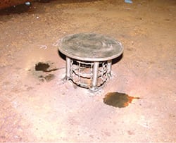
FIGURE 6. The new design of the drain cap with legs (based on bird-cage wire mesh) prevents direct plugging due to refractory or unburned
coke debris
3. Cracks at the weld joint of the molecular seal drain line.Upon making a turnaround inspection of the flare tip, we discovered significant soot buildup inside of the flare tip. Most of the buildup was soft soot but some hard coke buildup was also strongly adhered to the inside of the flare tip shell. We presume that the soot comes from internal incomplete burning, while the hard coke is produced by the high-temperature internal burning. In order to find the root cause for this internal burning, operating data for the purge gas rate and the center steam rate were evaluated. However, there were no noticeable discrepancies in the operating data compared with the design condition — they were all within the design specifications We also focused on the possibility of air ingress, which makes the flare gas burn incompletely inside the flare tip. If there were corrosion holes at the bottom of the molecular seal drum due to condensing toxic liquids, or if there were small openings at the molecular seal drain line, then atmospheric air would continuously enter the flare system during operation. With this assumption in mind, we finally discovered a relatively large gap (5-mm width with a length of more than 2/3 of the 3-in. pipe circumferential welds) between the weld joint of 3-in. molecular-seal drain nozzle and the molecular-seal drum bottom plate. Note that the 3-in. drain line at the bottom plate is a relatively small nozzle connection, so any excessive external force on the nozzle could lead to damage to the nozzle or even damage to the molecular seal drum itself. To avoid this, the allowable movement and loads at the nozzle should be designed to be zero (or as close to zero as possible; most of the movement and loads will be absorbed at the thermal-expansion loop). However, the gap was likely initiated due to some excessive external force (for instance, an external bending moment) from the molecular seal drain line. A close review of the maintenance history revealed that there had been a modification of the drain line — the original thermal-expansion loop was removed because of frequent plugging. Taking everything into account, we concluded that the root cause of the crack was excessive stress due to the removal of the thermal-expansion loops. Since this gap had allowed for continuous air ingress to the molecular seal drum, that helped to explain the longterm internal burning that had led to coke buildup during operation. Because there had been frequent plugging due to refractory debris and ice buildup, a decision was made to remove the 90-deg elbow-type thermal-expansion loop, which is the critical point of debris collection and also critical for water collection. A new thermal-expansion loop must be provided. To help reduce the risk of plugging or icing, and any such debris must be cleared as soon as it is detected, regardless of the complicated design requirements. If the drain line is straight all along the flare stack, then it can be easy for maintenance personnel to clean the pipe, even if the line is plugged or frozen. But we must consider the thermal-expansion of the drain line, which is steam-traced and insulated. It is generally agreed today that, to improve the reliability of a flare system, special considerations are required, in addition to the installation of an insulation ring with a sloped thermal-expansion loop (rather than a potentially troublesome 90-deg elbow) on the molecular-seal drain line. One way to solve this problem is to design the thermal-expansion loop with a 45-deg elbow instead of 90-deg elbow, to reduce the opportunity for any debris or water collection at the low point (Figure 7).
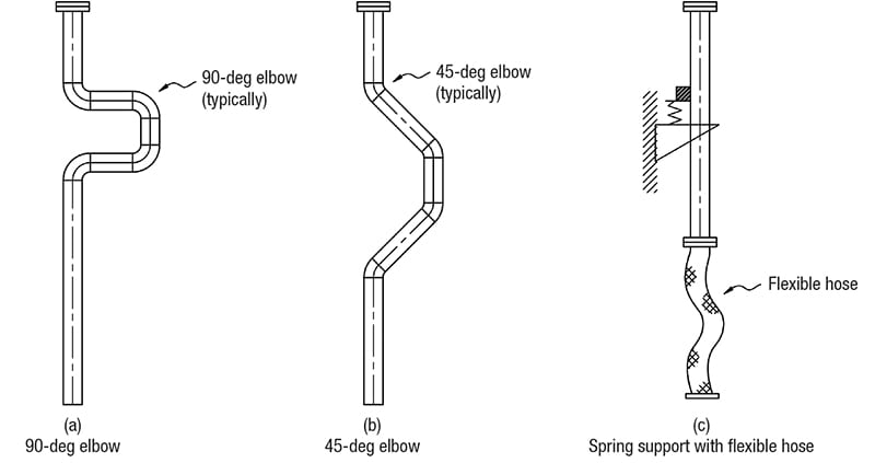
FIGURE 7. To reduce the likelihood of ice and debris formation, any thermal-expansion loop that has a 90-deg elbow, such as that shown in (a), should be modified into either a 45-deg elbow type (b), or a newer design that uses a straight line with spring support at the top and flexible hose at the bottom of the drain line (c). The 90-deg loop has additional disadvantages, in terms of potential sagging at the horizontal piping, which results in plugging of the pipe
Another way to reduce the piping stress is to consider the use of a spring hanger (which helps to reduce or eliminate the external force from the piping) near the drain nozzle. The straight drain line is resisted by the spring hanger at the top of the drain nozzle of the molecular seal drum, and the drain line at the bottom is connected with flexible hose, which can absorb some thermal expansion and also can make it easier to carry out steam blowing or cleaning.
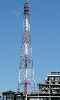
FIGURE 8. The ability to eliminate air ingress through proper engineering design and ongoing maintenance and troubleshooting is an important factor in optimizing the reliability and safety of flare systems
Molecular seal drums are commonly made of low-carbon steel, therefore, the bottom and wall are subjected to corrosion due to the formation of condensate with corrosion particles from the off-gas. In this regard, the molecular seal drum often requires preventive repairs, as well as periodic checks of wall thickness, and removal of condensate and refractory debris from the bottom. In order to improve the strength of the molecular seal drum, an ellipsoidal-type bottom head can be considered instead of the conventional flat-plate type. This design provides improved strength of the weld joint, as well as less plugging due to the configuration of the ellipsoidal head. Although most flares (Figure 8) actually operate at a pressure less than 15 psig, it is not usually necessary to consider the molecular seal drum as a pressure vessel. Typically for this design, the rules of the ASME Boiler and Pressure Vessel code [ 5 ] can be applied, and can be used as means to ensure fabrication quality. In order to improve operating safety, protect personnel and the environment, and avoid costly shutdowns, it is critical to design, operate and maintain molecular seal systems properly. The failure cases discussed here provide useful insight for improving the design in order to reduce losses and prevent shutdowns and flare outages. Edited by Suzanne Shelley
References
1. American Petroleum Institute, Guide for Pressure-relieving and Depressing Systems, API Recommended Practice 521, 6th Ed., January 2014.
2. American Petroleum Institute, API Standard 537, Flare Details for General Refinery and Petrochemical Service, API Standard 537, Draft 3rd Ed., Sept. 2001.
3. John Zink Co., “The John Zink Hamworthy Combustion Handbook,” Vol.3, Applications, Chapter 11: Flares, CRC Press LLC, 2001.
4. Shore, David, Making the flare safe, J. Loss. Prev.Process Ind., Vol. 9, No. 6, pp. 363–381, 1996.
5. ASME, ASME International Boiler and Pressure Vessel Code, Sec. VIII, Div. 1, Pressure Vessels, 2015 Ed.
Author
 Hyunjin Yoon is a master engineer of fired equipment at SK Energy (2, Sinyeocheon-ro, Nam-gu, Ulsan 680-130, South Korea; Email: hj.yoon@sk.com; Phone: +82-10-3570-0106). He received an M.S. degree in material science and engineering from Stanford University (Palo Alto, Calif.), and a B.S. in mechanical engineering from Hanyang University in South Korea. Yoon has more than 27 years of petrochemical industry experience. He has broad experience in fired-equipment design, troubleshooting and maintenance. He is credited with major roles and involvement in the development of specifications and various maintenance procedures for stationary equipment.