The inherent characteristics, requirements and special concerns of pilot- and laboratory-scale distillation columns differ from those of commercial-scale equipment. The scale-related differences of distillation assemblies are presented here
Distillation processes at any scale share many of the same theoretical and practical concepts and concerns. For example, pressure has a similar effect on operating temperature and component vapor-liquid equilibrium. And a specific number of theoretical stages, feed location, feed temperature, reflux ratio, and distillate-to-feed ratio will result in a similar component separation for a given feed composition, column head pressure and differential pressure.
Further, at any scale, vapor and liquid contacting is generally accomplished by trays, random packing or structured packing. Reboilers are usually based on kettle, thermosiphon, or pump-around designs that employ steam, hot oil or electric elements for their heat source to generate vapor. Updraft or downdraft-style condensers are required to condense all or part of the overhead vapor stream. Vacuum or pressure-control systems are required to operate a distillation column below or above atmospheric pressure. Input sensors, pumps and control values are required on most distillation columns.
However, the scale of the equipment has a major influence on its design, construction and operation. Pilot- and laboratory-scale distillation columns have inherent aspects, requirements and concerns that differ from commercial-scale columns. This article highlights the specific concerns imposed on the purpose, design and operation of small-scale distillation equipment, and discusses how these concerns manifest themselves in the actual equipment that is typically used. It also offers unique ideas that have been presented for small-scale equipment. Although this paper is focused on the scale-related differences of distillation columns, many of these concepts apply to other unit operations.
Challenges of scale
The following list summarizes the main concepts that affect the design of small-scale distillation equipment:
• Certain engineering concepts require a different emphasis or must be implemented in a different manner
• Equipment design, type and availability is different than for commercial-scale
• The main purpose of small-scale systems is usually to collect data, but sample generation is sometimes important
• Facilities in which the distillation equipment is housed must have wide-ranging capabilities to be able to accommodate physical dimension (especially height) requirements, and personal exposure, flammability and reactivity concerns
• The life of the small-scale distillation equipment setup is usually short-term
• Ease of modifying equipment or operation is important
Surface-to-volume ratio is a key engineering concept for certain aspects of small-scale equipment, and is more of a concern than for large-scale equipment. This concern applies to heat loss, column-wall effects related to mass transfer and vacuum leaks.
Heat loss. Heat loss is a critical concern for distillation columns. For columns above ambient temperature, wall condensation occurs; for columns below ambient temperature, wall boiling occurs. Wall condensation and wall boiling are important because they change the liquid-to-vapor ratio of the flows within the column, and because they have an effect similar to changing the reflux ratio (although heat loss causes a continuous variation in the flows and ratios throughout the column). This effect causes the liquid-to-vapor ratio to be different than expected, based on the apparent reflux ratio (measured by the reflux-to-distillate ratio at the top of the column) and results in a separation that is different than intended. In addition, for packed columns, there could be significantly different flows across the column radius.
Column-wall effects. Column-wall effects are more significant in small-scale columns than commercial-scale units due to the enhanced surface-to-volume ratio. This phenomenon can increase the amount of surface area for mass transfer in a packed column, can provide a path for liquid channeling, which decreases the liquid available for vapor-liquid interaction, and can lead to axial dispersion. These effects can cause the resulting separations to be different than expected based on the inherent characteristics of a given packing. This is especially important because the goal of the smaller equipment is often to model a larger column.
Vacuum leaks. Vacuum leaks are a larger problem in small-scale columns, since the sealing-surface-to-column-volume ratio is larger, so there are more opportunities for leaks. Excessive leaks can prevent the desired operating pressure from being achieved, causing light components to be swept from the condenser to the vacuum system, and, in severe cases at high vacuum, significantly increase the vapor flowrate.
Some instrumentation and control devices used for small-scale distillation columns are similar to those used for commercial-scale units, such as pressure, differential pressure and liquid-level instruments. However, flowmeters, valves and pumps must be able to work with low flowrates at a wide range of process conditions. It is often difficult to accurately measure and control low flowrates, and the small-diameter tubing and orifices required can lead to plugging problems.
Packing and trays have minimum column diameters that will allow them to generate representative data that can be used for simulation validation or scaleup. For random packing, the rule-of-thumb is that the column diameter should be at least eight times the packing-piece diameter. In some cases, this ratio can be smaller. For example, with Pro-Pak packing, this ratio is about six. Structured packing has similar constraints based on the packing crimp size. For Oldershaw-style trays, the minimum diameter is about 19 mm. Below this diameter, the hole pattern on the tray deck becomes non-representative, and the small diameter of the downcomer causes problems with vapor-liquid disengagement. Also, the liquid flow suffers from surface tension effects.
For small seals and joints, the choices are often limited to those that are the correct size and can accommodate the pressure, temperature and chemical compatibility requirement for both glass and metal.
The purpose of small-scale distillation columns is usually for the collection of simulation-validation or scaleup data. Additional instrumentation is often required, such as an enhanced number of column thermocouples, for control or to observe the column temperature profile. More sample points may be required, and sampling frequency is normally higher than for a commercial operation. Often, it is important to use glass distillation columns so that tray activity, process fluid color, foaming issues or fouling problems can be observed.
The following sections will provide details about equipment and tools that are used to address many of the concerns discussed above.
High-vacuum operation
For distillation under vacuum, differences between small- and large-scale distillation units include methods of sample collection.
Distillate and sidestream recovery. The traditional means of collecting distillate from a small-scale distillation column is using a glass double-bulb receiver (Figure 1). During normal operation, a vacuum pump maintains the column and both bulbs of the receiver at the same pressure. Condensate flows continuously and by gravity into the upper bulb, then down to the lower bulb. When the lower bulb has become sufficiently filled, it will be isolated by valves so that condensate continues to flow into the upper bulb. The vacuum on the lower bulb will be released, which allows its contents to be drained. The lower bulb is then re-evacuated to the same pressure as the column and the upper bulb and the valve between the bulbs is opened to allow condensate to once again flow from the upper to the lower bulb.
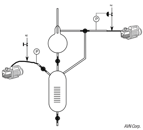
FIGURE 1. A double-bulb receiver, such as the one shown in the diagram, receives distillate in a small-scale setup
This system for distillate collection works well for many small-scale vacuum-distillate columns. The equipment requirements are minimal, and it is easy and fast to assemble. However, it is prone to column pressure “bumping” if the lower bulb re-evacuation is not done properly, and this design does not allow for unattended operation.
As an alternative, for some small-scale distillation columns, a system for distillate collection is utilized that is typical of that used for commercial scale (Figure 2). Condensate flows into a surge vessel, which has a liquid-level instrument that controls a pump. The pump flowrate is adjusted, based on the liquid-level instrument, to maintain a flowrate that is equal to the condensate rate. The pump also pumps from vacuum to atmospheric pressure. This system allows for automated operation and avoids upsetting the column pressure. However, it requires additional equipment, and there may be pump-priming issues.
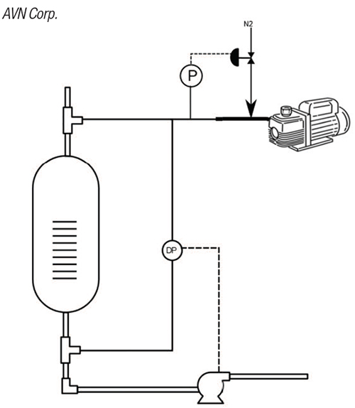
FIGURE 2. This small-scale system uses a distillate-collection design similar to a commercial-scale unit
These two methods can also be used for the collection of sidestreams. However, care must be taken with regard to the vent system. The pressure at the sidestream will be higher than at the top of the column due to the pressure drop in the trays or packing, so the sidestream liquid-takeoff point on the column must be vented to the column at that location. A nitrogen blowback system may also be required to avoid the escape of vapors from the column. This involves feeding nitrogen into the instrument line at a superficial velocity that is sufficient to prevent the flow of condensable vapors from entering this line from the column in order to prevent measurement errors.
Sample collection from the kettle. Small-diameter continuous distillation columns will normally require a pump to remove the tails stream from the reboiler, which is often a round-bottomed flask with a heating mantle. Ideally, the height to which the liquid must be lifted is minimized and the line diameter is large enough so that pressure drop is negligible, since the liquid is at its bubble point and may flash in the pump inlet line. This concern becomes even more important if the column is under vacuum.
If the column is operated in batch or semi-batch mode, a continuous tails-removal system is not required. However, there may be the desire to collect periodic reboiler samples. One way to accomplish this is with a receiver that is connected to a vacuum pump. If the melting point is above ambient temperature, then heat tape or heat jackets will likely be required. Figure 3 shows an example of a vacuum-sampling system for a reboiler in which the contents have an elevated melting point.
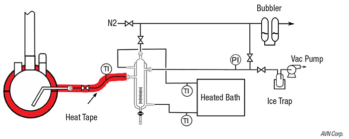
FIGURE 3. The apparatus to sample high-melting-point materials under vacuum is shown here
In a later section, other sampling topics are discussed, including sampling from column packing or trays, and the collection of low-flowrate condensate streams.
Heat control
Heat loss or gain in a distillation column is a major concern, since it affects both the liquid-to-vapor ratio and the flowrates. Therefore, it impacts the separation and column capacity. This issue requires more attention for small-scale distillation columns than for commercial columns due to the much higher surface-to-volume ratio of small-scale columns.
Vacuum jacket and silver. For glass columns, a common type of insulation is vacuum jacketing and silvering (Figure 4). The use of a vacuum jacket reduces heat loss from conduction and convection, while silvering reduces heat loss by radiation. Narrow windows located in the front and back of column sections allow for visual inspection of tray activity. Since the temperature of the distillation column wall will normally be higher than the outer wall of the jacket, glass bellows are incorporated into the column wall to allow the inside tube to expand relative to the outside tube. Bellows can accommodate reasonably high temperature, but can crack if the column temperatures become excessive.
FIGURE 4. The photo shows a glass feed section with vacuum jacket and silvering. (Courtesy of Surplus Components, Granite Falls, Minn.)
Tapered ground-glass joints are common on glass column sections and the vacuum jacket is often extended to include the tapered joint. However, this design shows much heat loss at the joint, which is the main source of heat loss in column sections. Another concern about tapered joints is that they can become frozen, making it difficult to free the column sections from each other; Teflon sleeves are often used to help prevent this. Vacuum grease is also commonly used, although this can contaminate the process if too much is used. This is a common mistake, and practice is required on applying it correctly. The socketed nature of these joints presents some potential disadvantages: column modifications usually require disassembling the column; vacuum leaks are sometimes hard to fix; and column alignment is more difficult.
Vacuum jacketing allows for rapid assembly of laboratory-scale distillation columns. However, care must be taken in their assembly, mounting and use. These sections are relatively delicate and are prone to breakage. They must be carefully mounted so that uniform pressure is applied by the supporting column clamps, and a sufficient number of clamps must be used to minimize downward force on any of the column sections.
Vacuum-jacketed glass sections have the potential to implode, resulting in glass shards being projected in every direction. To prevent potential injury, these sections must be wrapped in plastic mesh or coated with transparent plastic. More commonly, the glass bellows can develop cracks, allowing the vacuum, and its insulation capability, to be lost. If a vacuum-jacketed column section feels hot during normal operation, this indicates that the vacuum may have been compromised.
For some chemical systems, solids may build up in the trays. If not for the silver coating, the column sections can often be heated in ovens used for glass annealing to burn out the solids. However, this will destroy the silvering and require that it be reapplied by the supplier.
One possible alternative is to have a non-silvered jacket that can be evacuated with a vacuum pump. This allows the column section to be heated to a high temperature in an oven to burn out polymer, where traditional silvering would be destroyed and thermal stresses on a thin-wall vacuum jacket may lead to breakage. To minimize radiant heat losses, reflective nickel foil can be wrapped around the jacket. Traditionally, glass vacuum jackets are made with bellows that allow for the expansion of the hot inner process tube relative to the cold jacket. If bellows are not installed in the jacket for the non-silvered alternative, the maximum operating temperature for the column section will be limited to 150°C or less.
Vacuum-jacketing works well for columns that will not need to get too hot or have too many joints, as well as those columns for which the main purpose is to produce product, usually for sample quantities. A significant amount of heat loss can occur from the joints in hot columns. A rough guideline is that it is not recommended to validate simulation models using vacuum-jacketed columns when the temperature is above 120°C, and the column has more than four joints, not counting the connection to the condenser. In this case, one should consider the solution discussed in the next section.
Heat tape and insulation. Metal columns normally do not have jackets. Glass columns can be purchased without jackets to reduce the cost or to allow the columns to be burned out, as discussed earlier. Otherwise, the amount of heat loss that would occur from a vacuum-jacketed column would be unacceptable due to the high temperature and large number of joints usually present with a tall column. In these cases, the use of heat tape and insulation is a technique that allows a small-scale distillate column to operate at near-adiabatic conditions [1].
This technique can be used for unjacketed glass and metal columns. It involves wrapping each column section with two layers of insulation and wrapping heat tape between the insulation layers. A thermocouple should be inserted near one of the heat tapes and another thermocouple should be located within the column to measure the process temperature. If the process temperature is not available, a thermocouple can be placed on the outer wall of the column. During operation, the heat input from the heat tapes is adjusted so that the two thermocouples read the same temperature, indicating that there is no heat flow into or out of the column. Figure 5 shows a conceptual diagram of this technique.
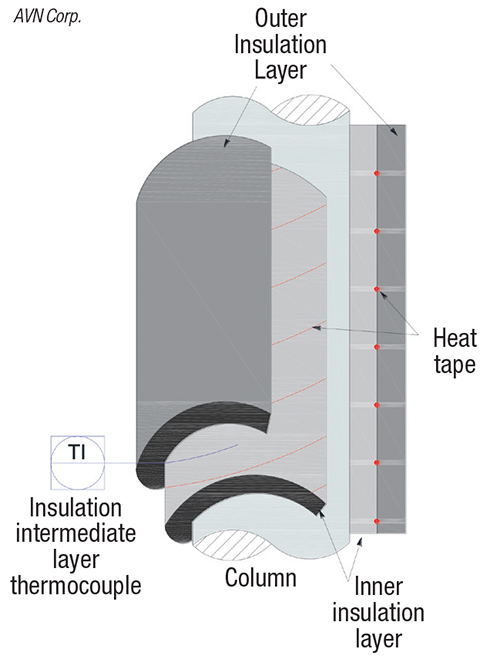
FIGURE 5. The diagram shows an unjacketed distillation column with insulation and heat tape. (Copyright R. Nunley, Matric. Used with permission)
For columns with significant temperature profiles, multiple zones are required. Each zone will represent one or more heat-tape sections, and each of these sections will operate at a different temperature. The goal is that the temperature of each heat-tape zone is equal to the average process temperature within that zone. Any given point in a column section may not be exactly adiabatic, but the average of the heat loss and gain for that zone will be near zero.
In addition to the extra effort to wrap the column sections with heat tape and insulation, the process control system for this type of a setup is more complex due to the need for thermocouples and heat-tape controllers, as well as the required configuration of the control system and the connection of the control system to the heat tapes.
Heated enclosure. Another means of minimizing heat loss is to operate the distillation column inside a heated enclosure. By reducing the temperature difference between the process within the column and the external ambient temperature, glass vacuum-jacketed column sections may now be acceptable, whereas they may have experienced too much heat loss at the original room temperature.
One of the main advantages of using a heated enclosure is for chemical systems with high melting points. However, it is usually difficult to heat tape or trace all the process lines in a way that avoid all cold spots. Also, during column startup, the vapors initially rising in the column are exposed to cold surfaces, which can cause freezing to occur within the column.

FIGURE 6. The batch distillation column in the photo is surrounded by a homemade Plexiglass enclosure with heat guns
Figure 6 shows a “homemade” Plexiglass enclosure for a 1-in. diameter glass distillation column, heated by two heat guns, with the capability to operate at temperatures up to 60°C. Figure 7 shows an example of a larger, commercially available enclosure.
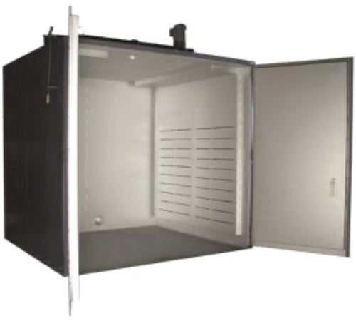
FIGURE 7. This photo shows a commercially available heated encloser for larger systems. (Courtesy of Benko Products, Sheffield Village, Ohio)
If the column is manually operated in a heated enclosure, the upper temperature limit is determined by human limitations. Also, any instruments within the enclosure must be able to operate at elevated temperatures. Feed tanks and receivers may need to be located near the column, so this needs to be accounted for regarding the size of the enclosure.
Vacuum vessel. For distillation columns operating below ambient temperature, a vacuum vessel can be used (Figure 8). For this system, the distillation column and associated piping and instrumentation are located inside of a vessel that can be evacuated by use of a vacuum pump. This eliminates heat gain by convection and conduction, and radiation effects are normally negligible at these conditions. If that is not sufficient, it is also possible to line the vessel with multi-layer insulation. This is the approach used in some small cryogenic nitrogen plants.

FIGURE 8. Vacuum vessels, like the one in the diagram, can be used for low-temperature distillation columns
The main difficulties with this system have to do with the assembly and mounting of the column within the enclosure, sealing of the piping and instrument line penetrations, the necessity of complete automation of the column, and sealing of the vessel shell. In Figure 8, all the penetrations are below the vessel flange, so it can be removed to work on the equipment.
This approach can also be used with distillation columns operating at very high temperature or with compounds with high melting points, in which heat taping or tracing may not be practical. In this situation, prevention of heat loss by radiation may also be required.
Reflux control
Several approaches are available for controlling the reflux ratio in smaller-scale distillation units, as discussed in this section.
Liquid dividing head. The typical way to control the reflux ratio for small laboratory columns is by using a liquid dividing head. Numerous designs for this device exist, and the main principle of operation is that all of the condensate is directed to the reflux return or to the distillate-producing line for a specific period of time (usually in the range of 2 to 3 seconds for the minimum time period). Therefore, the reflux ratio is determined by the ratio of time, rather than by the ratio of flowrates, as for a commercial column.
Figure 9 shows a liquid dividing head with a swinging bucket. This device would be located between the top of the column and an updraft condenser. The condensate drains into the swinging bucket, whose movement is controlled by an electromagnet connected to a timer. When the electromagnet is turned on, the swinging bucket is pulled into the distillate position, in which the condensate is directed to the distillate line. When the electromagnet is off (reflux position), the condensate is allowed to drain to the top of the column.

FIGURE 9. This liquid dividing head reflux splitter is equipped with a swinging bucket to collect distillate
These devices are relatively simple, with the only moving part being the swinging bucket. No pumps or flowmeters are required, which is very beneficial at the low flowrates characteristic of laboratory and small pilot columns. Highly accurate reflux ratios, down to a value of about 0.5, can be achieved if the swinging bucket moves quickly and is controlled by a precise timer.
It is important that the magnet be mounted next to the liquid dividing head so that the swinging bucket is pulled straight out and not to one side of the other, which can bind the hinge or slow the movement. For reflux ratios of 1.0 and greater, the off-time (distillate) should be set at 2–3 seconds. Less than this amount of time introduces error from the switching time. More than this amount of time allows the top tray, or top of the packing, to begin to dry out. Reflux ratios below 0.5 will also tend to dry out the top of the column. In addition, this requires an electromagnet that will not overheat when energized for most of a reflux cycle. To resolve this problem, it is possible to purchase reverse liquid dividing heads, in which the distillate position corresponds to the electromagnet being de-energized. Some electromagnets have been built with cooling capability.
Another concern is polymerizable chemicals. Vapor can condense, uninhibited, on the swinging bucket hinge, polymerize, then cause the hinge to seize. In general, it is good practice to check on a regular basis that the swinging bucket is operating properly.
Three-way valve. For metal columns or larger glass columns, liquid dividing heads are less practical, and are difficult to obtain. An alternative technique, which operates according to the same principle as the liquid dividing head, is based on a three-way valve that can be actuated by a solenoid (Figure 10). As with the liquid dividing head, the reflux ratio is controlled by a timer, which, in this case, is connected to the three-way valve. Either an updraft condenser, as shown in the figure, or a downdraft condenser, can be used. It is important to balance the pressure on each side of the three-way valve so that the condensate flows at the same rate in both the reflux and distillate positions.
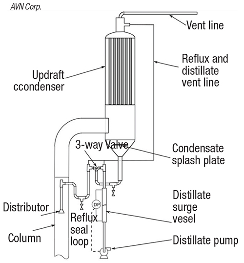
FIGURE 10. The reflux splitter shown here has a three-way valve to divert the distillate
Reflux pumps. For a system similar to what would be implemented in a commercial-scale column, it is also possible to use calibrated metering pumps, shown schematically in Figure 11, or a pump with control valves and flowmeters to control the reflux ratio. A surge vessel with a liquid-level instrument is also required. This is usually used to control the distillate rate. The reflux rate would be controlled at a fixed flowrate.

FIGURE 11. Calibrated metering pumps can be used in reflux splitters to control the reflux ratio
This system allows for a wide range of reflux ratios and works well with automated distillation columns. The possibility of a pressure bump, described earlier, is greatly reduced with this system. However, it is more expensive and requires additional effort to set up.
Fixed reflux ratio. In some cases, the operating temperature of the column may be very high, making it expensive and difficult to use the equipment discussed previously. In addition, the pressure may be high, complicating the situation even more. If the reflux ratio can be fixed at a specific value, one possible solution is to design a liquid distributor in which the condensate is split at a constant ratio, into the reflux and distillate. This requires no moving parts or seals, and would be relatively inexpensive. The main concern would be verifying that the distributor splits the flow as expected, usually with water tests, similar to what is used in large-scale distillation columns.
Product takeoff
Removing sidestream products is often an important aspect of smaller-scale distillation columns. Several considerations are discussed here.
Liquid sidestream. The liquid dividing heads described above can also be used for liquid sidestreams. The concepts are the same as for the collection of distillate, except that the pressure must be balanced between the vapor and liquid for the sidestream make line. Otherwise, either vapor will blow out the sidestream make line or the sidestream liquid will be prevented from flowing.
As an alternative, a special column section can be used that collects liquid in an annular cup. The cup must be connected to a pump that can then continually remove sidestream product from the column.
One advantage to using a liquid dividing head to collect a liquid sidestream is that it provides an indication of the liquid flowrate below the sidestream takeoff point, since the reflux timer controls the ratio of the reflux and sidestream flowrates.
Vapor sidestream. Figure 12 is a schematic diagram for an apparatus to remove a vapor sidestream from a small-scale distillation column. The column section that allows vapor to flow out of the column can be a repurposed feed section or a relatively simple glass piece made for this purpose. The vapor is maintained above the dew point by heat tapes prior to flowing through a control valve. The discharge from the valve flows into a downdraft condenser, and the condensate drops into a surge vessel. A liquid-level instrument then controls a pump connected to the bottom of the surge vessel. The surge vessel must operate at a lower pressure than the column to provide pressure drop across the valve.
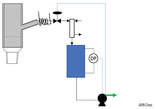
FIGURE 12. The diagram shows how to remove vapor from a sidestream with a control valve
An alternative design is to use a flooded condenser that doubles as a surge vessel. If the pump rate is slow, the vapor will flow into the condenser, and the condensate will gradually fill the condenser, cover the cooling surface, and slow or stop the condensation and vapor flow. When the pump rate is increased, the liquid level will decrease and expose more surface for condensation.
Low-flowrate vent condenser. For some laboratory columns, the main condenser may be a partial condenser, in which case the vent stream contains a small amount of condensable material. Figure 13 shows an apparatus that can be used to condense and collect this material from the vent stream, and accurately determine the flowrate, even if the rate is as low as 4–5 mL/h.

FIGURE 13. A condenser-receiver, like the one shown here, can be used for low-flowrate condensate
The device consists of a jacketed vessel for coolant. A large-diameter dip-tube extends halfway down the vessel. This ensures that the vapors entering from the top of the vessel contacts the cooling surface but leaves adequate volume in the bottom for the condensate.
For operation at atmospheric pressure, the condenser-collection vessel can be simply drained. If the column is operated under vacuum, a lower receiver, which can be evacuated by a vacuum pump, is connected to the bottom of the upper vessel, as shown in Figure 13.
Reboilers
The following describe different types of reboilers for small-scale distillation units.
Round-bottomed flask with heating mantle. The round-bottomed flask is the typical reboiler used for laboratory-scale 1-in.- and 2-in.-diameter columns. Figure 14 shows an example. They are simple, easy to install and work well for batch distillation columns, but can also be used for continuous columns with the addition of a port for liquid takeoff (for tails).

FIGURE 14. The round-bottomed flask is used as a reboiler, with a heating mantle
However, the low surface-to-volume ratio prevents the use of glass round-bottomed flask reboilers for most larger columns due to the lack of sufficient heat-transfer surface area. In addition, the reboiler residence time may be too long, especially for larger flasks, and promote decomposition of materials for some chemical systems.
For high heat input, the temperature difference across the flask heating surface can become too high for the integrity of the glass. Boiling chips are routinely used, due to lack of agitation, which work reasonably well, but bumping is possible, especially under high vacuum. However, an agitator can be added if an appropriate joint is created to offset the column connection, although this adds additional opportunity for vacuum leaks and agitators tend to be expensive.
Thermosiphon. For continuous columns, the thermosiphon reboiler provides an improved surface-to-volume ratio. It has no moving parts but relies on natural convection. They typically have two or three arms that are wrapped in heat tape, or possibly jacketed for hot oil. Figure 15 shows an example of a thermosiphon reboiler with three arms.

FIGURE 15. This thermosiphon reboiler has three arms wrapped in heat tape
These reboilers have reduced residence times and avoid hot spots on the heating surface. However, the liquid level must be maintained within a relatively narrow range, which requires more attention during operation. Also, they are not appropriate for batch distillations, due to the low holdup, and they do not work well for high-vacuum operation because of static liquid pressure on the boiling point along the heating arms.
Kettle reboiler with heating coil. This style reboiler is a further enhancement with regard to heating surface area. The design is relatively simple and usually has a metal coil located toward the bottom of the kettle, shown schematically in Figure 16, through which hot oil (or steam) flows. An electric immersion heater could also be used. Often, this style reboiler will have an agitator.

FIGURE 16. In a kettle reboiler with a heating coil, hot oil or steam flows through the coil
The heat transfer for the coils is very good, with a low temperature difference between the coil and process. The temperature of the hot oil at the coil inlet is set at a specific value, which then becomes the maximum for the heating coil, so decomposition is minimized. This type of reboiler also works well for batch distillation if the heating coils are low enough in the kettle.
However, a hot-oil system with cooling capability is required (unless electric immersion heaters are used). The process chemicals must be compatible with the metal coil. And the coil must be sealed well where it passes through the headplate.
Forced-circulation reboiler. In terms of heat transfer and operating conditions, probably the ultimate system is the forced-circulation reboiler (Figure 17). However, it is also the most complex. It consists of a vessel for vapor-liquid disengagement, a circulation pump and heat exchanger. Typically, the liquid is pumped at a relatively high rate through the heat exchanger and is restricted from vaporizing until entering the top of the vessel. This minimizes the formation of deposits on the heat-transfer surface.

FIGURE 17. A forced-circulation reboiler, like the one shown here, has the best heat transfer, but is the most complex
The heat exchanger size can be arbitrarily selected to suit the heat-duty requirements, and can, therefore, provide higher heat inputs than any of the other reboiler styles discussed earlier. The reboiler can be designed to minimize liquid holdup in the vessel. These systems work well in high-vacuum applications and can be used for batch distillation columns.
Since a pump, heat exchanger and interconnecting piping are required, the process chemicals must be compatible with the materials of construction. The pump and its seals must be suitable for the reboiler operating conditions. A hot-oil system or steam must be available. The equipment cost and setup time are higher than for the other types of reboilers discussed.
Concluding remarks
As compared with commercial distillation columns, the design and operation of laboratory- and pilot-scale columns are greatly influenced by their purpose, the effect of scale on engineering principles, the availability of equipment, and the short-term nature of projects.
Edited by Scott Jenkins
Reference
1. Nunley, R., Managing Heat Loss in Pilot Plant Operations to Simulate Full Scale Operation, paper presented at the AIChE National Spring Meeting, San Antonio, March, 2017.
Authors
 Glenn Graham is a corporate fellow at AVN Corp. (which recently acquired Matric). (Email: glenn.graham@AVNcorp.com; Phone: 304-552-6554). Graham is responsible for providing technical guidance and support for laboratory- and pilot-scale research and development projects, including ASPEN computer simulations, the design and operation of laboratory- and pilot-scale equipment, and experimental data analyses. He specializes in distillation and related technologies. He joined AVN in 2013. Prior to joining AVN, Graham worked for Union Carbide and Dow Chemical in their R&D separations groups, also specializing in distillation and related technologies. Graham holds B.S.Ch.E and M.S.Ch.E degrees from Montana State University.
 Raymond Rooks is a principal engineer at AVN Corp. (formerly Matric). (Email: raymond.rooks@AVNcorp.com; Phone: 304-720-1037). Rooks has more than 20 years’ experience in the chemical industry. He has held positions at SimSci (Simulation Sciences), Union Carbide/Dow, and Praxair/Linde. He has broad experience in process development, including process modeling, simulation, experimental design, and experimental/laboratory simulation, especially in process separations.·Rooks holds a Ph.D. in chemical engineering from the University of Massachusetts at Amherst and a· B. S.Ch.E. from the University of Oklahoma.